US1853051A - Keyboard for calculating machines - Google Patents
Keyboard for calculating machines Download PDFInfo
- Publication number
- US1853051A US1853051A US127511A US12751126A US1853051A US 1853051 A US1853051 A US 1853051A US 127511 A US127511 A US 127511A US 12751126 A US12751126 A US 12751126A US 1853051 A US1853051 A US 1853051A
- Authority
- US
- United States
- Prior art keywords
- keys
- key
- plates
- plate
- keyboard
- Prior art date
- Legal status (The legal status is an assumption and is not a legal conclusion. Google has not performed a legal analysis and makes no representation as to the accuracy of the status listed.)
- Expired - Lifetime
Links
Images

Classifications
-
- G—PHYSICS
- G06—COMPUTING OR CALCULATING; COUNTING
- G06C—DIGITAL COMPUTERS IN WHICH ALL THE COMPUTATION IS EFFECTED MECHANICALLY
- G06C7/00—Input mechanisms
- G06C7/02—Keyboards
- G06C7/06—Keyboards with one set of keys for each denomination
Definitions
- the invention relates to a keyboard for calculating machines.
- the general object of the invention is to4 provide an improved keyboard construction, ⁇
- a more particular object is to provide an I improved construction for returning the keys to nolnal position after they have been depresse Othei ⁇ objects and advantages of the invention will hereinafter appear.
- An embodiment of the invention is illustrated in the accompanying drawings in which:
- Fig. l is a side elevation ofthe forward part of a calculating machine, showing the keyboard attached thereto.
- Fig. 2 is a ⁇ sectional -view of the keyboard .taken between two banks or, rows of amount keys, showing a key depressed and before the handle has been pulled.
- Fig. 3 is a horizontal section looking at the keyboard from the bottom.
- Fig. 4 is a transverse section taken at right angles'to the banks of amount keys.
- Fig-5 is a fragmentary side elevatlon and section of the forward part of the keyboard showing one of the banks of amount keys and associated parts after the handle has started forward.
- Fig. 6 is a front end elevation of the keyboard showing only the first key in each of the assembly connections ofthe keyboard frame.
- the invention is illustrated in connection with a calculating machine of the type shown in my co-pending application, Serial No. 84,616, tiled J anuary29, 1,926, of which the present application is a division. No attempt will be made to describe said machine in detail in this application as it is not essential to an understanding of the keyboard. Reference is made to said co-pending application for any features of the machine not herein described. ln order to avoid the use of reference numerals of high order and in order that the reference numeralsmay be in logical sequence, a new set of referencek numerals will be used in this application.
- the keyboard frame comprises a top plate 20, and a bottom plate 2l which are spaced apart and secured to three vertical plates 22 (Fig. 4). As shown in Fig. 9 the lower edges -of the vertical plates have projections 23 extending into slots in the lower plate 2l,the corners of the projections being swaged out to bear against the lower face of the plate 21 to hold the vertical plates in position.
- the vertical plates are provided with rectangular openings 24 near their upper edges, which communicate with the edges by narrow slots 25.
- the upper edges ofthe vertical plates are also provided with projections 26 which extend into slots in the top plate 20.
- the top plate ⁇ 2O is connected to the vertical plates by a means of nuts 27 mounted in the openings 24 and provided with grooves 28 across their upper faces into which the portions of the vertical plates constituting the upper edges of the openings 24 are adapted to be seated.
- the nuts 27 are slipped into the openings 24 and then raised so that the upper edges of the openings engage in the grooves 28 after which the sides of the openings in the vertical plates immediately below the nuts are struck out to form projections 29 which hold the nuts in place.
- the plate 2() is then placed on top of the vertical plates with the projections ,26 fitted into the slots in the plate 20. Screws 30 are then screwed into the nuts 27, the heads of the screws projecting laterally over the plate 2O and holding it in place as illustrated in Fig. 4.
- the vertical plates 22 are provided at their forward ends with downwardly extending projections 32 (Fig. 9) and at their rear ends with similar projections 33.
- the forward projections 32 serve as bearings fora cross shaft 34 which is carried bythekeyboard unit and upon which certain parts are mount- -ed as will be hereinafter explained.
- rear projections are adapted to extend down on the outside of one of the sideplates and on one side of one of the center plates of the calculating machine and are provided with openings to receive screws 35 as illustrated in Fig. l.
- the two right hand vertical plates 22 also have downwardlyv extending hooks 36 which are adapted to engage over headed studs 37 on the frame plate of the machine.
- the keyboard may be removed as a unit by simply withdrawing the screws 35 at the rear afterwhich it -may be shifted slightly rearwardly and raised off the machine. It may, ofcourse, be mounted as a unit on the machine by reversing these operations. When seated in position the parts carried by it cooperate with the other mechanism ofthe machine as hereinafter described.
- the keyboard is provided with a plurality of banks of amount keys 10 accompanied by a bank of control keys at the right hand side of the keyboard comprising an error key E, a repeat key R, a non-add key N A, a total key T and a sub-total key S T.
- One of the advantages of the keyboard is that the amount keys and the control keys are of similar construction; they are mounted in the keyboard in the same way, and the control keys are all located in a group in a single bank at the right hand side of the keyboard where they may be conveniently manipulated.
- each amount -key comprises a flat plate 40 which slides vertically in transverse slots in the top and bottom keyboard plates 20 and 21.
- Each stem has two long parallel vertical slots 41 (Fig. 4) above which are two shorter vertical slots 42.
- ' key stems are guided inthe keyboard frame by positioning plates 43 which extend through the right hand vertical slots 41 as jshown in Figs. 2 and 4. These plates are held firmly in position by a rod 44 (Fig. 2) which projects vthrough each plate and through the fixed plates 22 of the keyboard frame.
- the positioning plates 43 have projections 45 (Fig. 2) contacting the lower side of the top plate 20 of the keyboard Ito prevent the plate coming in Contact with slidable latching plates to be presently described.
- the stems 46 of the control keys are similar to those of the amount keys, except that instead of having parallel vertical slots, the two parallel slots are merged into larve vertical slots 47 Y and 48 as illustrated in lFig. 8, with the exceptionof the error key which is v not latched down, in order to accommodate additional locking plates hereinafter described.
- the control keys are limited in their movement and prevented from binding in the frame by a plate 43 similar to the .control keys and their associated plates for the amount keys and located at the eft side of the slot 47.
- slidable plates 50 are provided for each bank of keys which extend through the left hand vertical slots 41 in the key stems of that bank. These plates are normally .urged forward by springs 51 connected at one end to lateral projections 52 on the rear ends of the fixed plates 43 and at their otherends to upwardly extending projections 53 on the sliding plates.
- the plates 50 have a series of upwardly extending projections 54 (Fig. 5) provided with beveled noses 55 adapted to be positioned in the vertical slots in the key stems. In the normal undepressed position ⁇ of the keys the noses extend slightly into the upper ends of the left hand vertical vslots in the key stems as shown in Fig. 2.
- the latch plates 50 also lfunction in connection with the zero stops and safety mechanism of the machine as follows:
- Each plate 50 has a hook-shaped forward end as illustrated in Fig. 1 which extends over a lateral. lug 61 on a zero stop member 62 pivoted on the shaft 34.
- a zero stop member for each latch plate and, with the exception of the member corresponding to the control bank of keys, each has a rearwardly extending zero stop arm 63 (Fig. 2) adapted to be positioned in front of its respective stop bar 233 tol prevent the bar from moving when no key has been depressed in the corresponding numeral key bank.
- Each of these zero stop membersI including that of the control bank also has a downwardly extending arm which is bifurcated to form a front portion 64 and a rear portion 64 which straddle the shaft 65 supported by the links 66 pivoted on the shaft 34 as Aillustrated are normally urged in a counter-clockwise direction tocause the forward porti ns 63 of the bifurcated ends of the zero stopgdo contact the shaft 65.
- the shaft 65 is urged rearwardly by a spring 67 but is normally blocked from movement as will be later explained.
- the cam 74 (Fi 1) is rocked counterclockwise from the position illustrated in Fig. 1, by the handle 70 or by a motor and is then returned to said position.
- This cam carries a stud 200 contacting the rear end of a plate 201 slidably guided in slots in the frame plates 202, its sliding movement being limited by the pin 2 03.
- the sliding plate is normally urged rearwardly by a spring 205 which also tends to draw the frontend of the plate 201 upwardly but the latter movement is normally prevented by the contact of a projection 206 on therear of the plate with one of the frame plates 202.
- the front end of this plate 201 is provided with an upper shoulder 207 and a lower shoulder208both of which are adapted tol contacta cam roller 209 carried by the shaft 65.
- the plate 201 In the normal position of the parts illustrated in Fig. 1 the plate 201 is prevented from moving rearwardly by the roller stud 200 and from tilting upwardly by the projection 206 which engages the frame piece 202.
- the shaft 65 is blocked from moving rearwardly by the engagement ofthe 'roller 209 with the shoulder 207.
- the Astudv 200 moves away from' the plate and the latter is thereupon moved rearwardly by .the spring 205 which also rocks it cloc 203, the sliding movement being limited by the stud 203 and the rocking movement by the engagement of a projection 213 on the end of the plate with the roller 209.
- the rearward movement of the plate 201 permits the shaft 65 to move rearwardly until stopped by the upper face 68 of a limiting stop 69 which contacts the under side of the keyboard plate 21.
- the plate 201 continues slightly rearward to provide clearance for the shoulder 208 to get behind the roller 209. This permits the zero stop members 61 to rock counter-clockwiselunder the action of springs 51 which urge the latch plates 50 forward.
- the latch plates 50 can move forwar slightly, but only a limited distance since the projectlons 54 on the plates contact the portion of the key stems between the upper and lower slots as will be clear from Fig. 2.
- the forward movement isl suiiicient to lock the keys in position but it is not suicient to permit the zero stop arms 63 to b e moved in front of their differential stop bars. ⁇ Accordingly the stop bars for the banks of keys in which amount keys have been depressed are free to move.
- VVhenone of the amount keys is depressed, the rearward movement of its latching plate 50 moves its zero stop clockwise and when-the l'atching plate again moves forward to latch the key in depressed position the zero stop movesback to normal position. If one of the keys should Abe stopped in partially depressed position, the latch plate cannot be.
- the blocking of the shaft 65 causes the operating mechanism to be automatically disconnected from the driving shaft through the medium of arm 193 (Fig. 2) as explained in my (fo-pending application.
- the latch plates 50 thus control the automatic disconnecting feature; they control the zero stops and they serve both as a latching and a locking means for the keys.
- the stud 200 on the cam 74 contacts the end of the plate 201 and moves it forward thereby causing it to move the shaft 65 forward, rock the members 61 clockwise, and move the latching plates 50 rearward to release all the depressed keys.
- the shoulder 208 being farther forward than shoulder 207 causes the shaft 65 and associated parts to be moved beyond their normal forward position so as to insure that the keys will be released.
- the projection 206 contacts the frame member 202 and the slide is rocked counter-clock wise about stud 203 thereby causing the shoulder 208 to move down past the roller 209. which then moves rearwardly into contact with shoulder 207 and allows the parts to assume their normal position.
- a coil spring 71 This spring alsoextends through eyes which are pressed out from the bottom plate 21 of the keyboard between the openings for the key stems. jects through the rear-most loops of all the springs and a smaller rod 73 projects through t e foremost loops ofthe springs for the banks of amount keys.
- a separate fastening member 7 4 (Fig. 7) projects through th foremost loop of the spring for the control keys.
- the springs 71 tend tofhold all the keys in normal elevated position in which position the lower ends of the left hand slots 41 in the amount keys and the lower ends of the slots 4.7 in the control keys engage the lower edges of the positioning plates 43. This prevents the keys from moving the latching plates'50 int-o contact with the upper keyboard plate and insures freedom of movement for the sliding latch plates.
- This construction for returning the keys is simple, easily'accessible, and the number of parts is a minimum. It is not necessary to provide springs for each key as is frequently done. All the parts are on the bottom of the keyboard where they are easily accessible and it is a simple matter to remove any of the springs by simply removing one of the end rods which holds it in position. The use of eyes pressed out from the bottom plate also reduces the number of parts.
- the lower ends of the key stems of the amount keys are adapted to contact differential stops 252 onthe stop bars 233 as illus'- trated in Fig. 4. Since some of these stops are offset the keys are provided with cut away portions 7 5 so as to leave remaining portions'which may be positioned to engage their respective stops and at the same time leave space to permit other stops to pass them.
- Suitable interlocking mechanism is provided between the control keys to prevent depression of more vthan one control key at a time.
- This comprises a series ofplates 8O A small rod 72' (Fig. 1) prorear plate 80.
- the plates 8O have beveled i portions for the key stems to strike and the limit of movementI of the plates between the limiting studs is equal to the width'of one key stem.
- the latch plate 50 (Fig. 1) will be'actuated during depression of a key before the interlock operates. This means that if the control key is depressed, another may be depressed without operating the error key as is usually required. Depression of the control key releases the key already depressed but two control keys cannot be depressed at the same time.y This gives a flexible bank of control keys and at the same time provides an interlock that prevents two 'control keys being depressed simultaneously.
- the forward plate 81 also has a lateral lug 85 that prevents a subtraction lever (not shown) operating in slot 86 from moving to its proper position at the rear of the slot when one of the control keys is depressed.
- the error key is employed to release any depressed amount or control key when the Wrong key has been depressed.
- the locking plate 50 for the control keys has pivoted to it an arm 84. the upper forward end of which projects into aI notch formed in the error key stem. lVhen the error key is depressed it moves the locking plate 50 for the control keys rearwardly considerably further than when the plate is moved rearwardly on depression of one of the other control keys with the result that the corresponding mem- 'ber 61 is rocked clockwise suiiiciently to force the shaft forwardly and thereby move all of the other latch plates 50 rearmav have been depressed.
- Interlocking means is provided between the total and sub-total keys and the amount keys to prevent depression of the latter when a total or sub-total is being ⁇ taken.
- a cross slide 90 mounted in slots formed in the vertical keyboard plates 22.
- a spring 91 (Fig. 3) is mounted in a recess in the forward end of the slide and compressed between one end of the recess and the left hand plate 22. This spring 'wardlv far enough to release any keys that normally urges the slide to the position illustrated in Fig. 3 so that slots 92 in the rear edge of theslide are normally opposite the noses 55 on the'projections 54 of the locking plates 50. f
- the plates 50 are thus fre to 5 move without interference from' the'cross slide when amounts are being enteredin the.
- the right hand end of the slide 90 has an integral depending portion 1 93-which rests on the lower plate V21 of the keyboard and which has inwardly extending ears-94 and 95 projecting into recesses in the Sides of the total and sub-total key stems respectively.
- the upper ends of the recesses are inclined at 96 as illustrated in Fig. 4 so that when the total or sub-total key is depressed the slide 90 is moved to the right and the notches 92 are moved from in front of the noses on the latching plates 50 so that when 2- these plates move forward the noses strike the' edge of the cross plate 90 instead of entering the notches.
- the movement of the latching plates/50 is suiiicient to move the members 61 so that they do not block the control rod 65 enough to cause the machine to be automatically disconnected.
- the keyboard In addition to carrying the keys and associated locking parts and mechanisms, the keyboard carries the zero stops for the differential mechanism.
- the latch plates for latching 0 the keys in depressed position also actas locking plates and theyy further act to move the zero stops to control the dilerential mechanism as well as to control the safety disconnecting feature.
- the zero stops When the keyboard f is placed in position the zero stops are positioned relative to the stop bars and the slide 201 so as to be inoperative relation to them and thekkeys are in position for their stems to act as stops for the diilerential stop bars.
- Acalculatin machine keyboard having a pluralit of ba s of keys, a latching plate for each ank a cross shaft, a plurality of zerostop members pivoted to the cross shaft, and a control rod pivoted to swing about the cross shaft, one end of each zero stop being connected to its respect-ive latching plate to 3.
- a calculating machine keyboard section having a plurality of'banks of depressible.
- a calculating machine keyboard having a plurality of banks of depressible amount keys, a latch plate for each bank, a zero stop member controlled by each latch plate, a
- control rod carried by the keyboard for con- ⁇ trolling the operation of the zero stop members and latch plates, an error key having a latch plate and a member associated 'with the control rod similar to said zero stop# members, connections between the error key and its latch plate vfor causing depression of the error key to move its latch plate to actuate the control rod to release the latches for the banks of amount keys.
- Acalculating machine keyboard having spaced top and bottom plates, banks of depressible keys having stems extending through both plates and slidably mounted therein, each of said stems being provided With two spaced parallel slots, stationary l guide plates for each bank of keys positioned between the top and bottom plates, each guide plate extending through one set of slots vin the keystems of its bank to guide A the keysV and being provided with portions which hold the top and bottom plates in spaced relation, and slidable key latching plates extending through the other set of slots in the stems of each key bank.
- a calculating machine keyboard having spaced top and bottom plates, banks of-depressible keys having stems extending through both plates and slidably mounted 4plates being provided with portions for holding the top and bottom lates in spaced relation, and key latching p ates positioned between the top and bottom plates, each of said latching platesbeing slidably mounted in the other set of slots in the key stems of its bank.
- a calculating machine keyboard having banks 4of depressible keys, a latching plate for each bank movable yforward and backward, a zero stop member for each latching plate, and a common control rod for said zero stops, each zero stop member being connected to its latch plate to move in both directions with said plate to enable the control rod to control the latches in both directions of their movement.
- a calculating ⁇ machine keyboard having banks of depressible keys, latch plates for latching said keys in depressed position, zero stop members connected to said latch plates to move with them, an error key, and mechanism operatively connecting the error key with the zero stop members whereby depression of said error key willy move said zero stop members to move said latch plates to release depressed keys.
- a calculatingr machine keyboard having banks of depressible keys, latch plates for latching said keys in depressed position, zero stop members connected to said latch plates to move with them, a control rod for controlling saidzero stop members, an error key, and connections between said error key and said control rod for moving the control rod when the error key is depressed to thereby r' move the zero stop members to move the latch plates to release vdepressed keys.
- a calculating machine keyboard having a plurality of banks of depressible amount keys, each bank having a latch plate for latching its keys in depressed position ⁇ a zero stop member for each 'latch plate ⁇ said zero stop being normally out of arresting position, means for moving each latch plate to move its Zero stop to arresting position when no key in its bank is depressed, a total key,
- nand means controlled by said total key when it is manipulated for limiting the movement of the latch plates ot all the banks to thereby prevent the zero stops in all banks from moving to arresting position.
- a calculating machine keyboard having a yplurality ot banks of depressible amountlkeys, a latching and locking plate for each bank for latching and for locking its keys in position, a zero stop member for each latch plate, each latch plate being movable to one position to latch a depressed key of its bank in depressed position and to another position to lock all the keys of its bank, said plate acting when no key in its bank is'depressed to move its zero stop to arresting position, a total key, and means set by depression of said total key vfor limiting the movement of the latch plates in all the banks to prevent their zero stop's from moving to arresting position while still allowingthe latch plates to move to key-locking position.
- a keyboard for calculating machines having banks of depressible amount keys# a latch plate for each bank for latching the chines comprising a structure, supporting.
- a keyboard for calculating machines having rows of depressible keys, a latch plate for each row, a pivoted zero sto member connected to each latch late, sa-i zero stop members having relative y wide slots therein, and a control rod positioned in said slots, the diameter of said rod being less than the width of said slots.
- a calculating machine keyboard having a plurality of banks of depressible amount keys, a zerostop member for each bank of keys, said zero stop members being normally out of larresting position, means for nov moving all of said zero stops to arresting position, and means operated by depression of each amount key for altering the movement of the zero stop of its bank toward arresting position by said moving means tothereby prevent said zero stop from reaching arresting position.
- a calculating machine having an operating mechanism, banks of depressible amount keys, a latch plate for each bank of amount keys to latch the keys in depressed position, and depressible control keys; a zero stop controlled by each plate and normally inv non-arresting position, means for movin the latch plates as the machine isv operate to move the zero stops to arresting position, and means set by depression of one ofgsaid control keys acting to arrest the latch plates as the machine is operated to thereby prevent the zero stops from reaching arresting position when the machine is operated with a control key depressed.
- a calculating machine keyboard having a plurality of banks of depressible kevs provided with key stems1 a latching ⁇ and locking ⁇ plate for each bank extending through slots in the kev stems of its bank and adapted to occupy both a latching and a locking position relative to said l key stems.
Landscapes
- Engineering & Computer Science (AREA)
- Physics & Mathematics (AREA)
- Computer Hardware Design (AREA)
- Computing Systems (AREA)
- General Physics & Mathematics (AREA)
- Theoretical Computer Science (AREA)
- Input From Keyboards Or The Like (AREA)
Description
.April 12, 1932.
A. A. HoRToN '1,853,051
. KEYBOARD FOR CALCULATING MACHINES Original Filed Jan. 29, 1926 5 SheeSheet 1 MBZ/MMM?- April 12, 1932.' A, A HORTON 1,853,051
KEYBOARD FOR CALCULATING MACHINES Original Filed Jan. 29, 1926 3 Sheets-Sheet 2 ATTORNEY 5 April 12, 1932.
A. A. HORTON KEYBOARD FOR CALCULATING MACHINES Original Filed Jan. 29, 1926 3 Sheets-Sheet 3 if? fw Y ATTO Patented Apr. 12, 1932 UNITED STATES PATENT oFFlcE ALLEN A. HORTON, OF PLYMOUTH, MICHIGAN, ASSIGNOB. TO BURROUGHS ADDING MACHINE COMPANY, OF DETROIT, MICHIGAN, A CORPORATION F MICHIGAN KEYBOARD FOB CALCULATING MACHINES Original application filed January 29, 1926, Serial No. 84,616. Divided and this application illed August 6,
1926. Serial No. 127,511.
The invention relates to a keyboard for calculating machines.
The general object of the invention is to4 provide an improved keyboard construction,`
particularly one that is in the form of a compact, self-contained unit that may be quickly attached to and detached from a calculating machine.
A more particular object is to provide an I improved construction for returning the keys to nolnal position after they have been depresse Othei` objects and advantages of the invention will hereinafter appear. An embodiment of the invention is illustrated in the accompanying drawings in which:
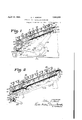
Fig. l is a side elevation ofthe forward part of a calculating machine, showing the keyboard attached thereto. f
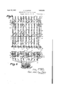
Fig. 2 is a` sectional -view of the keyboard .taken between two banks or, rows of amount keys, showing a key depressed and before the handle has been pulled.
' Fig. 3 is a horizontal section looking at the keyboard from the bottom.
Fig. 4 is a transverse section taken at right angles'to the banks of amount keys.
Fig-5 is a fragmentary side elevatlon and section of the forward part of the keyboard showing one of the banks of amount keys and associated parts after the handle has started forward.
Fig. 6 is a front end elevation of the keyboard showing only the first key in each of the assembly connections ofthe keyboard frame.
The invention is illustrated in connection with a calculating machine of the type shown in my co-pending application, Serial No. 84,616, tiled J anuary29, 1,926, of which the present application is a division. No attempt will be made to describe said machine in detail in this application as it is not essential to an understanding of the keyboard. Reference is made to said co-pending application for any features of the machine not herein described. ln order to avoid the use of reference numerals of high order and in order that the reference numeralsmay be in logical sequence, a new set of referencek numerals will be used in this application.
The keyboard frame comprises a top plate 20, and a bottom plate 2l which are spaced apart and secured to three vertical plates 22 (Fig. 4). As shown in Fig. 9 the lower edges -of the vertical plates have projections 23 extending into slots in the lower plate 2l,the corners of the projections being swaged out to bear against the lower face of the plate 21 to hold the vertical plates in position. The
vertical plates are provided with rectangular openings 24 near their upper edges, which communicate with the edges by narrow slots 25. The upper edges ofthe vertical plates are also provided with projections 26 which extend into slots in the top plate 20. The top plate` 2O is connected to the vertical plates by a means of nuts 27 mounted in the openings 24 and provided with grooves 28 across their upper faces into which the portions of the vertical plates constituting the upper edges of the openings 24 are adapted to be seated. In assembling the keyboard frame, the nuts 27 are slipped into the openings 24 and then raised so that the upper edges of the openings engage in the grooves 28 after which the sides of the openings in the vertical plates immediately below the nuts are struck out to form projections 29 which hold the nuts in place. The plate 2() is then placed on top of the vertical plates with the projections ,26 fitted into the slots in the plate 20. Screws 30 are then screwed into the nuts 27, the heads of the screws projecting laterally over the plate 2O and holding it in place as illustrated in Fig. 4. A
The vertical plates 22 are provided at their forward ends with downwardly extending projections 32 (Fig. 9) and at their rear ends with similar projections 33. The forward projections 32 serve as bearings fora cross shaft 34 which is carried bythekeyboard unit and upon which certain parts are mount- -ed as will be hereinafter explained. The
rear projections are adapted to extend down on the outside of one of the sideplates and on one side of one of the center plates of the calculating machine and are provided with openings to receive screws 35 as illustrated in Fig. l. The two right hand vertical plates 22 also have downwardlyv extending hooks 36 which are adapted to engage over headed studs 37 on the frame plate of the machine.
The keyboard may be removed as a unit by simply withdrawing the screws 35 at the rear afterwhich it -may be shifted slightly rearwardly and raised off the machine. It may, ofcourse, be mounted as a unit on the machine by reversing these operations. When seated in position the parts carried by it cooperate with the other mechanism ofthe machine as hereinafter described.
The keyboard is provided with a plurality of banks of amount keys 10 accompanied by a bank of control keys at the right hand side of the keyboard comprising an error key E, a repeat key R, a non-add key N A, a total key T and a sub-total key S T. One of the advantages of the keyboard is that the amount keys and the control keys are of similar construction; they are mounted in the keyboard in the same way, and the control keys are all located in a group in a single bank at the right hand side of the keyboard where they may be conveniently manipulated.
The stem of each amount -key comprises a flat plate 40 which slides vertically in transverse slots in the top and bottom keyboard plates 20 and 21. Each stem has two long parallel vertical slots 41 (Fig. 4) above which are two shorter vertical slots 42. The
' key stems are guided inthe keyboard frame by positioning plates 43 which extend through the right hand vertical slots 41 as jshown in Figs. 2 and 4. These plates are held firmly in position by a rod 44 (Fig. 2) which projects vthrough each plate and through the fixed plates 22 of the keyboard frame. The positioning plates 43 have projections 45 (Fig. 2) contacting the lower side of the top plate 20 of the keyboard Ito prevent the plate coming in Contact with slidable latching plates to be presently described.
The stems 46 of the control keys are similar to those of the amount keys, except that instead of having parallel vertical slots, the two parallel slots are merged into larve vertical slots 47 Y and 48 as illustrated in lFig. 8, with the exceptionof the error key which is v not latched down, in order to accommodate additional locking plates hereinafter described. The control keys are limited in their movement and prevented from binding in the frame by a plate 43 similar to the .control keys and their associated plates for the amount keys and located at the eft side of the slot 47.
It will be observed from Fig. 6 that the arts are on the outside of the right han vertical frame plate22 where they are easily accessible.-
In order to' latch the amount keys in depressed position slidable plates 50 are provided for each bank of keys which extend through the left hand vertical slots 41 in the key stems of that bank. These plates are normally .urged forward by springs 51 connected at one end to lateral projections 52 on the rear ends of the fixed plates 43 and at their otherends to upwardly extending projections 53 on the sliding plates. The plates 50 have a series of upwardly extending projections 54 (Fig. 5) provided with beveled noses 55 adapted to be positioned in the vertical slots in the key stems. In the normal undepressed position `of the keys the noses extend slightly into the upper ends of the left hand vertical vslots in the key stems as shown in Fig. 2. When a key is depressed to the position of one of the keys illustrated in Fig. 2 the portion of the key stem between the long and the short vertical slot cams the plate 50 rearwardly against the tension of its spring 51 after which it is again moved forwardly by its spring to .a position in which the nose projects into the upper vertical slot in4 the stem. This latches the key in depressed position, but does not prevent depression of a second key until the handle has started forward. Depression of a second key will release the first since the latch plate is moved to releasing position during depres` sion of the second ke The control keys are likewise latched in dcpressed position by a similar latching plate 50 illustrated in Figs. 1 and 8.
The latch plates 50 also lfunction in connection with the zero stops and safety mechanism of the machine as follows:
Each plate 50 has a hook-shaped forward end as illustrated in Fig. 1 which extends over a lateral. lug 61 on a zero stop member 62 pivoted on the shaft 34. There is one of these zero stop members for each latch plate and, with the exception of the member corresponding to the control bank of keys, each has a rearwardly extending zero stop arm 63 (Fig. 2) adapted to be positioned in front of its respective stop bar 233 tol prevent the bar from moving when no key has been depressed in the corresponding numeral key bank. Each of these zero stop membersI including that of the control bank also has a downwardly extending arm which is bifurcated to form a front portion 64 and a rear portion 64 which straddle the shaft 65 supported by the links 66 pivoted on the shaft 34 as Aillustrated are normally urged in a counter-clockwise direction tocause the forward porti ns 63 of the bifurcated ends of the zero stopgdo contact the shaft 65. The shaft 65 is urged rearwardly by a spring 67 but is normally blocked from movement as will be later explained.
When the machine is given a stroke of operation the cam 74 (Fi 1) is rocked counterclockwise from the position illustrated in Fig. 1, by the handle 70 or by a motor and is then returned to said position. This cam carries a stud 200 contacting the rear end of a plate 201 slidably guided in slots in the frame plates 202, its sliding movement being limited by the pin 2 03. The sliding plate is normally urged rearwardly by a spring 205which also tends to draw the frontend of the plate 201 upwardly but the latter movement is normally prevented by the contact of a projection 206 on therear of the plate with one of the frame plates 202. The front end of this plate 201 is provided with an upper shoulder 207 and a lower shoulder208both of which are adapted tol contacta cam roller 209 carried by the shaft 65.
tio
In the normal position of the parts illustrated in Fig. 1 the plate 201 is prevented from moving rearwardly by the roller stud 200 and from tilting upwardly by the projection 206 which engages the frame piece 202. The shaft 65 is blocked from moving rearwardly by the engagement ofthe 'roller 209 with the shoulder 207. During the vforward stroke of the machine the Astudv 200 moves away from' the plate and the latter is thereupon moved rearwardly by .the spring 205 which also rocks it cloc 203, the sliding movement being limited by the stud 203 and the rocking movement by the engagement of a projection 213 on the end of the plate with the roller 209.
The rearward movement of the plate 201 permits the shaft 65 to move rearwardly until stopped by the upper face 68 of a limiting stop 69 which contacts the under side of the keyboard plate 21. The plate 201 continues slightly rearward to provide clearance for the shoulder 208 to get behind the roller 209. This permits the zero stop members 61 to rock counter-clockwiselunder the action of springs 51 which urge the latch plates 50 forward.
In banks of amount keys where no key has been depressed the latch plates 50 are free to move forward until the forward portions 63 of their zero stop members 61 contact the shaft 65 which moves to its rear position when lthe handle is operated as just explained.
Such movement of the plates moves the noses 55 through the lower long vertical slots in the key stems a suflicient distance to lock both the amount and the control keys against movement, during operation of the machine-also in the numeral key banks, the zero stop members 61 move counter-clockwise-sutticiently to wise about the stud.
move the .zero stop arms 63 in front of their .differential stop bars 233 to prevent the bars land their associated actuator segments from moving, it being understood that the stop arm 63 is omitted fromx the control bank.
In banks of amount keys where a key has been de ressed, the latch plates 50 can move forwar slightly, but only a limited distance since the projectlons 54 on the plates contact the portion of the key stems between the upper and lower slots as will be clear from Fig. 2. The forward movement isl suiiicient to lock the keys in position but it is not suicient to permit the zero stop arms 63 to b e moved in front of their differential stop bars.` Accordingly the stop bars for the banks of keys in which amount keys have been depressed are free to move.
VVhenone of the amount keys is depressed, the rearward movement of its latching plate 50 moves its zero stop clockwise and when-the l'atching plate again moves forward to latch the key in depressed position the zero stop movesback to normal position. If one of the keys should Abe stopped in partially depressed position, the latch plate cannot be.
moved forward because the nose 55 contacts the portion of the key stem between the top and bottom vertical slots. This prevents the zero stop from moving counter-clockwise and prevents the shaft 65 from moving rearwardly when the machine is operated, The blocking of the shaft 65 causes the operating mechanism to be automatically disconnected from the driving shaft through the medium of arm 193 (Fig. 2) as explained in my (fo-pending application. The latch plates 50 thus control the automatic disconnecting feature; they control the zero stops and they serve both as a latching and a locking means for the keys.
During the return stroke of the machine the stud 200 on the cam 74 contacts the end of the plate 201 and moves it forward thereby causing it to move the shaft 65 forward, rock the members 61 clockwise, and move the latching plates 50 rearward to release all the depressed keys. The shoulder 208 being farther forward than shoulder 207 causes the shaft 65 and associated parts to be moved beyond their normal forward position so as to insure that the keys will be released. As the slide 201 reaches the end of its forward position the projection 206 contacts the frame member 202 and the slide is rocked counter-clock wise about stud 203 thereby causing the shoulder 208 to move down past the roller 209. which then moves rearwardly into contact with shoulder 207 and allows the parts to assume their normal position.
When the keys are released they are returned to normal position by a simple, inexpensive, and easily accessible means illustrated in Figs. 1, 2 and 5. The lower ends of the key stems on the under side of the key- -tended as illustrated in Figs. 2 and 5.
lVhen a key in a particular bank is depressed the spring 71 for that bank is ex- The extension of this spring is sufiicient to cause it to urge the depressed key upwardly and, when the key is released, the spring immediately moves it to its normal undepressed posit-ion. If, while one of the keys is depressed, another key in the same bank is depressed, the extension of the spring by the second key will place a slightly increased force on the first key tending to move it to its undepressed condition and since the depression of the second key moves the latch plate to unlatched position the first key will be moved to undepressed condition when the second key is depressed, thereby providing what is called a flexible keyboard.
This construction for returning the keys is simple, easily'accessible, and the number of parts is a minimum. It is not necessary to provide springs for each key as is frequently done. All the parts are on the bottom of the keyboard where they are easily accessible and it is a simple matter to remove any of the springs by simply removing one of the end rods which holds it in position. The use of eyes pressed out from the bottom plate also reduces the number of parts.
The lower ends of the key stems of the amount keys are adapted to contact differential stops 252 onthe stop bars 233 as illus'- trated in Fig. 4. Since some of these stops are offset the keys are provided with cut away portions 7 5 so as to leave remaining portions'which may be positioned to engage their respective stops and at the same time leave space to permit other stops to pass them.
Suitable interlocking mechanism is provided between the control keys to prevent depression of more vthan one control key at a time. This comprises a series ofplates 8O A small rod 72' (Fig. 1) prorear plate 80. The plates 8O have beveled i portions for the key stems to strike and the limit of movementI of the plates between the limiting studs is equal to the width'of one key stem. When one of the control keys other than the error key is depressed, the part of the key stem above the slot 47 passes between the two adjacent plates 8O or in front of the foremost plate -or back of the rearmost plate asthe case may be, thus moving the plates together and preventing depression of another control key other than the error key 'as will be clearly understood-from Fig. 7. It will be observed that the latch plate 50 (Fig. 1) will be'actuated during depression of a key before the interlock operates. This means that if the control key is depressed, another may be depressed without operating the error key as is usually required. Depression of the control key releases the key already depressed but two control keys cannot be depressed at the same time.y This gives a flexible bank of control keys and at the same time provides an interlock that prevents two 'control keys being depressed simultaneously.
The forward plate 81 also has a lateral lug 85 that prevents a subtraction lever (not shown) operating in slot 86 from moving to its proper position at the rear of the slot when one of the control keys is depressed.
The error key is employed to release any depressed amount or control key when the Wrong key has been depressed. The locking plate 50 for the control keys has pivoted to it an arm 84. the upper forward end of which projects into aI notch formed in the error key stem. lVhen the error key is depressed it moves the locking plate 50 for the control keys rearwardly considerably further than when the plate is moved rearwardly on depression of one of the other control keys with the result that the corresponding mem- 'ber 61 is rocked clockwise suiiiciently to force the shaft forwardly and thereby move all of the other latch plates 50 rearmav have been depressed.
Interlocking means is provided between the total and sub-total keys and the amount keys to prevent depression of the latter when a total or sub-total is being` taken. For this purpose there is provided a cross slide 90 mounted in slots formed in the vertical keyboard plates 22. A spring 91 (Fig. 3) is mounted in a recess in the forward end of the slide and compressed between one end of the recess and the left hand plate 22. This spring 'wardlv far enough to release any keys that normally urges the slide to the position illustrated in Fig. 3 so that slots 92 in the rear edge of theslide are normally opposite the noses 55 on the'projections 54 of the locking plates 50. fThe plates 50 are thus fre to 5 move without interference from' the'cross slide when amounts are being enteredin the. machine with the total or sub-total keys in normal position. The right hand end of the slide 90 has an integral depending portion 1 93-which rests on the lower plate V21 of the keyboard and which has inwardly extending ears-94 and 95 projecting into recesses in the Sides of the total and sub-total key stems respectively. The upper ends of the recesses are inclined at 96 as illustrated in Fig. 4 so that when the total or sub-total key is depressed the slide 90 is moved to the right and the notches 92 are moved from in front of the noses on the latching plates 50 so that when 2- these plates move forward the noses strike the' edge of the cross plate 90 instead of entering the notches. l y Accordingly, when either the total or subtotal key` is depressed and the machine is operated the plates 50 move forward until their noses engage the edge of the slide 90 which movement is sulicient to position the Aplates to lock the keys against movement, but is not suliicient to permit the zero stops 0 61 to move the zero stop arms 63 in front of the stop bars. Since the crossbar 90 acts on all the latch plates 50 none of the zero stop arms can move to arresting position and f hence all the stop bars are free to move, a
condition which is necessary in the taking of a total. The movement of the latching plates/50 is suiiicient to move the members 61 so that they do not block the control rod 65 enough to cause the machine to be automatically disconnected.
It will thus be seen that there has been pro- -vided a simple, .unitary keyboard construcf tion that may be readily attachedsto and detached from a calculating machine. In addition to carrying the keys and associated locking parts and mechanisms, the keyboard carries the zero stops for the differential mechanism. The latch plates for latching 0 the keys in depressed position also actas locking plates and theyy further act to move the zero stops to control the dilerential mechanism as well as to control the safety disconnecting feature. When the keyboard f is placed in position the zero stops are positioned relative to the stop bars and the slide 201 so as to be inoperative relation to them and thekkeys are in position for their stems to act as stops for the diilerential stop bars.
It is to be understood that the structure shown is for purposes of illustration only and that variations may be made in it without departing from the spirit and scope of the invention as defined by the appended claims.
I claim:
1. Acalculatin machine keyboard having a pluralit of ba s of keys, a latching plate for each ank a cross shaft, a plurality of zerostop members pivoted to the cross shaft, and a control rod pivoted to swing about the cross shaft, one end of each zero stop being connected to its respect-ive latching plate to 3. A calculating machine keyboard section having a plurality of'banks of depressible.
keys, a latching plate for each bank, a pivoted zero stop member connected to each latchingplate,each of said zero stop members having a bifurcated end, and a control rod carried by the keyboard and positioned in the slots in the ends of the zero stop members, the diameter of said control rod being less than the width of said slots.
4. A calculating machine keyboard having a plurality of banks of depressible amount keys, a latch plate for each bank, a zero stop member controlled by each latch plate, a
control rod carried by the keyboard for con-` trolling the operation of the zero stop members and latch plates, an error key having a latch plate and a member associated 'with the control rod similar to said zero stop# members, connections between the error key and its latch plate vfor causing depression of the error key to move its latch plate to actuate the control rod to release the latches for the banks of amount keys.
5. Acalculating machine keyboard having spaced top and bottom plates, banks of depressible keys having stems extending through both plates and slidably mounted therein, each of said stems being provided With two spaced parallel slots, stationary l guide plates for each bank of keys positioned between the top and bottom plates, each guide plate extending through one set of slots vin the keystems of its bank to guide A the keysV and being provided with portions which hold the top and bottom plates in spaced relation, and slidable key latching plates extending through the other set of slots in the stems of each key bank.
6.A A calculating machine keyboard having spaced top and bottom plates, banks of-depressible keys having stems extending through both plates and slidably mounted 4plates being provided with portions for holding the top and bottom lates in spaced relation, and key latching p ates positioned between the top and bottom plates, each of said latching platesbeing slidably mounted in the other set of slots in the key stems of its bank.
7 L A calculating machine keyboard having banks 4of depressible keys, a latching plate for each bank movable yforward and backward, a zero stop member for each latching plate, and a common control rod for said zero stops, each zero stop member being connected to its latch plate to move in both directions with said plate to enable the control rod to control the latches in both directions of their movement.l v
8. A calculating` machine keyboard having banks of depressible keys, latch plates for latching said keys in depressed position, zero stop members connected to said latch plates to move with them, an error key, and mechanism operatively connecting the error key with the zero stop members whereby depression of said error key willy move said zero stop members to move said latch plates to release depressed keys.
9. A calculatingr machine keyboard having banks of depressible keys, latch plates for latching said keys in depressed position, zero stop members connected to said latch plates to move with them, a control rod for controlling saidzero stop members, an error key, and connections between said error key and said control rod for moving the control rod when the error key is depressed to thereby r' move the zero stop members to move the latch plates to release vdepressed keys.
10. A calculating machine keyboard having a plurality of banks of depressible amount keys, each bank having a latch plate for latching its keys in depressed position` a zero stop member for each 'latch plate` said zero stop being normally out of arresting position, means for moving each latch plate to move its Zero stop to arresting position when no key in its bank is depressed, a total key,
nand means controlled by said total key when it is manipulated for limiting the movement of the latch plates ot all the banks to thereby prevent the zero stops in all banks from moving to arresting position.
' 11. A calculating machine keyboard having a yplurality ot banks of depressible amountlkeys, a latching and locking plate for each bank for latching and for locking its keys in position, a zero stop member for each latch plate, each latch plate being movable to one position to latch a depressed key of its bank in depressed position and to another position to lock all the keys of its bank, said plate acting when no key in its bank is'depressed to move its zero stop to arresting position, a total key, and means set by depression of said total key vfor limiting the movement of the latch plates in all the banks to prevent their zero stop's from moving to arresting position while still allowingthe latch plates to move to key-locking position.
12. A keyboard for calculating machines having banks of depressible amount keys# a latch plate for each bank for latching the chines comprising a structure, supporting.
rows of depressible keys, a plurality of latching plates for latching the keys in depssed position, a shaft mounted on one end of said "structure, a plurality of zero stops pivoted on said shaft, said zero stops being connected to said latch plates to act to release said 1plates, and a rod pivotally supported by said eyboard and positioned to cooperate with said zero stops to be controlled bythem and to act on them to release the latch plates.
14'. A keyboard for calculating machines having rows of depressible keys, a latch plate for each row, a pivoted zero sto member connected to each latch late, sa-i zero stop members having relative y wide slots therein, and a control rod positioned in said slots, the diameter of said rod being less than the width of said slots. p
15. A calculating machine keyboard having a plurality of banks of depressible amount keys, a zerostop member for each bank of keys, said zero stop members being normally out of larresting position, means for nov moving all of said zero stops to arresting position, and means operated by depression of each amount key for altering the movement of the zero stop of its bank toward arresting position by said moving means tothereby prevent said zero stop from reaching arresting position.
16. In a calculating machine having an operating mechanism, banks of depressible amount keys, a latch plate for each bank of amount keys to latch the keys in depressed position, and depressible control keys; a zero stop controlled by each plate and normally inv non-arresting position, means for movin the latch plates as the machine isv operate to move the zero stops to arresting position, and means set by depression of one ofgsaid control keys acting to arrest the latch plates as the machine is operated to thereby prevent the zero stops from reaching arresting position when the machine is operated with a control key depressed.
17. The combination in a calculating machine of a series of stop members released by' operation of the machine for movement against stops positioned by amount keys, a zero stop for each stop member normally positioned solas to permit movement of said member, and meansactuated by operation of the machine acting to move all the zero stops for members for which no key stops have been set to. positions to prevent movement of their respective stop members.
18. In combination, in la calculating ma- 2'0 chinehaving banks Vof depressible keys -and stop members released by operation of the machine for movement against stops set by depression of said keys; a latching and locking plate for the keys of each bank, means 25 urging said plates toward locking positions beyond their latching positions, a zero stop member connected to each plate. means for limiting the movement of said plates to retain them in latching position-with the zero stops out of position for arresting.l the stop bars, said last-named means acting automatically upon operation of the machine to re-l lease said latch plates for movement to locking position, said latch plates and keys having. cooperating portions which permit the latch plates in blanks in which no keys have been depressed to move to locking position such that their zero stops move to arresting position and which permit the latch plates in banks in which a kev has been depressed to i by said operating mechanism, and av pivoted zero stop member connected to each latching device, all of said Zero stop members being associated with said control rod to control movements thereof and to be controlled by it.
In testimony whereof I have subscribed my name. y
ALLEN A. HoRToN.
move to locking position but which limit the movement of said plates in the latter banks to prevent the zero stops from reaching arrest. ing position.
19. A calculating machine keyboard having a plurality of banks of depressible kevs provided with key stems1 a latching` and locking` plate for each bank extending through slots in the kev stems of its bank and adapted to occupy both a latching and a locking position relative to said l key stems. means urging said plates toward their latching and locking positions, each plate having proiections engageable bv the key stems of its bank so that, when a key in its bank is depressed. the plate for said bankl is moved after which it automatically returns to normal position to latch the key depressed, control means normally holding said plates in latching condition, and means moving said control means as the machine is operated to free said plates to enable them to move to locking position whereby the plates act to lock the keys in position.
l CL' 20. In a calculating machine having an
Priority Applications (1)
| Application Number | Priority Date | Filing Date | Title |
|---|---|---|---|
| US127511A US1853051A (en) | 1926-01-29 | 1926-08-06 | Keyboard for calculating machines |
Applications Claiming Priority (2)
| Application Number | Priority Date | Filing Date | Title |
|---|---|---|---|
| US84616A US1853050A (en) | 1926-01-29 | 1926-01-29 | Calculating machine |
| US127511A US1853051A (en) | 1926-01-29 | 1926-08-06 | Keyboard for calculating machines |
Publications (1)
| Publication Number | Publication Date |
|---|---|
| US1853051A true US1853051A (en) | 1932-04-12 |
Family
ID=26771195
Family Applications (1)
| Application Number | Title | Priority Date | Filing Date |
|---|---|---|---|
| US127511A Expired - Lifetime US1853051A (en) | 1926-01-29 | 1926-08-06 | Keyboard for calculating machines |
Country Status (1)
| Country | Link |
|---|---|
| US (1) | US1853051A (en) |
Cited By (6)
| Publication number | Priority date | Publication date | Assignee | Title |
|---|---|---|---|---|
| US2583810A (en) * | 1952-01-29 | Accumulator state control | ||
| US2616623A (en) * | 1952-11-04 | Accounting machine | ||
| US2678162A (en) * | 1954-05-11 | Computing machine | ||
| US2991008A (en) * | 1961-07-04 | goldberg | ||
| US3169173A (en) * | 1962-02-01 | 1965-02-09 | Gen Electric | Push-button switch operable by external actuator |
| US20120048700A1 (en) * | 2010-09-01 | 2012-03-01 | Sunrex Technology Corp. | Computer keys with inwardly tapered bottom |
-
1926
- 1926-08-06 US US127511A patent/US1853051A/en not_active Expired - Lifetime
Cited By (6)
| Publication number | Priority date | Publication date | Assignee | Title |
|---|---|---|---|---|
| US2583810A (en) * | 1952-01-29 | Accumulator state control | ||
| US2616623A (en) * | 1952-11-04 | Accounting machine | ||
| US2678162A (en) * | 1954-05-11 | Computing machine | ||
| US2991008A (en) * | 1961-07-04 | goldberg | ||
| US3169173A (en) * | 1962-02-01 | 1965-02-09 | Gen Electric | Push-button switch operable by external actuator |
| US20120048700A1 (en) * | 2010-09-01 | 2012-03-01 | Sunrex Technology Corp. | Computer keys with inwardly tapered bottom |
Similar Documents
| Publication | Publication Date | Title |
|---|---|---|
| US1853051A (en) | Keyboard for calculating machines | |
| US2424359A (en) | Adding machine | |
| US2741426A (en) | golemon | |
| US1730147A (en) | horton | |
| US2091778A (en) | Keyboard construction and key control | |
| US1909715A (en) | pasinski | |
| US3045799A (en) | Keyboard interlock control means | |
| US2422103A (en) | Duplex calculating machine | |
| US2298202A (en) | Listing calculator | |
| US2650027A (en) | Keyboard interlock | |
| US1914401A (en) | Calculating machine | |
| US1874700A (en) | Calculating machine | |
| GB643868A (en) | Typewriting machine | |
| US2801047A (en) | landsiedel | |
| US1913510A (en) | Calculating machine | |
| US3084855A (en) | Ten-key adding machine fo r non-uniform | |
| US2033045A (en) | Computing machine | |
| US1141348A (en) | Adding-machine. | |
| US1949445A (en) | Adding machine | |
| US2285311A (en) | Accounting machine | |
| US3013717A (en) | Electromechanical controls for calculating machines | |
| US2740582A (en) | parker | |
| US1646105A (en) | peters | |
| US3018044A (en) | anderson | |
| US2684808A (en) | Automatic spacing stroke control mechanism for accounting machines |