US1853047A - Floor polishing attachment for suction cleaners - Google Patents
Floor polishing attachment for suction cleaners Download PDFInfo
- Publication number
- US1853047A US1853047A US320304A US32030428A US1853047A US 1853047 A US1853047 A US 1853047A US 320304 A US320304 A US 320304A US 32030428 A US32030428 A US 32030428A US 1853047 A US1853047 A US 1853047A
- Authority
- US
- United States
- Prior art keywords
- attachment
- floor
- suction
- cleaner
- casing
- Prior art date
- Legal status (The legal status is an assumption and is not a legal conclusion. Google has not performed a legal analysis and makes no representation as to the accuracy of the status listed.)
- Expired - Lifetime
Links
Images
Classifications
-
- A—HUMAN NECESSITIES
- A47—FURNITURE; DOMESTIC ARTICLES OR APPLIANCES; COFFEE MILLS; SPICE MILLS; SUCTION CLEANERS IN GENERAL
- A47L—DOMESTIC WASHING OR CLEANING; SUCTION CLEANERS IN GENERAL
- A47L11/00—Machines for cleaning floors, carpets, furniture, walls, or wall coverings
- A47L11/40—Parts or details of machines not provided for in groups A47L11/02 - A47L11/38, or not restricted to one of these groups, e.g. handles, arrangements of switches, skirts, buffers, levers
- A47L11/4036—Parts or details of the surface treating tools
- A47L11/4041—Roll shaped surface treating tools
-
- A—HUMAN NECESSITIES
- A47—FURNITURE; DOMESTIC ARTICLES OR APPLIANCES; COFFEE MILLS; SPICE MILLS; SUCTION CLEANERS IN GENERAL
- A47L—DOMESTIC WASHING OR CLEANING; SUCTION CLEANERS IN GENERAL
- A47L11/00—Machines for cleaning floors, carpets, furniture, walls, or wall coverings
- A47L11/02—Floor surfacing or polishing machines
- A47L11/20—Floor surfacing or polishing machines combined with vacuum cleaning devices
- A47L11/204—Floor surfacing or polishing machines combined with vacuum cleaning devices having combined drive for brushes and for vacuum cleaning
-
- A—HUMAN NECESSITIES
- A47—FURNITURE; DOMESTIC ARTICLES OR APPLIANCES; COFFEE MILLS; SPICE MILLS; SUCTION CLEANERS IN GENERAL
- A47L—DOMESTIC WASHING OR CLEANING; SUCTION CLEANERS IN GENERAL
- A47L11/00—Machines for cleaning floors, carpets, furniture, walls, or wall coverings
- A47L11/40—Parts or details of machines not provided for in groups A47L11/02 - A47L11/38, or not restricted to one of these groups, e.g. handles, arrangements of switches, skirts, buffers, levers
- A47L11/408—Means for supplying cleaning or surface treating agents
- A47L11/4088—Supply pumps; Spraying devices; Supply conduits
-
- A—HUMAN NECESSITIES
- A47—FURNITURE; DOMESTIC ARTICLES OR APPLIANCES; COFFEE MILLS; SPICE MILLS; SUCTION CLEANERS IN GENERAL
- A47L—DOMESTIC WASHING OR CLEANING; SUCTION CLEANERS IN GENERAL
- A47L11/00—Machines for cleaning floors, carpets, furniture, walls, or wall coverings
- A47L11/40—Parts or details of machines not provided for in groups A47L11/02 - A47L11/38, or not restricted to one of these groups, e.g. handles, arrangements of switches, skirts, buffers, levers
- A47L11/4094—Accessories to be used in combination with conventional vacuum-cleaning devices
Definitions
- This invention relates to floor polishing attachments for suction cleaners and has for its principal-object the provision of simple and efiectrve means for conve'rtinga suction 5 cleaner into an eflicient floor pohsher.
- a further object of my invention is to provide a novel attachment thru the use of.
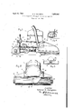
- Fig. 1 is a side elevation of a common type of suction cleaner with my invention applied thereto.
- FIG. 2 is a front elevation of the floor polishing attachment applied to suction cleaner andhavinga section of the hood-broken away showing the brush therein.
- Fig. 3 is a rear View of the attachment on a reduced scale. 7
- Fig. 4 is a partial cross section upon a vertical plane through the attachment pul 1 y. p
- reference numeral 1 indicates generally a suction cleaner of a common type including amotor' and fan with the rear supporting castors of said cleaner in their uppermost position and with the dust bag removed.
- the pulley 9 at the end of the shaft 10 is disconnected from the agitating means (not shown) within the hood.-
- the discharge conv duit 11 leading from the fan chamber 19 has at its'end the transverse attaching plate 5 supplied with the securing means 6.
- the reference numeral 2 indicates my attachment device in general.
- the body or casing comprises a hood 3 which houses and supports the floor polishing brush 14 and which is provided on its rear face with the upright attaching plate 4 provided with outstanding ears 21 forming slots 22 therewith and adapted to co-operate with the plate 5and securing means 6 in maintaining'th'e attachment and cleaner proper in operative relation.
- Fig. 2 ofthe drawing the rotary brush His positionedin the hood 3 by means of journals 20 secured therein;
- the brush is of theusual floor polishing type being made of extremelylstrongand durable bristles well secured, said brush supporting the wei ht of the polisher-end' of the machine w en in operation.
- 'At the'center of the brush is provided a pulley 17 adapted to .plate 4 and, when the attachment is in operative position; as shown in Figs. 1 and 2,
- the cleaner motor drives the fan 21 within the fan chamber 19, as in the normal operation of the machine as a suction cleaner, drawing air in thru the fan chamber 19 and forces it into the exhaust outlet 11 and thence thru the opening 18 and hood 3 into contact with the surface being polished where it carries away any moisture present. It has been the experience of those using a floor polisher that satisfactory results are obtained only when the floor surface is dry and my invention provides a structure ,wherein means are provided to can away any excess moisture present.
- opening 18 performs a second and valuable function in that it permits of the circulation of a suflicient quantity of air thru the cleaner to insure a coolmotor, yet at the same time throttles the air flow through the fan chamber excessively to prevent the fan from placing a useless load on the motor.
- a floor-polis ing attachment including means for lishing the floor surface, means ,for securing said polishing means to the 'exhaustoutlet of the casing, and means to direct a flow of dr ing air from said'casing toward the floor sur ace.
- the combination of the main casing including a fan chamber and exhaust outlet, and the suction-creating means including a fan within the fan-chamber of a suction cleaner with a floor-polishing attachment including a casing, floor polishing means in said attachment casing, and means to attach said casing to the exhaust outlet of said cleaner casing, characterized by the fact that said attachment casing is provided with a downwardly facing opening and .is interiorly connected to said exhaust outlet.
- a floor polishing attachment for sizetion cleaners a casing, a rotatable brush mounted in said casing, and projecting below the lower edges thereof and serving as a support therefor, a plate attached to said casing, and means on said plate for removably securing said attachment on a suction cleaner, said means comprising outstanding ears on said plate formin screw-receiving slots and a channeLmem r at the lower end thereof.
Description
A ril 12, 932. v
E. A. HAMPSON LOOR POLISHING ATTACHMENT FOR SUCTION CLEANERS- Filed Nov. 19, 1928 an. :unlllln llll IIIIIIIII E- lnven+or Ed W0 rd A. Horn sbn ornez/ Patented Apr. 12, 1932 UNITED STATES EDWARD A. merson, or GHIGAGQ'ILLLNOIS, assrouon' 'ro ran noovna comm. A
PATE T "OFFICE CORPORATION OF ILLINOIS FLOOR romsnme airracnimnr FOB SUCTION cnmnnns Applicationfllcd November 19, 1928. 2 Serial No. 320,304.
This invention relates to floor polishing attachments for suction cleaners and has for its principal-object the provision of simple and efiectrve means for conve'rtinga suction 5 cleaner into an eflicient floor pohsher.
- A further object of my invention is to provide a novel attachment thru the use of.
floor polishing attachment for suction cleaners as hereinafter fully described with reference to the accompanying drawing wherein is illustrated a preferred embodiment of my invention, like. numerals representing like parts thruout. Y In the drawing:
' Fig. 1 is a side elevation of a common type of suction cleaner with my invention applied thereto.
'Fig. 2 is a front elevation of the floor polishing attachment applied to suction cleaner andhavinga section of the hood-broken away showing the brush therein. I
Fig. 3 is a rear View of the attachment on a reduced scale. 7
Fig. 4 is a partial cross section upon a vertical plane through the attachment pul 1 y. p
In the drawings reference numeral 1 indicates generally a suction cleaner of a common type including amotor' and fan with the rear supporting castors of said cleaner in their uppermost position and with the dust bag removed. The suction ho'od 13, compris ing the front of'the cleaner, when so used 10 but the rear when. the'machine is used as a floor polisher, issupported, by wheels 12.
The pulley 9 at the end of the shaft 10 is disconnected from the agitating means (not shown) within the hood.- The discharge conv duit 11 leading from the fan chamber 19 has at its'end the transverse attaching plate 5 supplied with the securing means 6.
The foregoing comprises in itself no part of my present invention except'i'nsofar asthe application of my attachment thereto is an invention, -being merely an arrangement of a common cleaner which is described so that a better understanding of my applied invention may be had Referring againto the drawing. the reference numeral 2 indicates my attachment device in general. The body or casing comprises a hood 3 which houses and supports the floor polishing brush 14 and which is provided on its rear face with the upright attaching plate 4 provided with outstanding ears 21 forming slots 22 therewith and adapted to co-operate with the plate 5and securing means 6 in maintaining'th'e attachment and cleaner proper in operative relation. This late 4 completely closes the outlet opening 0 the suction cleaner with the exception I of the aperture-18, hereinafter described, so as to reduce the amount of air'handled by. the fan and consequently the load on the motor. At its lower edge the plate 4 is provided with an.upturned lip 8 forming with the plate 4 a channel or groove 15. which receives a lower edge 16 of the plate 5 of the discharge outlet 11. The lip 8 is so positioned that when the edge 16 is properly seated in the channel 15 and the machine placed on the floor in operative position,'the suction nozzle end of the machine will be removed from the floor surface a suflicient distance to prevent contact therewith.
Referring to Fig. 2 ofthe drawing the rotary brush His positionedin the hood 3 by means of journals 20 secured therein; The brush is of theusual floor polishing type being made of extremelylstrongand durable bristles well secured, said brush supporting the wei ht of the polisher-end' of the machine w en in operation. 'At the'center of the brush is provided a pulley 17 adapted to .plate 4 and, when the attachment is in operative position; as shown in Figs. 1 and 2,
opens into the discharge conduit 11. With the polisherin operation the cleaner motor drives the fan 21 within the fan chamber 19, as in the normal operation of the machine as a suction cleaner, drawing air in thru the fan chamber 19 and forces it into the exhaust outlet 11 and thence thru the opening 18 and hood 3 into contact with the surface being polished where it carries away any moisture present. It has been the experience of those using a floor polisher that satisfactory results are obtained only when the floor surface is dry and my invention provides a structure ,wherein means are provided to can away any excess moisture present.
opening 18 performs a second and valuable function in that it permits of the circulation of a suflicient quantity of air thru the cleaner to insure a coolmotor, yet at the same time throttles the air flow through the fan chamber suficiently to prevent the fan from placing a useless load on the motor.
As is clear from the foregoing description the transformation of the suction cleaner into an improved floor polisher by the use of my invention is a simple task. The operation requiringlmerely the loosening of two thumbscrews t ereby releasing the dust bag the raising of the rear supporting castor; the
.positioning of the plate 4 agalnst the plate 5 with the lower end 16 secured in the channel and the tightening of two thumbscrews;
the removal of the belt from its connection in the suction nozzle and placing same in operative relation between the pulleys 9 and 17. The resulting structure is one of unusual simplicity and stren h and produces a p01- is'her of great effectiveness.
r I claim:
1. In combination with the main casing and suction-creatin means of a suction cleaner a floor-polis ing attachment including means for lishing the floor surface, means ,for securing said polishing means to the 'exhaustoutlet of the casing, and means to direct a flow of dr ing air from said'casing toward the floor sur ace.
2. The combination of the main casing including a fan chamber and exhaust outlet, and the suction-creating means including a fan within the fan-chamber of a suction cleaner with a floor-polishing attachment including a casing, floor polishing means in said attachment casing, and means to attach said casing to the exhaust outlet of said cleaner casing, characterized by the fact that said attachment casing is provided with a downwardly facing opening and .is interiorly connected to said exhaust outlet.
3. In a floor polishing attachment for sizetion cleaners a casing, a rotatable brush mounted in said casing, and projecting below the lower edges thereof and serving as a support therefor, a plate attached to said casing, and means on said plate for removably securing said attachment on a suction cleaner, said means comprising outstanding ears on said plate formin screw-receiving slots and a channeLmem r at the lower end thereof.
Signed at Chicago, in the county of Cookand State of Illinois, this 16th day of Novemher, A. D. 1928. 1
EDWARD A. HAMPSON.
Priority Applications (1)
| Application Number | Priority Date | Filing Date | Title |
|---|---|---|---|
| US320304A US1853047A (en) | 1928-11-19 | 1928-11-19 | Floor polishing attachment for suction cleaners |
Applications Claiming Priority (1)
| Application Number | Priority Date | Filing Date | Title |
|---|---|---|---|
| US320304A US1853047A (en) | 1928-11-19 | 1928-11-19 | Floor polishing attachment for suction cleaners |
Publications (1)
| Publication Number | Publication Date |
|---|---|
| US1853047A true US1853047A (en) | 1932-04-12 |
Family
ID=23245799
Family Applications (1)
| Application Number | Title | Priority Date | Filing Date |
|---|---|---|---|
| US320304A Expired - Lifetime US1853047A (en) | 1928-11-19 | 1928-11-19 | Floor polishing attachment for suction cleaners |
Country Status (1)
| Country | Link |
|---|---|
| US (1) | US1853047A (en) |
Cited By (4)
| Publication number | Priority date | Publication date | Assignee | Title |
|---|---|---|---|---|
| US2658226A (en) * | 1949-06-03 | 1953-11-10 | Hoover Co | Floor polishing attachment for suction cleaners |
| US2663045A (en) * | 1950-03-04 | 1953-12-22 | Joseph D Conway | Portable brushing and nap-raising attachment for carpet cleaning machines |
| US3147510A (en) * | 1962-09-20 | 1964-09-08 | Thompson Miles Courtney | Industrial suction cleaner with hand suction attachment |
| DE4212733A1 (en) * | 1992-04-16 | 1993-10-21 | Hans Tuchlinski | Suction cleaner with roller brush esp. for staircase or ramp - has forward-mounted brush for simultaneous sweeping of tread on which machine rests on riser of next step |
-
1928
- 1928-11-19 US US320304A patent/US1853047A/en not_active Expired - Lifetime
Cited By (4)
| Publication number | Priority date | Publication date | Assignee | Title |
|---|---|---|---|---|
| US2658226A (en) * | 1949-06-03 | 1953-11-10 | Hoover Co | Floor polishing attachment for suction cleaners |
| US2663045A (en) * | 1950-03-04 | 1953-12-22 | Joseph D Conway | Portable brushing and nap-raising attachment for carpet cleaning machines |
| US3147510A (en) * | 1962-09-20 | 1964-09-08 | Thompson Miles Courtney | Industrial suction cleaner with hand suction attachment |
| DE4212733A1 (en) * | 1992-04-16 | 1993-10-21 | Hans Tuchlinski | Suction cleaner with roller brush esp. for staircase or ramp - has forward-mounted brush for simultaneous sweeping of tread on which machine rests on riser of next step |
Similar Documents
| Publication | Publication Date | Title |
|---|---|---|
| US3906585A (en) | Floor treating apparatus | |
| US4731956A (en) | Floor polishing machine | |
| US2192397A (en) | Suction cleaner | |
| US2250177A (en) | Floor washing machine | |
| US2237830A (en) | Floor cleaner | |
| US1853047A (en) | Floor polishing attachment for suction cleaners | |
| US3246359A (en) | Compact vacuum cleaner with storage means | |
| US1763365A (en) | Surfacing machine | |
| US2926370A (en) | Cleaning appliance for use in polishing, scrubbing or waxing floors and like structures | |
| US2517670A (en) | Converter attachment for suction cleaners | |
| US2017893A (en) | Suction cleaner | |
| US3046586A (en) | Rug scrubbing device | |
| US1697918A (en) | Floor-polishing attachment for vacuum cleaners | |
| US1657111A (en) | Attachment for vacuum cleaners | |
| US3120021A (en) | Vacuum cleaner nozzle | |
| US2197641A (en) | Vacuum cleaner | |
| US2008476A (en) | Suction cleaner | |
| US1795533A (en) | Vacuum-cleaning-machine attachment | |
| US1286115A (en) | Suction-cleaner. | |
| US1713184A (en) | Floor-polishing attachment for vacuum cleaners | |
| US3512208A (en) | Adjustment means for tool brush in vacuum cleaner | |
| US1809302A (en) | Floor polishing device | |
| US3531819A (en) | Combined floor-polisher and suction cleaner | |
| US2359223A (en) | Suction cleaner | |
| US1759731A (en) | Floor polisher |