US1853035A - Scraper for subgrading machines - Google Patents
Scraper for subgrading machines Download PDFInfo
- Publication number
- US1853035A US1853035A US539607A US53960731A US1853035A US 1853035 A US1853035 A US 1853035A US 539607 A US539607 A US 539607A US 53960731 A US53960731 A US 53960731A US 1853035 A US1853035 A US 1853035A
- Authority
- US
- United States
- Prior art keywords
- scraper
- scoop
- axle
- truck
- machines
- Prior art date
- Legal status (The legal status is an assumption and is not a legal conclusion. Google has not performed a legal analysis and makes no representation as to the accuracy of the status listed.)
- Expired - Lifetime
Links
- 230000000694 effects Effects 0.000 description 5
- 230000033001 locomotion Effects 0.000 description 4
- 241000699666 Mus <mouse, genus> Species 0.000 description 1
- 238000010276 construction Methods 0.000 description 1
- 230000002262 irrigation Effects 0.000 description 1
- 238000003973 irrigation Methods 0.000 description 1
- 230000035515 penetration Effects 0.000 description 1
- 230000001105 regulatory effect Effects 0.000 description 1
Images
Classifications
-
- E—FIXED CONSTRUCTIONS
- E02—HYDRAULIC ENGINEERING; FOUNDATIONS; SOIL SHIFTING
- E02F—DREDGING; SOIL-SHIFTING
- E02F3/00—Dredgers; Soil-shifting machines
- E02F3/04—Dredgers; Soil-shifting machines mechanically-driven
- E02F3/28—Dredgers; Soil-shifting machines mechanically-driven with digging tools mounted on a dipper- or bucket-arm, i.e. there is either one arm or a pair of arms, e.g. dippers, buckets
- E02F3/34—Dredgers; Soil-shifting machines mechanically-driven with digging tools mounted on a dipper- or bucket-arm, i.e. there is either one arm or a pair of arms, e.g. dippers, buckets with bucket-arms, i.e. a pair of arms, e.g. manufacturing processes, form, geometry, material of bucket-arms directly pivoted on the frames of tractors or self-propelled machines
- E02F3/352—Buckets movable along a fixed guide
Definitions
- This invention relates to the 'gradin'g ma-- chine which forms thesubj e'ct-matter of my copending application filed May 3, 1930, and
- the grading machine comprises a truck adapted'for movement in the path located at the side of and parallel to the axis of the canal or the like to be sub-graded, rails at right angles to the axis of the canal'or the like and extending across thetruck and there from into the canal or the like, a wheeled scraper mounted on the rails, means carried by the truck for moving the scraper along the rails in the direction of the truck, and
- the present invention which constitutes a division of my earlier application, relates to the scraper, and has for one of its objects to provide a device of this character which shall embody a wheeled truck, and a scoop mounted on the truck for adjustment to permit its cutting depth to be regulated and controlled.
- the invention has for a further object to provide a scraper of the character stated which shall embody means through the medi-' um of which the scoop may be easily and quickly adjusted to regulate its cutting depth and through the medium of which the scoop may be firmly secured in adjusted position.
- the invention consists in the construction, combination and arrangement of parts hereinafter fully described and claimed, and illustrated in the accompanying drawings,
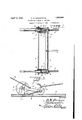
- Figure 1 is a top plan view of the scraper.
- Figure 2 is a view in rear elevation of the scraper.
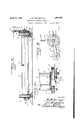
- Figure?) is a view partly in vertical section and partly in-end elevation of the scraper.
- Figure 4c is a view partly in top plan and partly in horizontal section of an end portion of the scraper, and I Figure 5 is a view in end elevation of the truck of the scraper.
- Theaxles 3 and '5 are connected by bars 7 in which the ends of the axles are j ournaled.
- Thefront wheels 4 are larger diametrically than the rear wheels 6 and both the front and rear wheels are: preferably grooved for the reception ofthe rails 8 upon, which the truck is mounted and which extend transversely of the'canal, embankment, road, street or the i like to b'esub-graded;
- the scoop 2 which is of thefresno type, is carried 'by'the truck 1 between the axles 3"and 5, and extends from a point close to one of the rails 8 to a point close to the other of the rails.
- the scoop 2 comprises a bottom wall9, av rear wall 10, and endwalls l li
- the scoop 2 is pivotally connected, as at 12, to the rear axle'5, andis connected to the-front axle 3 by pinions 13 fixed to this axleand rackteeth ldcarried by the front edges Of'llZllG, end walls 11 ofuthe scoop; 1 1 V I
- Therack teeth 141 constantly mesh with the pinions 13,"and are arranged in the arc of. acircle having the rear. axle 5 for its center.”
- the cutting edge 15 of the scoop 2.:ex- I tends-downwardly and forwardly from the bottomof the scoop, and the rack teeth 14.
- a scraper of the character set forth comprising a truck embodying front and rear axles and wheels loose on the axles, a scoop having a cutting edge. means pivotally conmeeting the scoop at its rear side to the rear axle, rack teeth carried by the scoop, pinions fixed to the front axle and meshing with the rack teeth, means for turning the front axle to effect the adjustment of the scoop about its 5 the front axle and meshing with the rack V teeth, a ratchet wheel fixed to the front axle, ratchet wheel turning means, and means engaging the ratchet wheel and one of said bars to secure the front axle against accidental turning movement.
Landscapes
- Engineering & Computer Science (AREA)
- Mechanical Engineering (AREA)
- Mining & Mineral Resources (AREA)
- Civil Engineering (AREA)
- General Engineering & Computer Science (AREA)
- Structural Engineering (AREA)
- Machines For Laying And Maintaining Railways (AREA)
Description
April 12', 1932- R. w. BRIGGS ET AL 1,853,035
SCRAPER FOR SUBGRADING MACHINES Original Filed May 3, 1950 2 Sheets-Sheet l v I I gmmtozs I RIM-BF? S JMSum-m R. W. BRIGGS ET AL SCRAPER FOR SUBGRADII IG MACHINES April 12, 1932.
Original Filed May 3, 1930 2 Sheets-Sheet 2 Patented Apr.,12, 1932 ewe. srArezsz PATENT osrrce ROBERT WEBB muses ,eNn oE. N. SUMMERS, or. 311mm; .TEXAS SCRARER. FOR. SUBGRADIN G MACHINES originaliapplication filed. May 3, 1930; Serial at. 449,480. Divided and this application filed my 23,
This invention relates to the 'gradin'g ma-- chine which forms thesubj e'ct-matter of my copending application filed May 3, 1930, and
serially numbered 449,480, now Patent- No.
.5f'l,818,457, of August '11, 1931, and through the medium of which irrigation and other canals, embanlnnentsproads, streets and the like may be finely sub-gradedfto prepare them for the placement of concrete linings.
The grading machine comprises a truck adapted'for movement in the path located at the side of and parallel to the axis of the canal or the like to be sub-graded, rails at right angles to the axis of the canal'or the like and extending across thetruck and there from into the canal or the like, a wheeled scraper mounted on the rails, means carried by the truck for moving the scraper along the rails in the direction of the truck, and
' means for dumping the scraper when it reaches a position above the truck:
The present invention which constitutes a division of my earlier application, relates to the scraper, and has for one of its objects to provide a device of this character which shall embody a wheeled truck, and a scoop mounted on the truck for adjustment to permit its cutting depth to be regulated and controlled. The invention has for a further object to provide a scraper of the character stated which shall embody means through the medi-' um of which the scoop may be easily and quickly adjusted to regulate its cutting depth and through the medium of which the scoop may be firmly secured in adjusted position. The invention consists in the construction, combination and arrangement of parts hereinafter fully described and claimed, and illustrated in the accompanying drawings,
wherein Figure 1 is a top plan view of the scraper. Figure 2 isa view in rear elevation of the scraper.
Figure?) is a view partly in vertical section and partly in-end elevation of the scraper. Figure 4c is a view partly in top plan and partly in horizontal section of an end portion of the scraper, and I Figure 5 is a view in end elevation of the truck of the scraper.
Serial No. 539,607;
Thefront wheels 4 are larger diametrically than the rear wheels 6 and both the front and rear wheels are: preferably grooved for the reception ofthe rails 8 upon, which the truck is mounted and which extend transversely of the'canal, embankment, road, street or the i like to b'esub-graded; The scoop 2 which is of thefresno type, is carried 'by'the truck 1 between the axles 3"and 5, and extends from a point close to one of the rails 8 to a point close to the other of the rails. The scoop 2, comprises a bottom wall9, av rear wall 10, and endwalls l li The scoop 2 is pivotally connected, as at 12, to the rear axle'5, andis connected to the-front axle 3 by pinions 13 fixed to this axleand rackteeth ldcarried by the front edges Of'llZllG, end walls 11 ofuthe scoop; 1 1 V I Therack teeth 141 constantly mesh with the pinions 13,"and are arranged in the arc of. acircle having the rear. axle 5 for its center." The cutting edge 15 of the scoop 2.:ex- I tends-downwardly and forwardly from the bottomof the scoop, and the rack teeth 14.
extend upwardly from the cutting edge.-
The pinions 13 and the rack teeth 14. provide means through. the medium' of which the scoop@ may be rocked upwardly ahdEdownwardly uponthe rear axle. 5, to the end that the depth of the penetration of the. ground by the cuttingedge 15. of the scoop may be varied. v i v A ratchet wheel 16 :is fixed to one end of the -front axle 3 outwardly of the adjacent front'wheel 4' and end bar 7, and is provided with an annular series of openings 17 which asthe ratchetwheel is turned register re:-
spectively'wi'th' an opening 18 in, said end bar. The ratchet wheel 16--is provided with a l1ub19 through the medium of which it is fixed,.as; at 20,. to the front axle A lever 21 ispivoted at one .end upon the hub 19 out-;
wardly of. the ratchet wheelf16,and it .ex--
tends. from the hub to a point radially beyond the ratchet wheel and the adjacent front wheel 4. The lever 21 is provided at its inner side with a hook 22 which embraces the periphery of the ratchet wheel 16 and which supports a dog 23 for sliding move ment into and out of engagement with the teeth of the ratchet wheel. A finger lever 24 is pivoted, as at 25, to the inner side of the lever 21, and is connected by a rod 26 to the dog 23. A spring 27 positioned between the levers 21 and 24 serves to constantly urge the dog 23 in the direction of the ratchet wheel 16. The ratchet wheel 16, the lever 21, and the dog 23 provide means through the medium of which the front axle 3, and consequently the pinions 13, may be turned to effect the raising or lowering of the cutting edge 15 of the scoop 2.
A pin 28 passing through one of the openings 17 of the ratchet wheel 16 and through the opening 18 of the adjacent end bar 7, serves to secure the scoop 2 in its adjusted position.
In practice, the rails 8, which function as grade guides, are let into the bottom and side of the canal or the like to a depth corresponding to the depth of the ground to be removed to effect the grading operation. The scraper is then moved on the rails 8 to the point where the grading is to be started, and after this has been done the scoop 2 is adjusted to position its cutting edge 15 at the proper position with respect to the bases of the grade rails. The scraper is then moved in the opposite direction on the rails through the medium of the cables 29 which, to effect this operation of the scraper, are wound on drums carried by a truck movable along side the canal or the like, as set forth in my earlier application. When the scraper reaches the point where its load is to be dumped, it may be automatically or manually rocked upward- I ly and forwardly on its front wheels 4. WVhen the scraper is manually dumped it is rocked through the medium of its handle 31.
While we have described the principle of the invention. together with the structure 1 which we now consider the preferred embodiment thereof, it is to be understood that the structure shown is merely illustrative and that such changes may be made, when desired, as fall within the scope of the invention as claimed.
What is claimed is 2- 1. A scraper of the character set forth, comprising a truck embodying front and rear axles and wheels loose on the axles, a scoop having a cutting edge. means pivotally conmeeting the scoop at its rear side to the rear axle, rack teeth carried by the scoop, pinions fixed to the front axle and meshing with the rack teeth, means for turning the front axle to effect the adjustment of the scoop about its 5 the front axle and meshing with the rack V teeth, a ratchet wheel fixed to the front axle, ratchet wheel turning means, and means engaging the ratchet wheel and one of said bars to secure the front axle against accidental turning movement.
3. A scraper of the character set forth, comprising front and rear wheels, an axle carried by the front wheels, a scoop having a cutting edge, means pivotally connecting the scoop at its rear side to the rear wheels, rack teeth carried by the scoop, pinions fixed to the axle and meshing with the rack teeth, means for turning the axle to effect the adjustment of the scoop about its pivot and means for securing the axle against acci- 1 dental turning movement.
In testimony whereof we hereunto aifix our signatures.
ROBERT V. BRIGGS. JOE N. SULIMERS.
Priority Applications (1)
| Application Number | Priority Date | Filing Date | Title |
|---|---|---|---|
| US539607A US1853035A (en) | 1930-05-03 | 1931-05-23 | Scraper for subgrading machines |
Applications Claiming Priority (2)
| Application Number | Priority Date | Filing Date | Title |
|---|---|---|---|
| US449480A US1818457A (en) | 1930-05-03 | 1930-05-03 | Subgrading machine |
| US539607A US1853035A (en) | 1930-05-03 | 1931-05-23 | Scraper for subgrading machines |
Publications (1)
| Publication Number | Publication Date |
|---|---|
| US1853035A true US1853035A (en) | 1932-04-12 |
Family
ID=27035703
Family Applications (1)
| Application Number | Title | Priority Date | Filing Date |
|---|---|---|---|
| US539607A Expired - Lifetime US1853035A (en) | 1930-05-03 | 1931-05-23 | Scraper for subgrading machines |
Country Status (1)
| Country | Link |
|---|---|
| US (1) | US1853035A (en) |
Cited By (1)
| Publication number | Priority date | Publication date | Assignee | Title |
|---|---|---|---|---|
| US9163371B1 (en) * | 2014-12-02 | 2015-10-20 | George Sota | Snow removal system |
-
1931
- 1931-05-23 US US539607A patent/US1853035A/en not_active Expired - Lifetime
Cited By (1)
| Publication number | Priority date | Publication date | Assignee | Title |
|---|---|---|---|---|
| US9163371B1 (en) * | 2014-12-02 | 2015-10-20 | George Sota | Snow removal system |
Similar Documents
| Publication | Publication Date | Title |
|---|---|---|
| US2396287A (en) | Scraper vehicle | |
| US2529208A (en) | Bulldozer attachment | |
| US1853035A (en) | Scraper for subgrading machines | |
| US2363682A (en) | Combined elevator and rock picker | |
| US1078234A (en) | Digging or excavating apparatus. | |
| US1756329A (en) | Road-grading device | |
| US1654685A (en) | Snow-removing apparatus | |
| US1775206A (en) | Scraper | |
| US2192210A (en) | Material loading device for roadway vehicles | |
| US2257761A (en) | Wheeled scraper | |
| US1818457A (en) | Subgrading machine | |
| US1942034A (en) | Road building machine | |
| US1588837A (en) | Road machine | |
| US2825984A (en) | Sidewalk fine graders | |
| US1706742A (en) | Tractor attachment | |
| US2157311A (en) | Scraper | |
| US1786448A (en) | Duplex power scraper | |
| US2291716A (en) | Excavating elevator | |
| US2020938A (en) | Material and article handling machine | |
| US1415880A (en) | Combined grader and material-transporting vehicle | |
| US1629784A (en) | Scarifier | |
| US1093814A (en) | Road drag and grader. | |
| US2174749A (en) | Scraper | |
| US1452260A (en) | Road drag | |
| US1573700A (en) | Machine for use in repairing roads |