US1852997A - Brake mechanism - Google Patents
Brake mechanism Download PDFInfo
- Publication number
- US1852997A US1852997A US142208A US14220826A US1852997A US 1852997 A US1852997 A US 1852997A US 142208 A US142208 A US 142208A US 14220826 A US14220826 A US 14220826A US 1852997 A US1852997 A US 1852997A
- Authority
- US
- United States
- Prior art keywords
- shoes
- brake
- rod
- drum
- brake mechanism
- Prior art date
- Legal status (The legal status is an assumption and is not a legal conclusion. Google has not performed a legal analysis and makes no representation as to the accuracy of the status listed.)
- Expired - Lifetime
Links
Images

Classifications
-
- B—PERFORMING OPERATIONS; TRANSPORTING
- B60—VEHICLES IN GENERAL
- B60T—VEHICLE BRAKE CONTROL SYSTEMS OR PARTS THEREOF; BRAKE CONTROL SYSTEMS OR PARTS THEREOF, IN GENERAL; ARRANGEMENT OF BRAKING ELEMENTS ON VEHICLES IN GENERAL; PORTABLE DEVICES FOR PREVENTING UNWANTED MOVEMENT OF VEHICLES; VEHICLE MODIFICATIONS TO FACILITATE COOLING OF BRAKES
- B60T11/00—Transmitting braking action from initiating means to ultimate brake actuator without power assistance or drive or where such assistance or drive is irrelevant
- B60T11/04—Transmitting braking action from initiating means to ultimate brake actuator without power assistance or drive or where such assistance or drive is irrelevant transmitting mechanically
- B60T11/043—Transmitting braking action from initiating means to ultimate brake actuator without power assistance or drive or where such assistance or drive is irrelevant transmitting mechanically in case of steerable wheels
Definitions
- FREDERICK .H. RAGAN OF SHAKER HEIGHTS, OHIO, ASSIGNOB 'I'O COLUMBIA AXLE GOMBANY, OIE CLEVELAND, OHIO, A, CORPORATION OF. OHIO BRAKE MECHANISM I Originalapplication filed February 12, 1924, Serial No. 692,302. Divided and 1S, 1926. Serial No; 142;.208.
- the present: invention relating, as: indi.- cated, to brake mechanism is more particularly directed toi brake mechanism for use in connection with motor vehicle braking systems'in which brakes are applied to fourwheels, including the steering wheels,which are -mounted to oscillate about substantially vertical axes.
- the principal object of the invention is the provision of. a'sirnple, inexpensive brakesystem of the type which can be economically manufactured.
- the present 2 application is division of my co-pending application Serial No. 692,302, filedFebruary 12,1924, which hasmatured into Patent No. 1,608,405,0ct0ber 1 9, 1926.
- Fig.2 is a firmt elevation of thesameshowing brake mechanism and 'endi'of the axle in section;
- 3 is'a frontelevation of the brake drum and shoes and means for operating the same Fig; 49is; a horizontal sec tion with the brake operating-"means, this view being-tan enlargeinent of 'theviewof the" brake mechanism shown in Fig; '1';
- Fig. 7 is a view similar t6 Fig. 2, butshowinga modification of the operating means-there 1 shown;
- FigQIFis' a plan-View of'ai-modi'fifcation this application filed- October elevation showing a modified type of brake shoe construction and mounting therefor;
- Fig. 13 is a sectionon; the line 13-18;
- axle member 1 I which; represents the front axle of a motor vehicle, this member being provided with the usual ofi set end portion 2 formed. with an opening 3 therethrough at. a slight angle to a vertical plane.
- the-adjacent lower ends of the brake shoes 10 and'll are provided with swear plates 20'and 21', haying beveled or con-x verging adj acen'tsurfaces22anct 23',- and being of cylindrical outline. These surfaces are engaged by means of a ball-shaped member adjustably connected to a rod 26 which is movable substantially longitudinally of the axle member 1. lVhen the member 25 is moved outwardly, that is toward the outer portion of the wheel the spherical surface of the faced-off ball 25 wedges apart the lower ends of the shoes 10 and 11 and forces the same into engagement with the drum.
- Figs. 7, 8 and 9 I have shown a modification of the above means, in which the brake shoes consist of two semi-circular members and 41, normally held in the position shown in Fig. 8, that is, out of engagement with the brake drum by means of a tension spring 42.
- These two shoes 40 and 41 have their upper adjacent ends formed with parallel substantially radial flanges 44 and 45 contacting against two cams or eccentrics 46 and 47, respectively.
- the two cams are connected by a shaft or stud 48 extending through the dust plate 49 of the brake drum, and being firmly mounted in an anchor brake 50 at either end.
- One of the cams extends to one side of the central plane of the shaft 48 and engages the flange 44 of the shoe 40, and the other cam extends in the opposite direction and engages against the flanges 45 on the shoe 41.
- Rotation of the shaft 48 which may be effected by rotating the square end 51 of the bolt, will space apart the two ends 44 and 45 of the two shoes.
- Rotation of the shaft 48 may be effected after a nut 53 has first been moved sufiiciently to allow a washer 54, provided with a projection 55, to be swung out of its engagement with one of the openings 56 formed in a circumferential series in the dust cap.
- the washer 54 is allowed to snap back into the nearest recess 55, and the nut 53 is then turned down to hold the bolt and cams in the desired position.
- the means for operating the shoes of the present construction consist of a longitudinally movable rod 60 adjustably connected to a socket 61, which is formed with two yoked arms 62 and 63 positioned between the adjacent lower ends 64 and 65 of the shoes.
- a stud 66 upon which are rotatably mounted rollers 67 68 and 69. These rollers engage in corresponding recesses in the ends of the wear plates 70 and 71, secured respectively to the ends of the shoes 40 and 41.
- the operation of the above described brake actuating means is similar to the operation previously described and shown in Figs. 1 and 6.
- the longitudinally movable rod 26 (see Figs. 1 and 2) is provided. with an offset portion 80, allowing the inner portion of the rod to lie in a plane behind the vertical plane of the axle 1.
- the rod 26 (or the rod 60 in the form of Fig. 7) is connected to one end of a lever 81, which is pivoted about a vertical axis in a bracket 82 mounted on the axle.
- this link 81 On the other end of this link 81 there is correspondingly attached a second rod 26 extending to the brakes in the other wheel.
- the plate 81 is also provided with an arm 83, to which is attached a rod 84, which may be carried to the brake foot pedal, so that longitudinal movement of the rod 84 will rock the plate 81 and move the levers 26 and 26 in opposite directions to apply the brake shoes in either wheel.
- the lever 81 has a slot 140 extending in a plane parallel to rods 26, 26, which allows slight longitudinal movement of the lever to equalize the pull on the two rods.
- Adjustment for wear between the wear plates on the lower ends of the brake shoes, and either the ball or roller operating members of the two types shown, can be readily effected by releasing the nut 36 on the end of the rod 26, and then securing the end of the ball member 25 outwardly a suflicient distance.
- the same adjustment may be made in the construction of F i 7, except that here the adjustment is made y detaching the inner end of the rod 60 from its connection to the plate 81, and then turning this rod while leaving the socket and yoke 61 in their orig-- inal angular position.
- the present brake mechanism is extremely simple in its construction, and has the particular advantage of not requiring close limits between the various ports, since the adjustments provided can be utilized to take up for the usual manufacturing tolerances in the final assembly of the mechanism without affecting in any way the even and uniform application of the brake mechanism.
- Fig. 10 I have shown a modification of the brake actuating means, here shown to consist of a longitudinally movable bar or rod 90, having a forked end 91, between the two parts of which is pivotally mounted a pressed steel wedge member 92.
- This wedge member 92 may be economically formed out of sheet metal and may be readily mounted on the end of the rod 91 by means of a pin 93. It operates against rollers 94 carried in ation of the rods 26, 26'.
- levers 96 and 96' which are oscillatorily mounted on a bracket 97 about" pins 98 and 98.
- the other ends of the two levers 96 and 96' are provided with pins 99 and 99 which are received in slots 100 and 100 in a connecting bar 101 mounted directly over the axle 1.
- a rod 102 is connected to the center of the transverse bar 101, and movement of the rod 102 in the direction'of the arrow causes oscillation of the lever 96 in a counterclockwise direction, and of the lever 96 in a clockwise direction, thus drawing the rod 26 and 26 together and applying the brakes. Any inequalities in the applica tion of the pressure are equalized through the floating connection between the two levers 96 and 96 and the bar 101.
- the direction of movement of the rod 102 depends upon whether the equalizing mechanism foroperating the longitudinally movable rods is employed with end members of the type shown in Figs. 1 to 5, inclusive, or of the type shown in Figs. 7 to 10, inclusive.
- Thismechanism' includes a screw or: bolt 120 having right'andlefthand threaded portions 121 and 122 respectively engagingwiththe adjusting disks 110 and 110
- the plates '1-07, which engage-in the. slots 109 and 109 i-nzthe disksarebeveled as indicated-inthis figure, so that.
- any rotation ofthe belt 120 which will bring'thetwo disks nearer together-:willaforce: apart the two plates10'Z and also'oficourse the two shoes 105 and 105.
- the slots 114 are of suffitime length. to permit ofadjustment ofthe initial position of the shoes to take up for wear. on. the brake bands: without bringing the adjusting screws 111 into contact with the ends of the slot...
- the adjusting means just described have shoes on mechanism which will permit of abodily floating of the shoes into engagement with the drum. When applied, one of the shoes is anchored against the operating mech anism previously described. while the other shoe anchors itself against thedisks 110 and 110.
- shoes mounted adjacent the periphery of said drum, actuating means disposed between adjacent ends of said shoes for moving the same into en agement with said drum, a djusting means disposed between the other adjacent ends of said shoes, said means includi ing pair of spaced non-rotatable elements having converging surfaces slidably engaging said shoes, and means adj ustably connecting said elements.
- a brake drum two shoes mounted adjacent the periphery of said drum, actuating means disposed between adjacent ends of said shoes for moving the same into engagement with said drum, adjusting means disposed between the other adjacent ends of said shoes, said adjusting means including spaced non-rotatable elements having converging surfaces, and said adjusting means having a .slidable engagement with said shoes, and a right and left screw adjustably engaging said elements.
- a brake comprising, in combination, shoes having oppositely-inclined wedge surfaces at adjacent ends, two pairs of opposite Wedge members having surfaces engaging the oppositely-inclined surfaces, and a rightand-left threaded member for adjusting the four wedge members simultaneously.
Landscapes
- Engineering & Computer Science (AREA)
- Transportation (AREA)
- Mechanical Engineering (AREA)
- Braking Arrangements (AREA)
Description
BRAKE MECHANI SM Original Filed Feb. 12, 1924 4 Sheets-Sheet 1 Fig.1.
O Us. Fig.3.
6 0 I INVENTOR 1 FTedericK H. Ragan ATTO NEYS.
BRAKE MECHANISM ori ina Fned Feb. 12, 1924 4 Sheets-Sheet 2 a1 is 36 as IN VEN TOR.
fredericH H. Regan AT NEYS F. H. RAGAN 1,852,997
F. H. RAGAN BRAKE MECHANISM April 5, 1932' Original Filed Feb. 12, 1924 4 Sheets-Sheet 3 INVENTOR. Frederick H.RQ%Q\'I 14 ATTOR27EYS Patented Apr. 5, 1932 srrArsisn 'r; mes.
FREDERICK .H. RAGAN, =OF SHAKER HEIGHTS, OHIO, ASSIGNOB 'I'O COLUMBIA AXLE GOMBANY, OIE CLEVELAND, OHIO, A, CORPORATION OF. OHIO BRAKE MECHANISM I Originalapplication filed February 12, 1924, Serial No. 692,302. Divided and 1S, 1926. Serial No; 142;.208.
The present: invention, relating, as: indi.- cated, to brake mechanism is more particularly directed toi brake mechanism for use in connection with motor vehicle braking systems'in which brakes are applied to fourwheels, including the steering wheels,which are -mounted to oscillate about substantially vertical axes. The principal object of the invention is the provision of. a'sirnple, inexpensive brakesystem of the type which can be economically manufactured. The present 2 application is division of my co-pending application Serial No. 692,302, filedFebruary 12,1924, which hasmatured into Patent No. 1,608,405,0ct0ber 1 9, 1926.
To-the accomplishment of the foregoing and related ends, said invention, then, con.- sists of the meanshereinafter fully described and particularly pointed out in the claims;
'the anner-eddrawings and the: following deseription setting forth in detail c'erta-in mechanismembodying the' invention, such disclosed means constituting, however, but one of various mechanical forms in which the principle of the invention may-be used.
In said'annexed drawings:
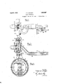
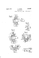
Fig. 1-1 is a plan view showing one portion of afront a-x-le' ofavehicle, together'with the brake mechanism therefor, the brake mechanism being'= partially in 'section; Fig.2 is a firmt elevation of thesameshowing brake mechanism and 'endi'of the axle in section; 3 is'a frontelevation of the brake drum and shoes and means for operating the same Fig; 49is; a horizontal sec tion with the brake operating-"means, this view being-tan enlargeinent of 'theviewof the" brake mechanism shown in Fig; '1'; Fig; 5-is aview similar to Fig.: 4:, but's'howing the relation of the-shoes and operating means in a dilferent'angular posltronofthe-fonmer; Fig. 6'1s'a sectlonon thel ine6 6 in-52 Fig.7 isa view similar t6 Fig. 2, butshowinga modification of the operating means-there 1 shown; Fig. 85' is a frontelevationofthe brake'me chanismshown in Fig? 'fi Fig: 9 is ahorizontal section on 'the'line Fig. 7,-Fig; 1O is -a plan view of 'a modification of'thebrake joperatingmem ber l; FigQIFis' a plan-View of'ai-modi'fifcation this application filed- October elevation showing a modified type of brake shoe construction and mounting therefor;
and Fig. 13 is a sectionon; the line 13-18;
Fig. 12, showing the means for adjusting the normal position of the brake shoes.-
Referring now to Figs. 1, 2 and 3 thereis I shown an axle member 1 I which; represents the front axle ofa motor vehicle, this member being provided with the usual ofi set end portion 2 formed. with an opening 3 therethrough at. a slight angle to a vertical plane.
. this opening?) there is mounted a pivot gularly formed ends in which are oscillator- 1 ily-mounted pins 1 2 and 13;: These pins are slotted and are engagedin suoh slots by means of a ring member or plate 14,-which is shown in section in Fig. 6,-and which nlay be moved transversely of the plane of the shoes by-means of a boltf16 and 111N717 there on to adjust'the spacingbetween the ends of the brake shoes, this bolt 16 -being received in an'anchor bracketlS, which is'fixed inthe dust .cap1'9 carried on the spindle. It will beevident that upon spreading the other ends of the two brake shoes-the latter will rock about the pins 12 and'13 and move into engagement with the flange 9 onthe drum the shoes bein rovided with suitable friction Them-eans for actuating thebra'lre shoes i 'are shown in Figs. 1, 2,14 and 5, while a modified type of actuatingmeansis shown in Figs. 7, 8' and 9. *Inthe firstfform, in
Figs. 1, 2and 3, the-adjacent lower ends of the brake shoes 10 and'll are provided with swear plates 20'and 21', haying beveled or con-x verging adj acen'tsurfaces22anct 23',- and being of cylindrical outline. These surfaces are engaged by means of a ball-shaped member adjustably connected to a rod 26 which is movable substantially longitudinally of the axle member 1. lVhen the member 25 is moved outwardly, that is toward the outer portion of the wheel the spherical surface of the faced-off ball 25 wedges apart the lower ends of the shoes 10 and 11 and forces the same into engagement with the drum. lVhen the wheel is oscillated about its axis, which is the center line of the pin 4, the ball remains in contact with the two wear plates on the lower ends of the shoes, the position of which is that shown in dotted lines in Fig. 5. Upon movement of the rod 26 the ball will then act as before to spread the two shoes apart and engage both of them with the brake drum. Upon the release of the rod 20 the shoes are returned to their normal position by means of a coil spring 28 and a bolt-shaped flat spring 29 mounted on a plate 30 secured to the dust plate or cover 19. This spring 29 has two curved ends 31 and 32 engaging in suitable slots in the lower ends of the brake shoes, as shown in Fig. 3.
In Figs. 7, 8 and 9 I have shown a modification of the above means, in which the brake shoes consist of two semi-circular members and 41, normally held in the position shown in Fig. 8, that is, out of engagement with the brake drum by means of a tension spring 42. These two shoes 40 and 41 have their upper adjacent ends formed with parallel substantially radial flanges 44 and 45 contacting against two cams or eccentrics 46 and 47, respectively. The two cams are connected by a shaft or stud 48 extending through the dust plate 49 of the brake drum, and being firmly mounted in an anchor brake 50 at either end. One of the cams extends to one side of the central plane of the shaft 48 and engages the flange 44 of the shoe 40, and the other cam extends in the opposite direction and engages against the flanges 45 on the shoe 41. Rotation of the shaft 48, which may be effected by rotating the square end 51 of the bolt, will space apart the two ends 44 and 45 of the two shoes. Rotation of the shaft 48 may be effected after a nut 53 has first been moved sufiiciently to allow a washer 54, provided with a projection 55, to be swung out of its engagement with one of the openings 56 formed in a circumferential series in the dust cap. When the desired adjustment has been made, the washer 54 is allowed to snap back into the nearest recess 55, and the nut 53 is then turned down to hold the bolt and cams in the desired position.
The means for operating the shoes of the present construction consist of a longitudinally movable rod 60 adjustably connected to a socket 61, which is formed with two yoked arms 62 and 63 positioned between the adjacent lower ends 64 and 65 of the shoes.
Vertically disposed in the two arms 62 and 63, is a stud 66, upon which are rotatably mounted rollers 67 68 and 69. These rollers engage in corresponding recesses in the ends of the wear plates 70 and 71, secured respectively to the ends of the shoes 40 and 41. The operation of the above described brake actuating means is similar to the operation previously described and shown in Figs. 1 and 6.
In both types of my construction the longitudinally movable rod 26 (see Figs. 1 and 2) is provided. with an offset portion 80, allowing the inner portion of the rod to lie in a plane behind the vertical plane of the axle 1. At its inner end the rod 26 (or the rod 60 in the form of Fig. 7) is connected to one end of a lever 81, which is pivoted about a vertical axis in a bracket 82 mounted on the axle. On the other end of this link 81 there is correspondingly attached a second rod 26 extending to the brakes in the other wheel. The plate 81 is also provided with an arm 83, to which is attached a rod 84, which may be carried to the brake foot pedal, so that longitudinal movement of the rod 84 will rock the plate 81 and move the levers 26 and 26 in opposite directions to apply the brake shoes in either wheel. The lever 81 has a slot 140 extending in a plane parallel to rods 26, 26, which allows slight longitudinal movement of the lever to equalize the pull on the two rods.
Adjustment for wear between the wear plates on the lower ends of the brake shoes, and either the ball or roller operating members of the two types shown, can be readily effected by releasing the nut 36 on the end of the rod 26, and then securing the end of the ball member 25 outwardly a suflicient distance. The same adjustment may be made in the construction of F i 7, except that here the adjustment is made y detaching the inner end of the rod 60 from its connection to the plate 81, and then turning this rod while leaving the socket and yoke 61 in their orig-- inal angular position. The present brake mechanism is extremely simple in its construction, and has the particular advantage of not requiring close limits between the various ports, since the adjustments provided can be utilized to take up for the usual manufacturing tolerances in the final assembly of the mechanism without affecting in any way the even and uniform application of the brake mechanism.
In Fig. 10 I have shown a modification of the brake actuating means, here shown to consist of a longitudinally movable bar or rod 90, having a forked end 91, between the two parts of which is pivotally mounted a pressed steel wedge member 92. This wedge member 92 may be economically formed out of sheet metal and may be readily mounted on the end of the rod 91 by means of a pin 93. It operates against rollers 94 carried in ation of the rods 26, 26'.
outer ends of levers 96 and 96', which are oscillatorily mounted on a bracket 97 about" pins 98 and 98. The other ends of the two levers 96 and 96' are provided with pins 99 and 99 which are received in slots 100 and 100 in a connecting bar 101 mounted directly over the axle 1. A rod 102 is connected to the center of the transverse bar 101, and movement of the rod 102 in the direction'of the arrow causes oscillation of the lever 96 in a counterclockwise direction, and of the lever 96 in a clockwise direction, thus drawing the rod 26 and 26 together and applying the brakes. Any inequalities in the applica tion of the pressure are equalized through the floating connection between the two levers 96 and 96 and the bar 101.
The direction of movement of the rod 102 depends upon whether the equalizing mechanism foroperating the longitudinally movable rods is employed with end members of the type shown in Figs. 1 to 5, inclusive, or of the type shown in Figs. 7 to 10, inclusive.
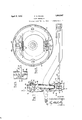
If employed withthe end members shown in Figs. 1 to 5, inclusive, which includes the ball end 25, then the rod 102 is pulled in a direc- .tion correspondingto the upward direction 011 the drawing in Fig. 1. If, the mechanism shown in Figs. 7, 8, 9 and 10 is employed the rod 102 must be pushed downwardly (as shown on the drawing Fig. 1) to effect oper- In Figs. 12 and 13 I have shown a modified type of brake shoe, in which the inner ends of the'brake shoe members 105, 105' are provided with spacedplates 106, 106. Between the "adjacent ends of the plates 105 and 106 and 105 and 106 are secured short plates 107, 107 which are loosely supported in recesses 109 and 109 formed in two spaced parallel disks 110 and 110', (see F 13). The initial or inoperative position of the brake shoe in this construction may be adjusted by means of an adjusting screw 111 carried in a bracket 112, which is secured to the dust plate or spindle. This screw is pro-- vided with a reduced end portion 113, which is received in a slot 114, in the plate 106. A
The adjusting means just described have shoes on mechanism which will permit of abodily floating of the shoes into engagement with the drum. When applied, one of the shoes is anchored against the operating mech anism previously described. while the other shoe anchors itself against thedisks 110 and 110.
the advantage of being extremely simple in I Othermodes of applying the principle of my invention may be employed instead of the one explained. change being made as regards the mechanism herein d sclosed. provided the means stated by any of the following claims or the equivalent of such-stated means he employed.
I therefore particularly point out and distinctlv claim as my invention 1. In mechanism of the character described. the combination of a brake drum, two
shoes mounted adjacent the periphery of said drum, actuating means disposed between adjacent ends of said shoes for moving the same into en agement with said drum, a djusting means disposed between the other adjacent ends of said shoes, said means includi ing pair of spaced non-rotatable elements having converging surfaces slidably engaging said shoes, and means adj ustably connecting said elements.
2. In mechanism of the character de scribed, the combination of a brake drum, two shoes mounted adjacent the periphery of said drum, actuating means disposed between adjacent ends of said shoes for moving the same into engagement with said drum, adjusting means disposed between the other adjacent ends of said shoes, said adjusting means including spaced non-rotatable elements having converging surfaces, and said adjusting means having a .slidable engagement with said shoes, and a right and left screw adjustably engaging said elements.
3. A brake comprising, in combination, shoes having oppositely-inclined wedge surfaces at adjacent ends, two pairs of opposite Wedge members having surfaces engaging the oppositely-inclined surfaces, and a rightand-left threaded member for adjusting the four wedge members simultaneously.
Signed by me this 16th day of October,
FREDERICK H. RAGAN.
Priority Applications (1)
| Application Number | Priority Date | Filing Date | Title |
|---|---|---|---|
| US142208A US1852997A (en) | 1924-02-12 | 1926-10-18 | Brake mechanism |
Applications Claiming Priority (2)
| Application Number | Priority Date | Filing Date | Title |
|---|---|---|---|
| US692802A US1603405A (en) | 1924-02-12 | 1924-02-12 | Brake mechanism |
| US142208A US1852997A (en) | 1924-02-12 | 1926-10-18 | Brake mechanism |
Publications (1)
| Publication Number | Publication Date |
|---|---|
| US1852997A true US1852997A (en) | 1932-04-05 |
Family
ID=26839870
Family Applications (1)
| Application Number | Title | Priority Date | Filing Date |
|---|---|---|---|
| US142208A Expired - Lifetime US1852997A (en) | 1924-02-12 | 1926-10-18 | Brake mechanism |
Country Status (1)
| Country | Link |
|---|---|
| US (1) | US1852997A (en) |
-
1926
- 1926-10-18 US US142208A patent/US1852997A/en not_active Expired - Lifetime
Similar Documents
| Publication | Publication Date | Title |
|---|---|---|
| US1978974A (en) | Disk brake | |
| US2064103A (en) | Cam assembly for brakes | |
| US1852997A (en) | Brake mechanism | |
| US2251854A (en) | Internal shoe drum brake | |
| US1761933A (en) | Internal brake | |
| US3265165A (en) | Brake shoe mounting | |
| US1603405A (en) | Brake mechanism | |
| US1959878A (en) | Brake mechanism for vehicles | |
| US1913156A (en) | Internal band brake | |
| US2060429A (en) | Brake mechanism | |
| US1834530A (en) | Brake applying means | |
| US2788866A (en) | Adjusting mechanism for servo brakes, particularly for motor vehicles | |
| US1885174A (en) | Brake mechanism | |
| US1980512A (en) | Vehicle brake | |
| US1876934A (en) | Brake mechanism | |
| US1619039A (en) | Brake | |
| US1798936A (en) | Front-wheel brake | |
| US1641443A (en) | Brake | |
| US2006522A (en) | Brake | |
| US2040202A (en) | Vehicle brake | |
| US2770328A (en) | Brake assembly | |
| US2041492A (en) | Brake | |
| US1762290A (en) | Brake control | |
| US1609106A (en) | Brake | |
| US1880477A (en) | Vehicle brake |