US1852975A - Poultry waterer - Google Patents
Poultry waterer Download PDFInfo
- Publication number
- US1852975A US1852975A US533271A US53327131A US1852975A US 1852975 A US1852975 A US 1852975A US 533271 A US533271 A US 533271A US 53327131 A US53327131 A US 53327131A US 1852975 A US1852975 A US 1852975A
- Authority
- US
- United States
- Prior art keywords
- trough
- tank
- water
- valve
- spring
- Prior art date
- Legal status (The legal status is an assumption and is not a legal conclusion. Google has not performed a legal analysis and makes no representation as to the accuracy of the status listed.)
- Expired - Lifetime
Links
- 244000144977 poultry Species 0.000 title description 3
- XLYOFNOQVPJJNP-UHFFFAOYSA-N water Substances O XLYOFNOQVPJJNP-UHFFFAOYSA-N 0.000 description 12
- 230000008014 freezing Effects 0.000 description 2
- 238000007710 freezing Methods 0.000 description 2
- 238000010438 heat treatment Methods 0.000 description 2
- 238000002485 combustion reaction Methods 0.000 description 1
- 230000035622 drinking Effects 0.000 description 1
- 239000003651 drinking water Substances 0.000 description 1
- 235000020188 drinking water Nutrition 0.000 description 1
- 238000005192 partition Methods 0.000 description 1
Images

Classifications
-
- A—HUMAN NECESSITIES
- A01—AGRICULTURE; FORESTRY; ANIMAL HUSBANDRY; HUNTING; TRAPPING; FISHING
- A01K—ANIMAL HUSBANDRY; AVICULTURE; APICULTURE; PISCICULTURE; FISHING; REARING OR BREEDING ANIMALS, NOT OTHERWISE PROVIDED FOR; NEW BREEDS OF ANIMALS
- A01K39/00—Feeding or drinking appliances for poultry or other birds
- A01K39/02—Drinking appliances
- A01K39/022—Drinking appliances with weight-controlled supply
-
- Y—GENERAL TAGGING OF NEW TECHNOLOGICAL DEVELOPMENTS; GENERAL TAGGING OF CROSS-SECTIONAL TECHNOLOGIES SPANNING OVER SEVERAL SECTIONS OF THE IPC; TECHNICAL SUBJECTS COVERED BY FORMER USPC CROSS-REFERENCE ART COLLECTIONS [XRACs] AND DIGESTS
- Y10—TECHNICAL SUBJECTS COVERED BY FORMER USPC
- Y10T—TECHNICAL SUBJECTS COVERED BY FORMER US CLASSIFICATION
- Y10T137/00—Fluid handling
- Y10T137/7287—Liquid level responsive or maintaining systems
- Y10T137/7339—By weight of accumulated fluid
- Y10T137/7355—In gravitating tank
Definitions
- WITNESS ATTORNEY Patented. Apr. ⁇ 5,' 1932 UIN-1frz-I;ofr STATES rsszns;
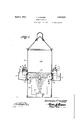
- Figure 1 is a vertical sectional view of a tank with the Watering device applied thereto.
- Figure 2 is a perspective view of the trough of the watering device.
- Figure 3 is an enlarged sectional view of the-trough and adj acent parts ofthe tank.
- the watering devicev comprises a tank ,1
- the tank 1 is provided with one or more spigots 2 each having a valve 3 for controlling the flow of water through the spigots.
- An arm t is located upon each spigot and a spring 5 is interposed between the arm and the valve 3 and serves to hold the valve in a closed position upon the spigots.
- a rod 6 depends from the free end of the valve 3 and the lower end of the said rod rests upon the bottomy of the trough 7 when the said trough is at an elevated position as shown at the left in Figure 1 of the drawings.
- the trough 7 is provided with a ange 8 o which is adapted to engage over hooks 9 provided at the side of the tank.
- the flange 8 provided with a leafportion 10 adapted to lie at'the side of the tank.
- a spring 11 is interposed between the rear wall of the trough and the leaf portion 10.
- a screw 12 passes through the ywall of the tank and engages the end of the .leaf portion 10.r
- the spring l1 is an expansion spring and serves to hold the side of the trough Aat an? angle to the leaf 10 when ythe trough is empty, or nearly so, as shown at the left in Figure 1 of the drawings.
- the flange 8 may flex or bend under the influence of the spring 11 or the weight of the water in the trough.
- the interior of the tank 1 is divided by a partition wall 13 into a water chamber 14 and a heating chamberl.
- the side -walls of the heating chamber 15 are ⁇ provided with openingsl. These openings 16 are located below the spigots which communicate ywith the interior of the water chamber.
- a lampy 17 or other heater may be placed in the chamber 15 and when lighted the heat ascends and strikes the partitionwall 13 thus keeping the water in the chamber 14 from freezing and as the products of combustion escape from the chamber 15 through the openings 16 they pass 1 aroundspigots 2 and prevent the water in the spigots from freezing.
- a poultry waterer comprising a tank having a spigot, a valve for controllingthe flow of water through the spigot, a rod attached to the valve, a trough having at its edge a liange, supporting means .for engaging the flange of the trough, and a spring bearing against the side of the trough and adapted to hold the bottom thereof toward the rod.
Landscapes
- Life Sciences & Earth Sciences (AREA)
- Environmental Sciences (AREA)
- Birds (AREA)
- Animal Husbandry (AREA)
- Biodiversity & Conservation Biology (AREA)
- Processing Of Meat And Fish (AREA)
- Housing For Livestock And Birds (AREA)
Description
April 5, 1932.
H. KRATZ'ER 1,852,975
POULTRY WATERER Filed April 27, 193]b 2 Sheets-Sheet l INVENTOR 0 ATTORNEY April 5, 1932. H. KRATZER 1,852,975
POULTIH WATERER Filed April 27, 1931 2 Sheets-sheet 2 INVENTOR j? BY @ed 62,-
WITNESS: ATTORNEY Patented. Apr.` 5,' 1932 UIN-1frz-I;ofr STATES rsszns;
FAn-:Nr orFlcE` HERMAN `KRATZER,` F ELLSWORTH,v KANSAS Poor/.URY waarnaar;
Application led Apri1r27, 1931. Serial No. 533,271.
10 ply tank so associated and arranged that the tank will be charged to automatically discharge into the trough at proper intervals for replenishing the drinking water therein merelyv upon the elevation of the bottom of the drinking trough.
In the accompanying drawings Figure 1 is a vertical sectional view of a tank with the Watering device applied thereto.
Figure 2 is a perspective view of the trough of the watering device.
Figure 3 is an enlarged sectional view of the-trough and adj acent parts ofthe tank.
As illustrated in the accompanying drawings the watering devicev comprises a tank ,1
of usual form and adapted to hold a quantity of water. The tank 1 is provided with one or more spigots 2 each having a valve 3 for controlling the flow of water through the spigots. An arm t is located upon each spigot and a spring 5 is interposed between the arm and the valve 3 and serves to hold the valve in a closed position upon the spigots.
A rod 6 depends from the free end of the valve 3 and the lower end of the said rod rests upon the bottomy of the trough 7 when the said trough is at an elevated position as shown at the left in Figure 1 of the drawings.
d The trough 7 is provided with a ange 8 o which is adapted to engage over hooks 9 provided at the side of the tank. The flange 8 provided with a leafportion 10 adapted to lie at'the side of the tank. A spring 11 is interposed between the rear wall of the trough and the leaf portion 10. A screw 12 passes through the ywall of the tank and engages the end of the .leaf portion 10.r
When the-trough`7 is empty or contains but little'water the bottom thereof is elevated as shown at the left in Figure 1 of the draw ings and the rod 6 is moved in an upward direction whereby the valve 3 is opened and watery mayjflow from the tank 1 through the spigots into the trough 7.'` When the trough c 7 becomes filled with water it swings down to the. position as shown at lthe right in Figure f 1 of the drawings whereby the lower end of the rod 6 is spaced abovek the bottom lof the trough and the tension of the spring 5 comes into play thereby closing the valve 3 down upon the spigot y2 and thus interrupting the liow of water from the tank into the trough. l As the water is consumed from the trough y the operation of refilling as above described is repeated. The spring l1 is an expansion spring and serves to hold the side of the trough Aat an? angle to the leaf 10 when ythe trough is empty, or nearly so, as shown at the left in Figure 1 of the drawings. The flange 8 may flex or bend under the influence of the spring 11 or the weight of the water in the trough. v
The interior of the tank 1 is divided by a partition wall 13 into a water chamber 14 and a heating chamberl. The side -walls of the heating chamber 15 are `provided with openingsl. These openings 16 are located below the spigots which communicate ywith the interior of the water chamber. A lampy 17 or other heater may be placed in the chamber 15 and when lighted the heat ascends and strikes the partitionwall 13 thus keeping the water in the chamber 14 from freezing and as the products of combustion escape from the chamber 15 through the openings 16 they pass 1 aroundspigots 2 and prevent the water in the spigots from freezing.
Having described the invention what is claimed is A poultry waterer comprising a tank having a spigot, a valve for controllingthe flow of water through the spigot, a rod attached to the valve, a trough having at its edge a liange, supporting means .for engaging the flange of the trough, and a spring bearing against the side of the trough and adapted to hold the bottom thereof toward the rod.
In testimony whereof I affix my signature.
HERMAN KRATZER. n
Priority Applications (1)
| Application Number | Priority Date | Filing Date | Title |
|---|---|---|---|
| US533271A US1852975A (en) | 1931-04-27 | 1931-04-27 | Poultry waterer |
Applications Claiming Priority (1)
| Application Number | Priority Date | Filing Date | Title |
|---|---|---|---|
| US533271A US1852975A (en) | 1931-04-27 | 1931-04-27 | Poultry waterer |
Publications (1)
| Publication Number | Publication Date |
|---|---|
| US1852975A true US1852975A (en) | 1932-04-05 |
Family
ID=24125228
Family Applications (1)
| Application Number | Title | Priority Date | Filing Date |
|---|---|---|---|
| US533271A Expired - Lifetime US1852975A (en) | 1931-04-27 | 1931-04-27 | Poultry waterer |
Country Status (1)
| Country | Link |
|---|---|
| US (1) | US1852975A (en) |
Cited By (3)
| Publication number | Priority date | Publication date | Assignee | Title |
|---|---|---|---|---|
| US2659347A (en) * | 1951-07-31 | 1953-11-17 | Ralston Purina Co | Automatic poultry drinking fountain |
| US2879743A (en) * | 1956-09-17 | 1959-03-31 | Hostetler Eldon | Liquid dispensing device |
| US4448210A (en) * | 1983-05-20 | 1984-05-15 | The Dow Chemical Company | Apparatus and method for controlling the level of a liquid in a tank |
-
1931
- 1931-04-27 US US533271A patent/US1852975A/en not_active Expired - Lifetime
Cited By (3)
| Publication number | Priority date | Publication date | Assignee | Title |
|---|---|---|---|---|
| US2659347A (en) * | 1951-07-31 | 1953-11-17 | Ralston Purina Co | Automatic poultry drinking fountain |
| US2879743A (en) * | 1956-09-17 | 1959-03-31 | Hostetler Eldon | Liquid dispensing device |
| US4448210A (en) * | 1983-05-20 | 1984-05-15 | The Dow Chemical Company | Apparatus and method for controlling the level of a liquid in a tank |
Similar Documents
| Publication | Publication Date | Title |
|---|---|---|
| US1852975A (en) | Poultry waterer | |
| US1113887A (en) | Feed and water reservoir. | |
| US2490319A (en) | Liquid fuel regulator | |
| US669415A (en) | Stock-waterer. | |
| US1029623A (en) | Chicken-feeder. | |
| US1174766A (en) | Fluid-feeding device. | |
| US1220404A (en) | Stock-watering device. | |
| US1643245A (en) | Poultry fountain | |
| US2517865A (en) | Adjustable poultry watering trough | |
| US1380321A (en) | Air-moistening structure for hot-air furnaces | |
| US1477411A (en) | Stock-watering trough | |
| US1254937A (en) | Hog-watering apparatus. | |
| US2466135A (en) | Watering fountain | |
| US1522004A (en) | Watering trough | |
| US1319567A (en) | Hog-waterer | |
| US1018357A (en) | Incubator. | |
| US1797996A (en) | Water trough | |
| US1269874A (en) | Poultry drinking-fountain. | |
| US1662716A (en) | Regulating valve for water troughs | |
| US2297379A (en) | Animal operated stock-watering trough | |
| US1052631A (en) | Stock and poultry drinking-fountain. | |
| US2664070A (en) | Stock waterer | |
| US508492A (en) | Incubator | |
| US436082A (en) | Automatic stock-waterer | |
| US1716239A (en) | Poultry watering trough |