US1852969A - Gravity discharge grain bin for harvesters - Google Patents
Gravity discharge grain bin for harvesters Download PDFInfo
- Publication number
- US1852969A US1852969A US314825A US31482528A US1852969A US 1852969 A US1852969 A US 1852969A US 314825 A US314825 A US 314825A US 31482528 A US31482528 A US 31482528A US 1852969 A US1852969 A US 1852969A
- Authority
- US
- United States
- Prior art keywords
- bin
- bars
- harvesters
- grain bin
- grain
- Prior art date
- Legal status (The legal status is an assumption and is not a legal conclusion. Google has not performed a legal analysis and makes no representation as to the accuracy of the status listed.)
- Expired - Lifetime
Links
- 230000005484 gravity Effects 0.000 title description 7
- 241001124569 Lycaenidae Species 0.000 title description 3
- 238000003306 harvesting Methods 0.000 description 10
- 239000012530 fluid Substances 0.000 description 8
- 238000010276 construction Methods 0.000 description 2
- 101100001674 Emericella variicolor andI gene Proteins 0.000 description 1
- 230000000694 effects Effects 0.000 description 1
- 230000001771 impaired effect Effects 0.000 description 1
- 230000001788 irregular Effects 0.000 description 1
- 238000007789 sealing Methods 0.000 description 1
Images

Classifications
-
- A—HUMAN NECESSITIES
- A01—AGRICULTURE; FORESTRY; ANIMAL HUSBANDRY; HUNTING; TRAPPING; FISHING
- A01D—HARVESTING; MOWING
- A01D41/00—Combines, i.e. harvesters or mowers combined with threshing devices
- A01D41/12—Details of combines
- A01D41/1208—Tanks for grain or chaff
- A01D41/1217—Unloading mechanisms
-
- A—HUMAN NECESSITIES
- A01—AGRICULTURE; FORESTRY; ANIMAL HUSBANDRY; HUNTING; TRAPPING; FISHING
- A01D—HARVESTING; MOWING
- A01D41/00—Combines, i.e. harvesters or mowers combined with threshing devices
- A01D41/12—Details of combines
- A01D41/1208—Tanks for grain or chaff
Definitions
- This invention relates to auxiliary bins for harvesting machines, particularly the type employed in present dayharvesting apparatus of the conventional form.
- the primary object of 'this invention is to provide a device ot the above mentioned character, which may be associated with aV conventional form of harvesting machine, without necessitating changes in the structure or mechanical details of the same.
- a further object of this invention is to provide a Vstorage bin of a shape which vwill n not cause Vdistortion to the ⁇ frame of the harvesting machine due to twisting and yswaying caused by traveling over unevenand irregular ground.
- a still further object of this invention is to provide a storage bin of the above mentioned character, adapted to hey easily raised or lowered for loading and l,unloading purposes.
- the raising and lowering of the bin may be accomplished by hoisting mechanism associated therewith.
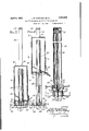
- Figure l is a side elevational view of the grain bin, showing ythe apparatus associated therewith'for raising and lowering the saine.
- Figure 2 is a perspective view of the binshowing the cover for the spout or opening therefor.
- Figure 8 is a vertical cross-sectional view through the bin showing the hydrauliclioist mounted therein for raising andI lowering the bin. This figure shows the bin in its lowered position whilebeing filled from the harvester machine.
- Figure 4 is a vertical cross-sectional view ⁇ 4 showing the same arrangement of the hydraulic hoisting mechanism and showiiigthe bin position readyv to be unloaded
- Figure 5 is -a vertical Vcross-sectional view of they hoisting ymechanism showing the construction ⁇ and arrangement of the same.
- the wall .6 is provided with a hinged gate l() for covering the opening ll of the bin.v
- the gate 10 is provided with" transverse ⁇ strips 412 adapted to seal ⁇ the gate lO against the side wall'6 of ⁇ the auxiliaryjbin: Similar strips 13 aresecured to the side wall 6 of the-bin for further sealing the opening l1 when the gate 10 is closed.
- Thefbinis also provided with side walls 14: bracedl by angle-irons l5 secured to the vertical edges of theside walls 14, the front 6, and back wall ⁇ 7.
- An opening 16 may be formed in the top wall 8 ot the bin for tilling-purposes,'such as Ythe grain spout from the harvester machine.
- the bin is provided with vertical guide meinbers 17 secured to the side wallslt for guiding the same in a vertical frame composed of vertical side bars 18 Connected by a top bar 19 extending transversely of the vertical bars 18.
- the lowermost ends of the vert-ical bars 1S are secured to a frame structure including side bars 2O which may be connected to the side framework of the harvester machine and the framework also includes transverse bars 21 having their ends connected to the bars 2O and also bars 22 which also have their ends connected to the bars and which extend outwardly from the framework 20.
- the lowermost ends of the vertical guide bars 18 are secured to the frame bars 2O by plates 23 or the like.
- the vertical guide bars 18 are braced by brace bars Q4 having their lower ends connected as at to the transverse bars 22 and their upper ends connected as at 26 to the vertical guide bars 18.
- the framework 20 including the transverse bars 21 and Q2 may be braced against strains by truss bars 27 having their ends 28 secured to the frame bars Q0.
- the hoisting apparatus includes a dash pot structure comprising a. cylinder 30 secured to the lower wall 9 of the bin by bolts or the like and projecting inwardly and upwardly in respect thereto.
- a piston 31 is reciprocably mounted in the cylinder 3() and is provided with hollow connect-ing rod 32 which passes through a guide bearing 33 which is secured by bolts 34 to the bottom wall 9 of the bin.
- the cylinder 30 is also secured to the bottom of the bin 9 by the bolts 34. Breather holes 35 are placed around guide bearing 3S.
- the conA ect-ing rod 32 is anged as at 36 and is secured to the transverse bars Q2 by fastening members 37.
- Mechanism for forcing fluid under pressure to the cylinder ⁇ 30 and it includes a pump 40 connected to a reservoir 41 by a pipe 42.
- a pipe 43 connects the T-joint 44 of the pump 40.
- a pipe 45 connects the reservoir 41 to the connecting rod 32 as at 46.
- Valves 47 and 48 are connected in the pipes 43 and 45 for controlling the fluid under pressure to the dash pot structure.
- the shaft 49 is connected to the harvester motor and is connected by a positive clutch 50 to the pump 40 through the medium of the bevel gear 51 and the pump gear 52.
- a false bottom 55 may be provided in the auxiliary bin an e it may be presented in such a manner as to allow its lower end to be in close relation to the opening 11 of the bin.
- the fluid pressure apparatus including the tank 41 and pump 40 may be supported by the extensions 22 of the transverse bars Q2 or the apparatus may be installed on a point on a harvester best situated for the power supply and for convenience of operation.
- the bm 6 may be filled from the harvester conveyor through the opening in the top thereof. After the bin has been loaded with grain, it is then raised vertically by the fluid pressure apparatus 40 and 41 through the medium of the dash pot structure 30 and is raised in such a manner as to bring the opening 11 of the bin 6 above the top of a truck or a wagon for unloading the bin 6 and the c0ntents thereof into said truck or wagon.
- lVhat we claim is 1.
- a harvesting machine a grain bin adapted to be vertically reciprocated, carried by the side of the harvesting machine, guide bars supported by the side of the harvesting machine for guiding the bin during its up and down movement, fluid pressure hoisting apparatus mounted inside of the bin and means for forcing Huid under pressure to the hoisting apparatus for effect ing up and down movement of the grain bin.
- a grain harvesting machine a grain bin, adapted to be vertically movably attached low down to the side of the harvesting machine, said grain bin having a greater height than thickness, said grain bin also having openings for the inlet and outlet of the grain, a fluid operated hoisting device mounted within the grain bin, and fluid pressure operating means mounted on the grain harvesting machine for forcing fluid under pressure for raising the grain bin while being unloaded.
Landscapes
- Life Sciences & Earth Sciences (AREA)
- Environmental Sciences (AREA)
- Harvesting Machines For Root Crops (AREA)
Description
April 5, 1932.. J. w. HoEFLlNG E1' AL GRAVITY DISCHARGE GRAIN BIN FOR"HARVESTERS 2 Sheets-Sheet 1 .Filed 0st. 24, 1928 J6? mmf.
April 5, 1932.
` J. W. HOEFLING ET AL Filed-Oct. 24, 1928 2 Sheets-Sheet 2 llwn 3o ez i f 3 g f 6 l l 3 .V35
ff/E- 34 \.T i a i Q l i v a l i 67|\n /4 v/72 zo zz, i /j f/ 1,-:6622 4m 3937 2/ z/ f. 1f zo T1G .5
Zz M @ad ATToRN v IN V EN TOR UNITED: STATE. s:
j igsszeaaf JOHN W. HOEFLING ANI) IPHELIPZMHOEFLINGQOF CHICO, CALIFORNA., ASSIGNORS T0 HEFLING- BROS'. INC., OF CHICO, CALIFORNIA, A CORPORATION 0E .CALIFORNIA l GRAVITY DISCHARGE einem4 Brit ron HARVESTERS Appiicauon filed october 24, icas. ,serial No. 314,825.
This invention relates to auxiliary bins for harvesting machines, particularly the type employed in present dayharvesting apparatus of the conventional form.
The primary object of 'this invention is to provide a device ot the above mentioned character, which may be associated with aV conventional form of harvesting machine, without necessitating changes in the structure or mechanical details of the same.
A further object of this invention is to provide a Vstorage bin of a shape which vwill n not cause Vdistortion to the `frame of the harvesting machine due to twisting and yswaying caused by traveling over unevenand irregular ground. x
A still further object of this invention is to provide a storage bin of the above mentioned character, adapted to hey easily raised or lowered for loading and l,unloading purposes. The raising and lowering of the bin may be accomplished by hoisting mechanism associated therewith.
It has heretofore beencominon practice to provide a harvesting machine with an attachment similar to a trailer, but having only one wheel on one side thereof, while the other side of the wagonl is' supported bythe harvester `frame. Such'y constructions are usually mounted relatively high on the harvester creating a high center of gravity particularly when loaded.` It will readily he seen that the height of this kind of attachment with" load will cause the body vtrame of the harvesterv and its machinery to be impaired by swaying and rocking.
The above practice is objectionable becausev the center of gravity is so high that the sway- -ing of the harvesterframe caused by such and without having an attachment travelino` over uneven and irr regular ground, cannotnbe prevented and the results are very serious.V f
The above diiii'cultiesV and disadvantages are overcome by providing a relatively narrow bin placed low down and close in on-the sidey of a harvester machine and .supported entirely on the latter vso thatV the same may pass through narrow gatesk without difficulty to be removed from the harvester machine and so'that the center of gravity of the bin is carried at as low a level as possible. When it is desired to unload the auxiliary bin the same may be quickly raised suiiciently high so that the contentsr thereof f may flow freely by gravity into the trucker wagon for haulingfrom the field.
Other objects and advantagesof the invention will become apparent during the course of the following description formingV a part of this specification and in which Figure l is a side elevational view of the grain bin, showing ythe apparatus associated therewith'for raising and lowering the saine.
Figure 2 is a perspective view of the binshowing the cover for the spout or opening therefor.
Figure 8 is a vertical cross-sectional view through the bin showing the hydrauliclioist mounted therein for raising andI lowering the bin. This figure shows the bin in its lowered position whilebeing filled from the harvester machine.
Figure 4: is a vertical cross-sectional view`4 showing the same arrangement of the hydraulic hoisting mechanism and showiiigthe bin position readyv to be unloaded,` and Figure 5 is -a vertical Vcross-sectional view of they hoisting ymechanism showing the construction `and arrangement of the same.
For the purpose of illustration, attention is rst directed to Figure 1,whereinfis shown the auxiliary bin having a Jfront wall 6, black wall 7,1' a top 8, `'and a bottom 9. The front.
wall .6 is provided with a hinged gate l() for covering the opening ll of the bin.v The gate 10 is provided with" transverse `strips 412 adapted to seal `the gate lO against the side wall'6 of `the auxiliaryjbin: Similar strips 13 aresecured to the side wall 6 of the-bin for further sealing the opening l1 when the gate 10 is closed.
Thefbinis also provided with side walls 14: bracedl by angle-irons l5 secured to the vertical edges of theside walls 14, the front 6, and back wall`7.
An opening 16 may be formed in the top wall 8 ot the bin for tilling-purposes,'such as Ythe grain spout from the harvester machine.
The bin is provided with vertical guide meinbers 17 secured to the side wallslt for guiding the same in a vertical frame composed of vertical side bars 18 Connected by a top bar 19 extending transversely of the vertical bars 18. The lowermost ends of the vert-ical bars 1S are secured to a frame structure including side bars 2O which may be connected to the side framework of the harvester machine and the framework also includes transverse bars 21 having their ends connected to the bars 2O and also bars 22 which also have their ends connected to the bars and which extend outwardly from the framework 20. The lowermost ends of the vertical guide bars 18 are secured to the frame bars 2O by plates 23 or the like. The vertical guide bars 18 are braced by brace bars Q4 having their lower ends connected as at to the transverse bars 22 and their upper ends connected as at 26 to the vertical guide bars 18.
The framework 20 including the transverse bars 21 and Q2 may be braced against strains by truss bars 27 having their ends 28 secured to the frame bars Q0.
The hoisting apparatus includes a dash pot structure comprising a. cylinder 30 secured to the lower wall 9 of the bin by bolts or the like and projecting inwardly and upwardly in respect thereto. A piston 31 is reciprocably mounted in the cylinder 3() and is provided with hollow connect-ing rod 32 which passes through a guide bearing 33 which is secured by bolts 34 to the bottom wall 9 of the bin. The cylinder 30 is also secured to the bottom of the bin 9 by the bolts 34. Breather holes 35 are placed around guide bearing 3S. The conA ect-ing rod 32 is anged as at 36 and is secured to the transverse bars Q2 by fastening members 37.
Mechanism is provided for forcing fluid under pressure to the cylinder` 30 and it includes a pump 40 connected to a reservoir 41 by a pipe 42. A pipe 43 connects the T-joint 44 of the pump 40. A pipe 45 connects the reservoir 41 to the connecting rod 32 as at 46. Valves 47 and 48 are connected in the pipes 43 and 45 for controlling the fluid under pressure to the dash pot structure.
The shaft 49 is connected to the harvester motor and is connected by a positive clutch 50 to the pump 40 through the medium of the bevel gear 51 and the pump gear 52.
A false bottom 55 may be provided in the auxiliary bin an e it may be presented in such a manner as to allow its lower end to be in close relation to the opening 11 of the bin.
The fluid pressure apparatus including the tank 41 and pump 40 may be supported by the extensions 22 of the transverse bars Q2 or the apparatus may be installed on a point on a harvester best situated for the power supply and for convenience of operation.
For a consideration of the operation of the device it will at this time be stated that the bm 6 may be filled from the harvester conveyor through the opening in the top thereof. After the bin has been loaded with grain, it is then raised vertically by the fluid pressure apparatus 40 and 41 through the medium of the dash pot structure 30 and is raised in such a manner as to bring the opening 11 of the bin 6 above the top of a truck or a wagon for unloading the bin 6 and the c0ntents thereof into said truck or wagon.
It is to be understood that the illustrations shown in the drawings are merely for the pur pose of setting forth the jist of the invention and that the operation of the bin in respect to the raising and lowering may be accomplished by other hoisting means common to the art, and it is also to be understood that various changes and arrangement of the parts may be resorted to without departing from the spirit of the invention or the scope of the subjoined claims.
lVhat we claim is 1. In combination, a harvesting machine, a grain bin adapted to be vertically reciprocated, carried by the side of the harvesting machine, guide bars supported by the side of the harvesting machine for guiding the bin during its up and down movement, fluid pressure hoisting apparatus mounted inside of the bin and means for forcing Huid under pressure to the hoisting apparatus for effect ing up and down movement of the grain bin.
In combination, a grain harvesting machine, a grain bin, adapted to be vertically movably attached low down to the side of the harvesting machine, said grain bin having a greater height than thickness, said grain bin also having openings for the inlet and outlet of the grain, a fluid operated hoisting device mounted within the grain bin, and fluid pressure operating means mounted on the grain harvesting machine for forcing fluid under pressure for raising the grain bin while being unloaded.
In testimony whereof we affix our signatures.
JOHN W. HOEFLIN G. PHILIP M. HOEFLING.
Priority Applications (1)
| Application Number | Priority Date | Filing Date | Title |
|---|---|---|---|
| US314825A US1852969A (en) | 1928-10-24 | 1928-10-24 | Gravity discharge grain bin for harvesters |
Applications Claiming Priority (1)
| Application Number | Priority Date | Filing Date | Title |
|---|---|---|---|
| US314825A US1852969A (en) | 1928-10-24 | 1928-10-24 | Gravity discharge grain bin for harvesters |
Publications (1)
| Publication Number | Publication Date |
|---|---|
| US1852969A true US1852969A (en) | 1932-04-05 |
Family
ID=23221617
Family Applications (1)
| Application Number | Title | Priority Date | Filing Date |
|---|---|---|---|
| US314825A Expired - Lifetime US1852969A (en) | 1928-10-24 | 1928-10-24 | Gravity discharge grain bin for harvesters |
Country Status (1)
| Country | Link |
|---|---|
| US (1) | US1852969A (en) |
-
1928
- 1928-10-24 US US314825A patent/US1852969A/en not_active Expired - Lifetime
Similar Documents
| Publication | Publication Date | Title |
|---|---|---|
| US3270921A (en) | Unloading system for bulk material bins | |
| US2498229A (en) | Portable service station mounted on a vehicle | |
| US2174956A (en) | Dumping truck | |
| US2268689A (en) | Tractor operated loader | |
| US2259558A (en) | Universally movable floor crane | |
| US2576881A (en) | Tail gate elevator loader for vehicles | |
| US1852969A (en) | Gravity discharge grain bin for harvesters | |
| US1350087A (en) | Truck-dumping mechanism | |
| US2834633A (en) | Operator's cab and grain tank arrangement for harvesters | |
| US2673436A (en) | Cotton picker | |
| US2185415A (en) | Machine for spreading pulverized materials | |
| US3084821A (en) | Cattle bunk feeder filler | |
| US2533362A (en) | Transit concrete mixer having adjustable discharge height | |
| US2210323A (en) | Conveying rig | |
| US1555760A (en) | Grain-bin attachment for harvester-thrashers | |
| US1751601A (en) | Grain tank for harvester thrashers | |
| US1444704A (en) | Vehicle-unloading apparatus | |
| US2681069A (en) | Apparatus for cleaning large articles | |
| US1271978A (en) | Hydraulic hoisting device. | |
| US3734563A (en) | Discharge mechanism for cotton harvester | |
| US2408401A (en) | Vehicle trailer | |
| US1402257A (en) | Freight-handling apparatus | |
| US1940043A (en) | Dumping truck | |
| KR0160756B1 (en) | Dump Truck Cargo Loading Device | |
| US1862159A (en) | Grain storage tank for threshers |