US1852949A - Pattern - Google Patents
Pattern Download PDFInfo
- Publication number
- US1852949A US1852949A US552222A US55222231A US1852949A US 1852949 A US1852949 A US 1852949A US 552222 A US552222 A US 552222A US 55222231 A US55222231 A US 55222231A US 1852949 A US1852949 A US 1852949A
- Authority
- US
- United States
- Prior art keywords
- pattern
- moulds
- blades
- mould
- axis
- Prior art date
- Legal status (The legal status is an assumption and is not a legal conclusion. Google has not performed a legal analysis and makes no representation as to the accuracy of the status listed.)
- Expired - Lifetime
Links
- 238000000465 moulding Methods 0.000 description 4
- 238000005266 casting Methods 0.000 description 1
Images

Classifications
-
- B—PERFORMING OPERATIONS; TRANSPORTING
- B22—CASTING; POWDER METALLURGY
- B22C—FOUNDRY MOULDING
- B22C7/00—Patterns; Manufacture thereof so far as not provided for in other classes
-
- Y—GENERAL TAGGING OF NEW TECHNOLOGICAL DEVELOPMENTS; GENERAL TAGGING OF CROSS-SECTIONAL TECHNOLOGIES SPANNING OVER SEVERAL SECTIONS OF THE IPC; TECHNICAL SUBJECTS COVERED BY FORMER USPC CROSS-REFERENCE ART COLLECTIONS [XRACs] AND DIGESTS
- Y10—TECHNICAL SUBJECTS COVERED BY FORMER USPC
- Y10T—TECHNICAL SUBJECTS COVERED BY FORMER US CLASSIFICATION
- Y10T29/00—Metal working
- Y10T29/49—Method of mechanical manufacture
- Y10T29/49316—Impeller making
- Y10T29/4932—Turbomachine making
- Y10T29/49325—Shaping integrally bladed rotor
Definitions
- This invention relates to the mouldingof a fan rotor havingoverlappingblades .and more particularly to a fan in which the width and geometrical pitch of the pressure side of the blades gradually increase towards the hub in such a way that the width and geometrical pitchiare at their maximum for the cross-section of theblade lying on the hub itself.
- the pattern is split into two parts at right angles to its axis one sin 'e castin bein obtained from the four moulds.
- a pattern for moulding a rotor having overlapping, blades comprising a plurality of sections, said pattern beingv divided in planes at right angles to its axis to facilitate removal thereof from a mould.
- the pat tern is split into three angles to its axis, one obtained.
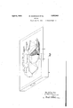
- Fig. 1 shows in sectional elevation the ap-' plication of the invention to the case when four moulds are used
- Fig. 2 shows a plan view of the moulding means illustrated in Fig. l with the upper mould removed
- Fig. 3 is an isometric view'ofthe bottom mould with the lower part of the pattern in position.
- a, b, a and d are the four moulds which are superposed on one another.
- the pattern is split into two parts 6 and fat right angles to its axis, 9 and h beingthe portions of the blades forming part of the respective pator four parts at right single casting beingv
Landscapes
- Engineering & Computer Science (AREA)
- Mechanical Engineering (AREA)
- Structures Of Non-Positive Displacement Pumps (AREA)
Description
April 1932- M. ADAMCIKAS ET AL 1,852,949
PATTERN Filed July 21, 1951 2 Sheets-Sheet 1 April 'M.'ADAMCIKAS ET AL 1,352,949
- PATTERN Filled July 21, 1931 2 Sheets-Sheet 2 Fig.3.
mew-mics Patented Apr. 5,119.32,
MYKAS ADAMGIKAS AND GIUSEPPE MASSERA,-OF .ALZDWYCH, LONDON, ENGLAND PATTERN Application filed. JuIy 21, 1931, SerialNo. 552,222,.and in Great Britain :MarchiS, 1930.
This invention relates to the mouldingof a fan rotor havingoverlappingblades .and more particularly to a fan in which the width and geometrical pitch of the pressure side of the blades gradually increase towards the hub in such a way that the width and geometrical pitchiare at their maximum for the cross-section of theblade lying on the hub itself. i
The moulding of a fan rotor having such blades causes great difficulties when the, blades overlap one another at the hub because of the twist of the blades and because of thecsand which comes to lie between the overlapping parts, and the object of the presprovide a moulding meth-,
ent invention is to 0d which will overcome this difliculty;
According to the present invention use is made instead of two moulds, of four or more planes at right angles to the axis of the rotor, fourv moulds being preferably used in the case of a blade overlapping at the hub up to and six or eight moulds when the overlappingis greater than 50%.
When four mouldsare used the pattern is split into two parts at right angles to its axis one sin 'e castin bein obtained from the four moulds.
vmoved downwardly and leaves a When this has been done the upper part 7 of the pattern is lifted upwardly, the lower' half 6 remaining in the sections a: and b of the mould. The mould section a is then clear pasthe lower mould secsage permitting the removal of section e of the pattern from the tion Z2.
What we claim is A pattern for moulding a rotor having overlapping, blades, comprising a plurality of sections, said pattern beingv divided in planes at right angles to its axis to facilitate removal thereof from a mould.
Intestimony whereof we have signed our names to this specification.
MYKAS ADAMOIKAS. GIUSEPPE MASSERA.
In the case of six or eight moulds, the pat tern is split into three angles to its axis, one obtained.
Referring to the accompanying drawings, which illustrate the invention by way of example,
Fig. 1 shows in sectional elevation the ap-' plication of the invention to the case when four moulds are used,
Fig. 2showing a plan view of the moulding means illustrated in Fig. l with the upper mould removed, while- Fig. 3 is an isometric view'ofthe bottom mould with the lower part of the pattern in position.
a, b, a and d are the four moulds which are superposed on one another. The pattern is split into two parts 6 and fat right angles to its axis, 9 and h beingthe portions of the blades forming part of the respective pator four parts at right single casting beingv
Applications Claiming Priority (1)
| Application Number | Priority Date | Filing Date | Title |
|---|---|---|---|
| GB1852949X | 1930-03-08 |
Publications (1)
| Publication Number | Publication Date |
|---|---|
| US1852949A true US1852949A (en) | 1932-04-05 |
Family
ID=10892003
Family Applications (1)
| Application Number | Title | Priority Date | Filing Date |
|---|---|---|---|
| US552222A Expired - Lifetime US1852949A (en) | 1930-03-08 | 1931-07-21 | Pattern |
Country Status (1)
| Country | Link |
|---|---|
| US (1) | US1852949A (en) |
-
1931
- 1931-07-21 US US552222A patent/US1852949A/en not_active Expired - Lifetime
Similar Documents
| Publication | Publication Date | Title |
|---|---|---|
| US1576019A (en) | Molding apparatus | |
| US1512484A (en) | Rotary-cutter knife | |
| US1852949A (en) | Pattern | |
| US2197212A (en) | Mold form | |
| US1932278A (en) | Method of manufacturing nozzle diaphragms and the like | |
| US2887744A (en) | Pattern for impeller core | |
| US2160467A (en) | Propeller | |
| US1783285A (en) | Mold | |
| US1686069A (en) | Propeller | |
| US2007572A (en) | Method of making ice cream and similar blocks having completely enclosed cores | |
| US1782088A (en) | Baking and molding device | |
| US1304102A (en) | routledge | |
| FR836571A (en) | Impeller for centrifugal cream separators and other similar machines | |
| US1784346A (en) | Cooling means for castings | |
| TAKAHASHI et al. | Natural crossing in Setaria italica (Beauv.) | |
| US1406365A (en) | Propeller and method of making the same | |
| CH238005A (en) | Process for the production of a blade for turbomachinery and the blade produced according to the process. | |
| US1175555A (en) | Art of casting metal. | |
| US1010337A (en) | Screw-propeller for flying-machines. | |
| US1432666A (en) | Core-box plate | |
| US1858124A (en) | Ice cube tray | |
| US1543701A (en) | Mold for propellers | |
| DE494348C (en) | Labyrinth stuffing box | |
| US1000528A (en) | Airship-propeller. | |
| US1015197A (en) | Flying-machine propeller. |