US1852948A - Golf instruction course - Google Patents
Golf instruction course Download PDFInfo
- Publication number
- US1852948A US1852948A US487034A US48703430A US1852948A US 1852948 A US1852948 A US 1852948A US 487034 A US487034 A US 487034A US 48703430 A US48703430 A US 48703430A US 1852948 A US1852948 A US 1852948A
- Authority
- US
- United States
- Prior art keywords
- ball
- course
- shutters
- shutter
- golf
- Prior art date
- Legal status (The legal status is an assumption and is not a legal conclusion. Google has not performed a legal analysis and makes no representation as to the accuracy of the status listed.)
- Expired - Lifetime
Links
Images

Classifications
-
- A—HUMAN NECESSITIES
- A63—SPORTS; GAMES; AMUSEMENTS
- A63B—APPARATUS FOR PHYSICAL TRAINING, GYMNASTICS, SWIMMING, CLIMBING, OR FENCING; BALL GAMES; TRAINING EQUIPMENT
- A63B24/00—Electric or electronic controls for exercising apparatus of preceding groups; Controlling or monitoring of exercises, sportive games, training or athletic performances
- A63B24/0021—Tracking a path or terminating locations
-
- A—HUMAN NECESSITIES
- A63—SPORTS; GAMES; AMUSEMENTS
- A63B—APPARATUS FOR PHYSICAL TRAINING, GYMNASTICS, SWIMMING, CLIMBING, OR FENCING; BALL GAMES; TRAINING EQUIPMENT
- A63B69/00—Training appliances or apparatus for special sports
- A63B69/36—Training appliances or apparatus for special sports for golf
- A63B69/3658—Means associated with the ball for indicating or measuring, e.g. speed, direction
-
- A—HUMAN NECESSITIES
- A63—SPORTS; GAMES; AMUSEMENTS
- A63B—APPARATUS FOR PHYSICAL TRAINING, GYMNASTICS, SWIMMING, CLIMBING, OR FENCING; BALL GAMES; TRAINING EQUIPMENT
- A63B24/00—Electric or electronic controls for exercising apparatus of preceding groups; Controlling or monitoring of exercises, sportive games, training or athletic performances
- A63B24/0021—Tracking a path or terminating locations
- A63B2024/0037—Tracking a path or terminating locations on a target surface or at impact on the ground
- A63B2024/004—Multiple detectors or sensors each defining a different zone
-
- A—HUMAN NECESSITIES
- A63—SPORTS; GAMES; AMUSEMENTS
- A63B—APPARATUS FOR PHYSICAL TRAINING, GYMNASTICS, SWIMMING, CLIMBING, OR FENCING; BALL GAMES; TRAINING EQUIPMENT
- A63B24/00—Electric or electronic controls for exercising apparatus of preceding groups; Controlling or monitoring of exercises, sportive games, training or athletic performances
- A63B24/0021—Tracking a path or terminating locations
- A63B2024/0037—Tracking a path or terminating locations on a target surface or at impact on the ground
- A63B2024/0046—Mechanical means for locating the point of impact or entry
-
- A—HUMAN NECESSITIES
- A63—SPORTS; GAMES; AMUSEMENTS
- A63B—APPARATUS FOR PHYSICAL TRAINING, GYMNASTICS, SWIMMING, CLIMBING, OR FENCING; BALL GAMES; TRAINING EQUIPMENT
- A63B2220/00—Measuring of physical parameters relating to sporting activity
- A63B2220/10—Positions
- A63B2220/16—Angular positions
-
- A—HUMAN NECESSITIES
- A63—SPORTS; GAMES; AMUSEMENTS
- A63B—APPARATUS FOR PHYSICAL TRAINING, GYMNASTICS, SWIMMING, CLIMBING, OR FENCING; BALL GAMES; TRAINING EQUIPMENT
- A63B2220/00—Measuring of physical parameters relating to sporting activity
- A63B2220/20—Distances or displacements
- A63B2220/24—Angular displacement
-
- A—HUMAN NECESSITIES
- A63—SPORTS; GAMES; AMUSEMENTS
- A63B—APPARATUS FOR PHYSICAL TRAINING, GYMNASTICS, SWIMMING, CLIMBING, OR FENCING; BALL GAMES; TRAINING EQUIPMENT
- A63B2220/00—Measuring of physical parameters relating to sporting activity
- A63B2220/50—Force related parameters
- A63B2220/51—Force
- A63B2220/52—Weight, e.g. weight distribution
-
- A—HUMAN NECESSITIES
- A63—SPORTS; GAMES; AMUSEMENTS
- A63B—APPARATUS FOR PHYSICAL TRAINING, GYMNASTICS, SWIMMING, CLIMBING, OR FENCING; BALL GAMES; TRAINING EQUIPMENT
- A63B2220/00—Measuring of physical parameters relating to sporting activity
- A63B2220/80—Special sensors, transducers or devices therefor
- A63B2220/801—Contact switches
-
- A—HUMAN NECESSITIES
- A63—SPORTS; GAMES; AMUSEMENTS
- A63B—APPARATUS FOR PHYSICAL TRAINING, GYMNASTICS, SWIMMING, CLIMBING, OR FENCING; BALL GAMES; TRAINING EQUIPMENT
- A63B69/00—Training appliances or apparatus for special sports
- A63B69/36—Training appliances or apparatus for special sports for golf
- A63B69/3691—Golf practising terrains
- A63B69/3694—Golf practising terrains for driving only
Definitions
- This invention relates to an improved golf instruction course, the object being to provide a construction wherein paintings and other helps are used to indicate the distance between the teeing oil' place and the putting green.
- Another object of the invention is to provide an improved instruction course wherein part of the course is an actual distance and w part a theoretical distance, the theoretical distance beingV painted or otherwise decorated to simulate the true distance.
- a further object of the invention is to provide a golf instruction course wherein there is provided means presenting a golf instruction course structure including a theoretical putting green and mechanical means arranged adjacent the putting green adapted to be operated by a blow Jfrom a ball hitting 2@ the putting green, said mechanical means acting to indicate the position and pressure of the striking ball.
- An additional object is to provide a golf instruction course wherein a painted canvas member is provided on which the putting green and other members are indicated and against which the ball is adaptedto be driven, the canvas coactive with mechanically actuated members 4for turning on and ott current to a signal light or other signal device.
- Figure 2 is a sectional view through Figure l approximately on the line 2 2;
- Figure 3 is an enlarged fragmentary sectional view showing ball operated shutters and switch mechanism actuated thereby;
- Figure 4 is a rear elevation of the structure shown in Figure
- Figure 5 is an enlarged fragmentary sectional view showing the mercury switch tube and associated parts illustrated in Figure 3;
- Figure 6 shows the same structure as shown in Figure 5 but in an operated position whereby the circuit is closed;
- Figure 7 is a view similar to Figure 6 but vcertain mechanism hereinafter showing the tube back in its original position with the mercury partially returned to its original position.
- Flgure'S is a sectional view through Figure 5 on the line 8,-8; 5r.
- Figure 9 is an enlarged rear view of th shutter mechanism illustrated on the left in Figure 2, the same being shown associated with the front View of the indicating panels or indicators shown at the right in Figure 2.
- 1 indicates 'a wall which may encircle all four sides of a spot to be enclosed, the same being made of canvas or other material, as desired. If preferred, only three ci: walls may be provided as shown in Figure I wlth the top eliminated, but usually the arrangement is as-shown in ' Figure 2 where all four walls are used and also a top 2, said top having a rear section 3 and a front section 7L 4 between which an electric lamp or other illuminating device 5 is placed whereby ample light is thrown on the fairway, putting greens and other parts of the course.
- f an electric lamp or other illuminating device 5
- the rear wall l should be made from canvas because it is adapted to be hit by a ball 6 and depressed, as shown in dotted lines in Fig. 3, whereby the i force of the ball may cause one of the shutters 7 to swing downwardly and thereb operate ully described.
- the ball 6 strikes the putting green 8 it will operate either of the two upper shutters 7, but if the ball strikes a little lower it will operate one of the lower shutters, provided the force is sufficient to perform the desired operation.
- each section is provided with a tee 18 which may or may not be used, as desired.
- the ball is placed at or adjacent the tee 18, and if it is desired to drive on the putting green 8 a proper drive is made.
- a person desires to practice putting he may place the ball anywhere near the tee 18 and drive the ball towards the hole 19. This is an actual distance and not a theoretical. distance, such distance being usually around eight feet although it may be made more or less.
- the ball will ydrop down into space 2O and roll down the inclined member 21 and eventually out through the opening 22, whereby the ball is returned to the player.
- Members 23 and 25 may be made of any desired material as, for instance, a strong grade of wire mesh covered with canvas, or other material, painted and otherwise decorated to give the appearance of a fairway or other part of a golf course.
- trees 27 are provided and also an imitation hedge 28.
- the trees 27 and also the hedge 28 are so proportioned as to give the impression of distance and also an impression of merging into the scenery 29 paints ed on the rear wall 1.
- a picture is painted on the rear wall and alsovon the side walls, the rear wall showing the different parts of a golf course including putting green 8 and also other putting greens 30, 31 and 32, said other putting greens-being positioned so as to appear to be at different. distances from the various sections 13 to 16, inclusive.
- the green 31 is indicated as being further off than any of the other greens and, therefore, any one playing on section 15 will seemingly drive a greater distance.
- the shutter mechanism back of putting green 31 may be adjusted to require heavier blows of the ball to cause the actuation thereof.
- Spring 33 bears'against a plate or bar 40, While a nut 41 locked in place by set screw 42 limits the return movement of the rod 37 so that the shutter 7 will swing downwardly at a predetermined angle against the tension of spring 33.
- Rod 37 at the end opposite shutter 7 is bifurcated and through bifurcations the arms 43 extend, said arms havin a slot 44 for accommodating the pin 45 carried at the end of rod 37.
- Rod 43 is pivotally mounted at 46 on a fixed post 47, while the upper end is pivotally mounted at 48 to a frame 49 holding the mercury switch 50.
- a fixed post 51 is secured in any desired position to the plate or bar and carries a pin 52 which pivotally connects the link 53 with post 51.
- link 53 is connected at 54 to the frame 49, whereby whenever rod 37 is forced outwardly to the dotted position shown in Figure 3, link 53 as well as link 43 will move to the dotted position shown in Figure 3 and thereb cause the mercury 54 to be projected to tie opposite end of the mercury switch or into the chamber 55 ( Figure 6).
- the mercury switch 50 moves quickly over to the dotted position shown in Figure 3 and then quickly back. If it were not for the slow return of the mercury to its original position the closing of the circuit would be only momentary, but by reason of the structure shown in Figures 5 to 8, inclusive, the mercury is returned slowly and consequently the lamp 12 is supplied with current for an appreciable time as, for instance, six or eight seconds. It will be understood that there is al mercury switch for each of the lamps 12.
- the mercury switch 50 is provided with a tubular casing 58 preferably of glass, said casing being divided by the base 59 of a funnel 60.
- the mercury will flow more or less slowly through opening 62 x and until it is practically all back in chamber 61 the circuit will remain closed, but as soon as the mercury moves out of contact with the terminals 56 and 57 the circuit will be automatically open.
- the size of the opening 62 the time in which the lamps 12 remain lighted may be varied. Also, by varying the amount of mercury used the same result may be secured within certain limits.
- the device may be made any desired size, but the preferred form has been produced wherein the distance from the hole 19 to the tee 18 is eight feet more or less, and the distance between the tee 18 to the putting green 8 is approximately thirty-three feet. A greater or even less distance may be used and the parts arranged as disclosed. e
- the top 2 is not necessary and may be eliminated, but at night or at other times the sections 3 and l of top 2 may be used and when this is the case one or more illuminating members or lamps 5 are provided for lighting to a great extent the main part of the course. f desired, small lamps can be arranged near the various sections 18 to 16 inclusive, although the main illumination is for the fairway and other parts of the course including the various putting greens.
- a golf instruction course including means having depicted thereon a putting green against which a ball is adapted to be driven, said means including a flexible wall, a plurality of hingedly mounted shutters arranged back of said wall, certain of said shutters being adjacent said putting green i whereby when the ball strikes the putting green it will swingably move one of said shutters, electrically operated indicating means, and means including a mercury switch operated by the respective shutters for closing the circuit of said electrically operated means whereb when any of said shutters are struck with a all having sufficient forceto swingf abl move the shutter the indicator will flash a igit indicating the particular shutter struc 2.
- a golf instruction course including means having depicted thereon a putting green against which a ball is adapted to be driven, a plurality of shutters mounted behind said putting green, a plurality of shutters arranged belnnd and beneath said putting greenall of said shutters being arranged in a single vertical row, the top shutter of said row being shorter than the bottom shutter and the intermediate shutters gradually varying in length from the top to the bottom of said row, and independent means operated by each of said shutters for causing the actuation of an indicator near the spot from which the ball is driven.
- an indicator provided with panels having numbers indicating distances thereon, an independent electric lamp for illuminating each of said numbers, a circuit for each of said lamps, each of said circuits including a source of current, conducting wires, and a mercury switch, and
- a plurality of shutters adapted to move when a ball is driven against the same, a spring for resiliently holding the shutter in a given position, a mercury switch, means actuated by said shutter against the action of said spring for moving the mercury switch to a closed position, said spring acting to return said switch and shutter after each operation, and a signal member interposed in the circuit of said switch whereby when said switch has been moved to a closed position said signal member will be actuated.
- a golf instruction course including a platform on which a ball is adapted to be positioned, a plurality of members arranged in specified layers, said layers having depicted thereon the fairway of a golf course, each of said members being inclined upwardly away from one edge of said platform, the lowest of said members extending the furthest from said platform whereby 'when a ball strikes the same it will roll back to near the starting point, a flexible wall positioned with its lower edge adjacent the outer end of said lowest member, said wall being provided with scenery depicting the remaining part of the golf course including putting greens, and means arranged behind said wall adjacent each of said depicted putting greens for indicating when a ball strikes the depicted putting green or a point immediately therebelow.
- a olf instruction course includin a supporting platform from which a balFis adapted to be driven, said platform at one edge being formed wlth a hole whereby the platform may act as an actual size putting 6 green, means formed as an inclined fairway, said means having one end projectin below said platform while the other end is mclined u wardly, wherebya ball passing from the p atform and dropping on said means will lo roll downwardly beneath the platform, a representation of a portion of a golf course arranged beneath the first mentioned means and extending beneath said platform, the same being inclined so that a all dropping thereon will roll beneath said platform by gravity to a point adjacent one edge thereof and be thereby recovered, and a canvas wall having a picture painted thereon including part of the olf course includin puttin greens where y any one driving rom sai platform toward the putting green may see the result of his shot and may have the ball returned to a position near one edge of the platform.
Landscapes
- Health & Medical Sciences (AREA)
- General Health & Medical Sciences (AREA)
- Physical Education & Sports Medicine (AREA)
- Life Sciences & Earth Sciences (AREA)
- Biophysics (AREA)
- Audible And Visible Signals (AREA)
Description
April 5, 1932. L. R. WARREN E'rAL 1,35 2948 GOLF' INSTRUCTION COURSE I Filed Oct. '7. 1930 3 Sheets-Sheet 1 N D I ATTORNEYSv l.. R. WARREN E'r AL GOLF INSTRUCTION COURSE April 5, 1932.k
3 Sheets-Shet 2 Filed Oct. 7. 1950 INVENTORS Leon, RJlfrnen/ Y wlTNEssE ArroRNEYa April f5,` 1932. L. R. WARREN E'r AL 1,852,948
GOLF INS'IRUC'II0N COURSE Filed oct. v. 1930 s sheets-sheet 3 INVENTORS Leon R. warren WITNESSES Ji'arlg/ 6. GLlb ATTORNEYS Patented Apr.g 5, 1932 Uiu'rclaznv STATES- PATENT oFFIcE LEON' B.' yWARREN, 0F JACKSON HEIGHTS, AND' HARRY C. GILL, OF WHITESTONE LANDING, NEW YCBK GOLF INSTRUCTION COURSE Application led October 7, 1930. Serial No. 487,034.
This invention relates to an improved golf instruction course, the object being to provide a construction wherein paintings and other helps are used to indicate the distance between the teeing oil' place and the putting green.
Another object of the invention is to provide an improved instruction course wherein part of the course is an actual distance and w part a theoretical distance, the theoretical distance beingV painted or otherwise decorated to simulate the true distance.
A further object of the invention is to provide a golf instruction course wherein there is provided means presenting a golf instruction course structure including a theoretical putting green and mechanical means arranged adjacent the putting green adapted to be operated by a blow Jfrom a ball hitting 2@ the putting green, said mechanical means acting to indicate the position and pressure of the striking ball.
An additional object, more specifically, is to provide a golf instruction course wherein a painted canvas member is provided on which the putting green and other members are indicated and against which the ball is adaptedto be driven, the canvas coactive with mechanically actuated members 4for turning on and ott current to a signal light or other signal device.
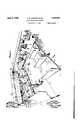
ln the accompanying drawings- Figure 1 is a perspective view with certain parts removed and other parts broken away,
the view representing an instruction course disclosing an embodiment of the invention;
Figure 2 is a sectional view through Figure l approximately on the line 2 2;
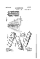
Figure 3 is an enlarged fragmentary sectional view showing ball operated shutters and switch mechanism actuated thereby;
Figure 4 is a rear elevation of the structure shown in Figure;
Figure 5 is an enlarged fragmentary sectional view showing the mercury switch tube and associated parts illustrated in Figure 3; Figure 6 shows the same structure as shown in Figure 5 but in an operated position whereby the circuit is closed;
Figure 7 is a view similar to Figure 6 but vcertain mechanism hereinafter showing the tube back in its original position with the mercury partially returned to its original position.
Flgure'S is a sectional view through Figure 5 on the line 8,-8; 5r.
Figure 9 is an enlarged rear view of th shutter mechanism ilustrated on the left in Figure 2, the same being shown associated with the front View of the indicating panels or indicators shown at the right in Figure 2. se
Referring to the accompanyingA drawings by numerals, 1 indicates 'a wall which may encircle all four sides of a spot to be enclosed, the same being made of canvas or other material, as desired. If preferred, only three ci: walls may be provided as shown in Figure I wlth the top eliminated, but usually the arrangement is as-shown in 'Figure 2 where all four walls are used and also a top 2, said top having a rear section 3 and a front section 7L 4 between which an electric lamp or other illuminating device 5 is placed whereby ample light is thrown on the fairway, putting greens and other parts of the course. f
In either arrangement of walls the rear wall l should be made from canvas because it is adapted to be hit by a ball 6 and depressed, as shown in dotted lines in Fig. 3, whereby the i force of the ball may cause one of the shutters 7 to swing downwardly and thereb operate ully described. As illustrated in Figure 2, if the ball 6 strikes the putting green 8 it will operate either of the two upper shutters 7, but if the ball strikes a little lower it will operate one of the lower shutters, provided the force is sufficient to perform the desired operation.
If the force of the ball is not suiiicient to depress or swing downwardly one of the shutters 7 or if the ball hits at one side of or above or below the shutter stand 9, no indication will occur in the indicator 10. However, if the top shutter 7 is stuck and properly operated the 250-yard panel l1 (Figure 9) 95 will be illuminated by reason of the fact that the circuit of lamp 12 will be closed. If any of the other shutters are struck with the proper force a corresponding action will take place and that particular panel in the indica- 100 tor will be illuminated. This illumination is only temporar as, for instance, approximately six secon s.
As illustrated, there are provided sections 13, 14, and 1G, said sections being divided b suitable walls 17 so that the respective players will not interfere with one another. Each section is provided with a tee 18 which may or may not be used, as desired. However, the ball is placed at or adjacent the tee 18, and if it is desired to drive on the putting green 8 a proper drive is made. However, if a person desires to practice putting he may place the ball anywhere near the tee 18 and drive the ball towards the hole 19. This is an actual distance and not a theoretical. distance, such distance being usually around eight feet although it may be made more or less. As soon as the ball enters the hole 19 it will ydrop down into space 2O and roll down the inclined member 21 and eventually out through the opening 22, whereby the ball is returned to the player.
Also, when driving the ball towards the putting green 8 sometimes it will drop on the fairway 23, and in a case of this kind the ball will automatically roll back through the opening 24 to the space 20, and finally out through the opening 22. When the ball strikes the putting green 8 or any part of the rear wall 1 it will fall down on the member 25 and roll down through opening 26 into space 20, and finally out through opening 22. In this way the ball is automatically returned after each drive of the player.
1n order to cause a person using section 15 to actually drive harder than a person using section 14 the shutter mechanism back of putting green 31 may be adjusted to require heavier blows of the ball to cause the actuation thereof.
With regard to actuating the Various shutters it will be seen that when a ball 6 -,trikes the wall 1 as indicated in dotted lines in Figure 3, the canvas will yield and the pressure or blow of the ball will cause the shutter 7 to swing inwardly against the action of the spring It will be noted that the shutter 7 is liingedly mounted at 34 on a suitable support 35 and that at point 36 the threaded rod 37 is pivotally connected with the shutter. A nut 38 is mounted on rod 37, said nut being capable of being adjusted to vary the tension of the spring 33, and when adjusted is locked against movement by set screw 39. Spring 33 bears'against a plate or bar 40, While a nut 41 locked in place by set screw 42 limits the return movement of the rod 37 so that the shutter 7 will swing downwardly at a predetermined angle against the tension of spring 33. Rod 37 at the end opposite shutter 7 is bifurcated and through bifurcations the arms 43 extend, said arms havin a slot 44 for accommodating the pin 45 carried at the end of rod 37. Rod 43 is pivotally mounted at 46 on a fixed post 47, while the upper end is pivotally mounted at 48 to a frame 49 holding the mercury switch 50. A fixed post 51 is secured in any desired position to the plate or bar and carries a pin 52 which pivotally connects the link 53 with post 51. At the upper end link 53 is connected at 54 to the frame 49, whereby whenever rod 37 is forced outwardly to the dotted position shown in Figure 3, link 53 as well as link 43 will move to the dotted position shown in Figure 3 and thereb cause the mercury 54 to be projected to tie opposite end of the mercury switch or into the chamber 55 (Figure 6). Y
W'hen thistakes place the terminals 5G and 57 are connected by the mercury, said terminals being the terminals of the wires leading to a suitable source of current and to the respective lamps 12. Therefore, whenever the mercury switch 50 is moved to the dotted position shown in Figure 3 or the position shown in Figure 6, the circuit will be closed and the desired lamp 12 lighted.
It will be understood that the mercury switch 50 moves quickly over to the dotted position shown in Figure 3 and then quickly back. If it were not for the slow return of the mercury to its original position the closing of the circuit would be only momentary, but by reason of the structure shown in Figures 5 to 8, inclusive, the mercury is returned slowly and consequently the lamp 12 is supplied with current for an appreciable time as, for instance, six or eight seconds. It will be understood that there is al mercury switch for each of the lamps 12.
As illustrated in these figures the mercury switch 50 is provided with a tubular casing 58 preferably of glass, said casing being divided by the base 59 of a funnel 60. By reason of thedividing of the casing compartvided in the base 59 so that when the switch" is moved back to its normal position, as shown in Figures 3 and 7, the mercury will flow more or less slowly through opening 62 x and until it is practically all back in chamber 61 the circuit will remain closed, but as soon as the mercury moves out of contact with the terminals 56 and 57 the circuit will be automatically open. By varying the size of the opening 62 the time in which the lamps 12 remain lighted may be varied. Also, by varying the amount of mercury used the same result may be secured within certain limits.
It will be evident that the device may be made any desired size, but the preferred form has been produced wherein the distance from the hole 19 to the tee 18 is eight feet more or less, and the distance between the tee 18 to the putting green 8 is approximately thirty-three feet. A greater or even less distance may be used and the parts arranged as disclosed. e
lVhen playing in the day time out-of-doors the top 2 is not necessary and may be eliminated, but at night or at other times the sections 3 and l of top 2 may be used and when this is the case one or more illuminating members or lamps 5 are provided for lighting to a great extent the main part of the course. f desired, small lamps can be arranged near the various sections 18 to 16 inclusive, although the main illumination is for the fairway and other parts of the course including the various putting greens.
It will be noted that by providing an actual distance from the tee to the hole 19 actual putting may take place, and by providing a theoretical distance from the tee to the putting green 8 and providing mea-nsl requiring a certain pressure on the stroke important results may be secured when using the device, which is intended both for pleasure and for instruction.
Ve claim- 1. A golf instruction course including means having depicted thereon a putting green against which a ball is adapted to be driven, said means including a flexible wall, a plurality of hingedly mounted shutters arranged back of said wall, certain of said shutters being adjacent said putting green i whereby when the ball strikes the putting green it will swingably move one of said shutters, electrically operated indicating means, and means including a mercury switch operated by the respective shutters for closing the circuit of said electrically operated means whereb when any of said shutters are struck with a all having sufficient forceto swingf abl move the shutter the indicator will flash a igit indicating the particular shutter struc 2. A golf instruction course including means having depicted thereon a putting green against which a ball is adapted to be driven, a plurality of shutters mounted behind said putting green, a plurality of shutters arranged belnnd and beneath said putting greenall of said shutters being arranged in a single vertical row, the top shutter of said row being shorter than the bottom shutter and the intermediate shutters gradually varying in length from the top to the bottom of said row, and independent means operated by each of said shutters for causing the actuation of an indicator near the spot from which the ball is driven.
3. In a golf instruction course an indicator provided with panels having numbers indicating distances thereon, an independent electric lamp for illuminating each of said numbers, a circuit for each of said lamps, each of said circuits including a source of current, conducting wires, and a mercury switch, and
`a swingable shutter connected with each of said mercury switches for actuating the switches and closing said circuits whenever a particular shutter has been swung a given distance by a blow from a ball driven against the same.
4. In a golf instruction course, a plurality of shutters adapted to move when a ball is driven against the same, a spring for resiliently holding the shutter in a given position, a mercury switch, means actuated by said shutter against the action of said spring for moving the mercury switch to a closed position, said spring acting to return said switch and shutter after each operation, and a signal member interposed in the circuit of said switch whereby when said switch has been moved to a closed position said signal member will be actuated.
5. A golf instruction course including a platform on which a ball is adapted to be positioned, a plurality of members arranged in specified layers, said layers having depicted thereon the fairway of a golf course, each of said members being inclined upwardly away from one edge of said platform, the lowest of said members extending the furthest from said platform whereby 'when a ball strikes the same it will roll back to near the starting point, a flexible wall positioned with its lower edge adjacent the outer end of said lowest member, said wall being provided with scenery depicting the remaining part of the golf course including putting greens, and means arranged behind said wall adjacent each of said depicted putting greens for indicating when a ball strikes the depicted putting green or a point immediately therebelow.
6. A olf instruction course includin a supporting platform from which a balFis adapted to be driven, said platform at one edge being formed wlth a hole whereby the platform may act as an actual size putting 6 green, means formed as an inclined fairway, said means having one end projectin below said platform while the other end is mclined u wardly, wherebya ball passing from the p atform and dropping on said means will lo roll downwardly beneath the platform, a representation of a portion of a golf course arranged beneath the first mentioned means and extending beneath said platform, the same being inclined so that a all dropping thereon will roll beneath said platform by gravity to a point adjacent one edge thereof and be thereby recovered, and a canvas wall having a picture painted thereon including part of the olf course includin puttin greens where y any one driving rom sai platform toward the putting green may see the result of his shot and may have the ball returned to a position near one edge of the platform.
LEON R. WARREN.
HARRY C. GILL.
Priority Applications (1)
| Application Number | Priority Date | Filing Date | Title |
|---|---|---|---|
| US487034A US1852948A (en) | 1930-10-07 | 1930-10-07 | Golf instruction course |
Applications Claiming Priority (1)
| Application Number | Priority Date | Filing Date | Title |
|---|---|---|---|
| US487034A US1852948A (en) | 1930-10-07 | 1930-10-07 | Golf instruction course |
Publications (1)
| Publication Number | Publication Date |
|---|---|
| US1852948A true US1852948A (en) | 1932-04-05 |
Family
ID=23934138
Family Applications (1)
| Application Number | Title | Priority Date | Filing Date |
|---|---|---|---|
| US487034A Expired - Lifetime US1852948A (en) | 1930-10-07 | 1930-10-07 | Golf instruction course |
Country Status (1)
| Country | Link |
|---|---|
| US (1) | US1852948A (en) |
Cited By (8)
| Publication number | Priority date | Publication date | Assignee | Title |
|---|---|---|---|---|
| US2789822A (en) * | 1955-02-07 | 1957-04-23 | Faizi Salih | Target with electrical indicator |
| US3334900A (en) * | 1964-07-15 | 1967-08-08 | Shaw Al | Interference eliminating wall member for bowling alleys |
| US3904209A (en) * | 1974-03-25 | 1975-09-09 | Clarence A Thomas | Compact golf course |
| WO1988004944A1 (en) * | 1986-12-24 | 1988-07-14 | Vernon Harold Newman | Arena and facility for the playing or practising of ball games |
| US5482269A (en) * | 1995-01-10 | 1996-01-09 | Scott; Ralph M. | Driving range tee area diving method |
| US5586942A (en) * | 1996-01-23 | 1996-12-24 | Wittek Golf Supply Co., Inc. | Tee divider for golf driving range |
| US5588652A (en) * | 1995-09-18 | 1996-12-31 | Lang; John | Golf range game |
| USD435279S (en) * | 2000-02-28 | 2000-12-19 | Ball-O-Matic, Inc. | Golf driving range tee divider |
-
1930
- 1930-10-07 US US487034A patent/US1852948A/en not_active Expired - Lifetime
Cited By (10)
| Publication number | Priority date | Publication date | Assignee | Title |
|---|---|---|---|---|
| US2789822A (en) * | 1955-02-07 | 1957-04-23 | Faizi Salih | Target with electrical indicator |
| US3334900A (en) * | 1964-07-15 | 1967-08-08 | Shaw Al | Interference eliminating wall member for bowling alleys |
| US3904209A (en) * | 1974-03-25 | 1975-09-09 | Clarence A Thomas | Compact golf course |
| WO1988004944A1 (en) * | 1986-12-24 | 1988-07-14 | Vernon Harold Newman | Arena and facility for the playing or practising of ball games |
| US4948141A (en) * | 1986-12-24 | 1990-08-14 | Newman Vernon H | Golf game facility |
| US5482269A (en) * | 1995-01-10 | 1996-01-09 | Scott; Ralph M. | Driving range tee area diving method |
| US5588652A (en) * | 1995-09-18 | 1996-12-31 | Lang; John | Golf range game |
| US5586942A (en) * | 1996-01-23 | 1996-12-24 | Wittek Golf Supply Co., Inc. | Tee divider for golf driving range |
| USRE37013E1 (en) | 1996-01-23 | 2001-01-09 | Wittek Golf Supply Co., Inc. | Tee divider for golf driving range |
| USD435279S (en) * | 2000-02-28 | 2000-12-19 | Ball-O-Matic, Inc. | Golf driving range tee divider |
Similar Documents
| Publication | Publication Date | Title |
|---|---|---|
| US4199141A (en) | Baseball pitching scoring apparatus | |
| US3380305A (en) | Baseball and baseball bat toy | |
| US1852948A (en) | Golf instruction course | |
| US2617653A (en) | Basketball game apparatus | |
| US3411788A (en) | Golf game apparatus with electrical scoring means | |
| US1799263A (en) | Golf-game apparatus | |
| US1733606A (en) | Game | |
| US1869642A (en) | Golf drive registering device | |
| US1952187A (en) | Game | |
| US1761317A (en) | Automatic golf link | |
| US1431695A (en) | Automatic bowling alley | |
| US4369971A (en) | Electronic bowling game | |
| US4265449A (en) | Simulated bowling game | |
| US2171295A (en) | Card and dice game | |
| US2776835A (en) | Racing game apparatus | |
| US3727740A (en) | Coin-operated trained animal amusement apparatus | |
| US3254433A (en) | Scoring device | |
| US3366387A (en) | Golf putting game apparatus for utilization by a plurality of players | |
| US1788336A (en) | Weight-operated switch | |
| US2317126A (en) | Game | |
| US2722421A (en) | Luminescent game target | |
| JPH08332256A (en) | Athletic competition performance method and apparatus | |
| US2107211A (en) | Game apparatus | |
| US1899860A (en) | Game apparatus | |
| US4089525A (en) | Pro-skill basketball game |