US1852945A - Rebound clamp - Google Patents
Rebound clamp Download PDFInfo
- Publication number
- US1852945A US1852945A US496488A US49648830A US1852945A US 1852945 A US1852945 A US 1852945A US 496488 A US496488 A US 496488A US 49648830 A US49648830 A US 49648830A US 1852945 A US1852945 A US 1852945A
- Authority
- US
- United States
- Prior art keywords
- clamp
- lever
- brake
- arm
- rebound
- Prior art date
- Legal status (The legal status is an assumption and is not a legal conclusion. Google has not performed a legal analysis and makes no representation as to the accuracy of the status listed.)
- Expired - Lifetime
Links
Images
Classifications
-
- F—MECHANICAL ENGINEERING; LIGHTING; HEATING; WEAPONS; BLASTING
- F16—ENGINEERING ELEMENTS AND UNITS; GENERAL MEASURES FOR PRODUCING AND MAINTAINING EFFECTIVE FUNCTIONING OF MACHINES OR INSTALLATIONS; THERMAL INSULATION IN GENERAL
- F16D—COUPLINGS FOR TRANSMITTING ROTATION; CLUTCHES; BRAKES
- F16D49/00—Brakes with a braking member co-operating with the periphery of a drum, wheel-rim, or the like
- F16D49/08—Brakes with a braking member co-operating with the periphery of a drum, wheel-rim, or the like shaped as an encircling band extending over approximately 360 degrees
-
- F—MECHANICAL ENGINEERING; LIGHTING; HEATING; WEAPONS; BLASTING
- F16—ENGINEERING ELEMENTS AND UNITS; GENERAL MEASURES FOR PRODUCING AND MAINTAINING EFFECTIVE FUNCTIONING OF MACHINES OR INSTALLATIONS; THERMAL INSULATION IN GENERAL
- F16D—COUPLINGS FOR TRANSMITTING ROTATION; CLUTCHES; BRAKES
- F16D59/00—Self-acting brakes, e.g. coming into operation at a predetermined speed
- F16D59/02—Self-acting brakes, e.g. coming into operation at a predetermined speed spring-loaded and adapted to be released by mechanical, fluid, or electromagnetic means
Definitions
- Thisxinvention relates to clamping; devices and has for its object the provision of a novel rebound clamp adapted particularly for use with a weighted lever arm, such as the actu 'atingflever for brake apparatus of the type disclosed inmy Patent No. 1,621A42, dated March 15, "1927.
- Such a leverfis 'gravitally operated to apply 'or' operate the brake apparatus which functions .to to the particular machine with'w'hich 'it';i 's"as socia ted.
- the lever has a natural and inherenttendency to rebound upon reachingthelower limit of its downwardmotion, thereby causmg undes rable lunstead application of the brake;-
- the undesirability, of this tendency to rebound is obvioudfthechief objection being that the machine'is'not stopped as quickly aswould otherwise be the case if the brake were unsteadily and continuously applied, The importance of stopping-the machine quickly,
- JA device provided in accordance with the invention prevents this inherent action of the lever by clamping-it firmly immediately upon its, reaching the lower limit of its Vm otion.
- Such a device may comprise a unitary clamp of simple construction, which may be pivotally mounted and adapted to be actuated by the lever in itsidownward motion.
- the simplicity of the device . is-acvery important feature of the invention;
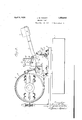
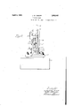
- the details of construction of the device .of the invention, as well as” its manner of operation. will be apparent from the following detailed description taken in connection with the accompanying drawings, in which Fig. 1 is a side elevation of the brake apparatus to which the device of the invention is .F'Q. 2'is an end the'apparatus of Fig.1; v '7 I have chosen to illustrate the invention elevation: of
- a power shaft 1 whichmay be the shaft of any ma- 5 chine with which the apparatus is associated.
- a brake drum 2 is mounted uponashaftxlyand has associated therewith a suitable brake band 3.
- i One end of the brake, band is fastened to pin 4:, which, in turn, is rigidly carriedby the walls of the supporting v66 device 5.
- the support5 comprises a pair, of parallel vertical walls, and is mounted upona base plate 6.
- the plate 6 may; in turn, be mounted upon a block 7?, which may be supported uponthe bed plate ofthemachine with which theapparatus is used.
- the other end of the brake band 3 is attached to' a suitable brake-actuatinglever 8 by 1 means of an adjustableblock'and bolt mechanism 9 of known design.
- the brake-actuating lever is pivotallysupported at one end upon'a pin 10, which maybe suitably journaled in the vertical walls of support 5.
- An adjustable'weight 11 is provided upon the other end of lever '8,'and it will be apparent that the purpose of such weightis to carry the lever downward to apply the brake band to the brake drum to stop rotation of shaft 1.
- a solenoid-operatin'g latch 12 may be provided.
- This latch and its associated structure forms no part of the present invention, but is disclosed and claimed in copending application, Ser. No. 496,489 filed Nov. 18, 1930JA's clearly set forth in that application, the latch is pivotally mounted upon support 5 and is connected to the armatureof a solenoid 13; which may also be carried by the support;
- solenoid13 is'normally energized and functions to maintain the latch 12 in operative position, as shown clearly in Fig. 1.
- the brake apparatus is rendered operative by deenergizing the solenoid, thereby permitting the latch to swing upon its pivot and to become disengaged from a roller 1& carried by lever 5 8. Weight 11 then forcibly carries the lever arm downward to apply the brake.
- a rebound clamp 15 which may be mounted upon an upstanding endwall 16 of support 5.
- This clamp preferably takes the form of a unitary U-shaped device having a pair of extending arms, 17 and 18.
- the recess of the clamp is dimensioned so that it will snugly receive lever 8.
- the clamp is pivotaly mounted at 19, and it will be apparent that this point is offset from the center of gravity of the device. Therefore, the clamp will have a tendency to rotate due to its own weight.
- this handle member may take the form of a threaded pin adapted to be screwed into a tapped opening in the clamp.
- the upper arm 18 of the clamp is preferably fornnd so as to be slightly hook shaped to insure positive gripping and holding of the blake-actuating lever.
- the brake apparains is in inoperative position, as shown in the figures of the drawings.
- the clamp is then disposed in the position shown clearly in Fig. 2.
- the lower arm 17 of the clamp lies directly in the path of the brake-actuating lever.
- the brake-actuating lever will now move forcibly downward and upon reaching the lower limit of its motion, it will strike the arm 17 of the clamp, thereby rotating the clamp counterclockwise.
- the upper arm 18 of the clamp will pass over the lever, and the device will thus grip the lever and prevent rebounding of the same.
- the brake apparatus may be reset by manually lifting the weighted lever arm when it is desired to start the machine again and to render the brake inoperative.
- the clamp may be moved clockwise to the position shown in Fig. 2, to thereby release the lever and allow the same to be raised.
Landscapes
- Engineering & Computer Science (AREA)
- General Engineering & Computer Science (AREA)
- Mechanical Engineering (AREA)
- Physics & Mathematics (AREA)
- Electromagnetism (AREA)
- Braking Arrangements (AREA)
Description
April J. w. THROPP 1,852,945
REBOUND CLAMP Filed Nov. 18, 1950 2 Sheets-Shet 1 April" 5, 1932. T PP 1,852,945
REBOUND CLAMP Filed Nov. 18, 1930 2 ShGets-Sheet 2 Patented I Apr, 5, .1932
, JOSEPH :W. THROPP, 0F TRENTON, NEW JERSEY I REBOUND CLAIVIP Applieation filed November 1s, 1930. Serial No; 496,488.
Thisxinvention relates to clamping; devices and has for its object the provision of a novel rebound clamp adapted particularly for use with a weighted lever arm, such as the actu 'atingflever for brake apparatus of the type disclosed inmy Patent No. 1,621A42, dated March 15, "1927. Such a leverfis 'gravitally operated to apply 'or' operate the brake apparatus, which functions .to to the particular machine with'w'hich 'it';i 's"as socia ted.- The lever has a natural and inherenttendency to rebound upon reachingthelower limit of its downwardmotion, thereby causmg undes rable lunstead application of the brake;- The undesirability, of this tendency to rebound is obvioudfthechief objection being that the machine'is'not stopped as quickly aswould otherwise be the case if the brake were unsteadily and continuously applied, The importance of stopping-the machine quickly,
' especially in'case's of emergency is, of course,
particularly adapted; and
apparent. 7
JA device provided in accordance with the invention prevents this inherent action of the lever by clamping-it firmly immediately upon its, reaching the lower limit of its Vm otion. Such a devicemay comprise a unitary clamp of simple construction, which may be pivotally mounted and adapted to be actuated by the lever in itsidownward motion. The simplicity of the device .is-acvery important feature of the invention; The details of construction of the device .of the invention, as well as" its manner of operation. will be apparent from the following detailed description taken in connection with the accompanying drawings, in which Fig. 1 is a side elevation of the brake apparatus to which the device of the invention is .F'Q. 2'is an end the'apparatus of Fig.1; v '7 I have chosen to illustrate the invention elevation: of
as applied to brake apparatus similar to that c disclosed in the: above mentioned patent and described therein as being associated with a 7 rubber mixing machine. However, it will be understood'that the device providedfbythe invention isesusceptible of use with any brake app aratus with which it is adapted to be used,
regardlessofthetype of machine with which thebrake is associated.
' Referring to the drawings,"and particularly to'Fig. li'thereof, there is shown a power shaft 1 whichmay be the shaft of any ma- 5 chine with which the apparatus is associated.
;It will be understood, ofcourse, that the power for driving the said machine-and shaft 1 maybederived from any suitable source, such for example, as a mechanically connect- 60 i 1 ed electric motor. I A brake drum 2 is mounted uponashaftxlyand has associated therewith a suitable brake band 3. i One end of the brake, band is fastened to pin 4:, which, in turn, is rigidly carriedby the walls of the supporting v66 device 5. The support5comprises a pair, of parallel vertical walls, and is mounted upona base plate 6. The plate 6 may; in turn, be mounted upon a block 7?, which may be supported uponthe bed plate ofthemachine with which theapparatus is used. The other end of the brake band 3 is attached to' a suitable brake-actuatinglever 8 by 1 means of an adjustableblock'and bolt mechanism 9 of known design. The brake-actuating lever is pivotallysupported at one end upon'a pin 10, which maybe suitably journaled in the vertical walls of support 5. An adjustable'weight 11 is provided upon the other end of lever '8,'and it will be apparent that the purpose of such weightis to carry the lever downward to apply the brake band to the brake drum to stop rotation of shaft 1.
For the purpose of normally holding thebrake actuating lever inraised position, to thereby normally maintain the brake inoperative, a solenoid-operatin'g latch 12 may be provided. This latch and its associated structure forms no part of the present invention, but is disclosed and claimed in copending application, Ser. No. 496,489 filed Nov. 18, 1930JA's clearly set forth in that application, the latch is pivotally mounted upon support 5 and is connected to the armatureof a solenoid 13; which may also be carried by the support; For the purpose of the present invention. it suffices tostate that solenoid13 is'normally energized and functions to maintain the latch 12 in operative position, as shown clearly in Fig. 1. The brake apparatus is rendered operative by deenergizing the solenoid, thereby permitting the latch to swing upon its pivot and to become disengaged from a roller 1& carried by lever 5 8. Weight 11 then forcibly carries the lever arm downward to apply the brake.
In accordance with the present invention, to overcome; and prevent the inherent rebounding action of lever 8 previously mentioned, I provide a rebound clamp 15 which may be mounted upon an upstanding endwall 16 of support 5. This clamp preferably takes the form of a unitary U-shaped device having a pair of extending arms, 17 and 18. As clearly illustrated, the recess of the clamp is dimensioned so that it will snugly receive lever 8. The clamp is pivotaly mounted at 19, and it will be apparent that this point is offset from the center of gravity of the device. Therefore, the clamp will have a tendency to rotate due to its own weight. To maintain the clamp in the desired normal po- I provide a pin: 20 upon the wall of support 5 to act as a stop for the device, as cl'earlry shown in. Fig. 2.. To facilitate man- H111 operation of the clamp for the purpose of resetting the same, I also provide an extending pin or handle 21 upon the device. Obviously, this handle member may take the form of a threaded pin adapted to be screwed into a tapped opening in the clamp. The upper arm 18 of the clamp is preferably fornnd so as to be slightly hook shaped to insure positive gripping and holding of the blake-actuating lever.
Considering the operation of the device, let it be assumed first that the brake apparains is in inoperative position, as shown in the figures of the drawings. The clamp is then disposed in the position shown clearly in Fig. 2. It will be noted that the lower arm 17 of the clamp lies directly in the path of the brake-actuating lever. Assume now that the machine is shut. down and the brake applied by energizing the solenoid 13, as mentioned above. The brake-actuating lever will now move forcibly downward and upon reaching the lower limit of its motion, it will strike the arm 17 of the clamp, thereby rotating the clamp counterclockwise. The upper arm 18 of the clamp will pass over the lever, and the device will thus grip the lever and prevent rebounding of the same. It important to note that both the shape of the upper arm 18 of the clamp and also the fact that the lever rests upon the lower arm of the clamp prevents disengaging of the clamp from the lever arm when the device has once operated. The brake apparatus may be reset by manually lifting the weighted lever arm when it is desired to start the machine again and to render the brake inoperative. At the same time that the lever is raised, the clamp may be moved clockwise to the position shown in Fig. 2, to thereby release the lever and allow the same to be raised.
It will be apparent that my invention provides a device which is extremely simple in construction but which nevertheless performs a very important function in a highly efficient manner. Various changes in the construction of the device may, of course, be made and are contemplated by the invention, which is to be limited only as indicated by the scope of the appended claims.
I claim:
I. The combination with a weighted lever adapted to move downward under the in- Huence of gravity, of a clamp adapted to be engaged by said lever in its movement, said clamp being recessed so as to snugly receive and hold said lever to prevent rebounding thereof.
2. The combination with a weighted lever adapted to move downward under the: influence of gravity, of a pivotally supported Ushaped clamp adapted to be engaged by said! lever in its movement, the recess of clamp being so dimensioned as to snugly receive and hold saidlever to prevent rebounding thereof, the pivotal point of said clamp being offset from the center of gravity thereof, whereby said clamp in its inefiective position is tilta-bly disposed with. one. arm in the path of said lever, and said lever engages said arm to move said clamp into its effective position.
3. The combination with a power shaft to be controlled and a source of power therefor, of a brake apparatus. associated with said power shaft, a lever adapted to move under the influence of a force for actuating said brake apparatus, and a clamp adapted to be engaged by said lever in its movement, said clamp being recessed so as to snugly receive and hold said lever to prevent rebounding thereof.
4. The combination with a power shaft to be controlled and a source of power therefor, of a brake apparatus associated with said power shaft, a weighted lever adapted to move downward under the influence of gravity for actuating said brake apparatus, and a clamp adapted to be engaged by said lever in its movement, said clamp being recessed so as to snugly receive and bold said lever to prevent rebounding thereof.
5. The combination with a. power shaft to be controlled and a source of power therefor, of a brake apparatus associated with mid power shaft, a lever adapted to move under the influence of a. force for actuating said brake apparatus, and a pivotally supported U-shaped clamp adapted to be engaged by said lever in its movement, the recess of said clamp being so dimensioned as to snugly receive and hold said lever to prevent rebounding thereof, said clamp in its ineffective position being tiltably disposed with one arm in I the path of said lever, whereby said lever engages said arm to move said clamp into its efi'ective position. I
6. The combination with a power shaft to be controlled and a. source of power therefor,
of a brake apparatus associated with said power shaft, a weighted lever adapted to move downward under the influence of gravity foractuatinglsaid brake apparatus, and a pivotally supported U-shaped clamp adapted to be engaged by said lever in its movement, the I recess of said clamp being so dimensioned as to snugly receive and hold said lever to prevent rebounding thereof,'the
pivotal point of said clamp being offset from the center of gravity thereof, whereby, said clamp in-its inefi'ective positionis tiltably disposed with one arm in the path of said lever, and said lever engages said arm to move said clamp. into its eflective position. JOSEPH THROPP.
Priority Applications (1)
| Application Number | Priority Date | Filing Date | Title |
|---|---|---|---|
| US496488A US1852945A (en) | 1930-11-18 | 1930-11-18 | Rebound clamp |
Applications Claiming Priority (1)
| Application Number | Priority Date | Filing Date | Title |
|---|---|---|---|
| US496488A US1852945A (en) | 1930-11-18 | 1930-11-18 | Rebound clamp |
Publications (1)
| Publication Number | Publication Date |
|---|---|
| US1852945A true US1852945A (en) | 1932-04-05 |
Family
ID=23972862
Family Applications (1)
| Application Number | Title | Priority Date | Filing Date |
|---|---|---|---|
| US496488A Expired - Lifetime US1852945A (en) | 1930-11-18 | 1930-11-18 | Rebound clamp |
Country Status (1)
| Country | Link |
|---|---|
| US (1) | US1852945A (en) |
-
1930
- 1930-11-18 US US496488A patent/US1852945A/en not_active Expired - Lifetime
Similar Documents
| Publication | Publication Date | Title |
|---|---|---|
| US1852945A (en) | Rebound clamp | |
| US2890857A (en) | Portable winch | |
| US2274175A (en) | Electric hoist | |
| US1363749A (en) | Scaffolding-machine | |
| US2228765A (en) | Brake device for drink mixers | |
| US1956766A (en) | Power take-off and hoist adapted for tractors | |
| US1990673A (en) | Grapple | |
| US2395201A (en) | Portable electric hoist for truck mounting | |
| US1803297A (en) | Wringer | |
| US1887487A (en) | Hoisting device | |
| US687942A (en) | Clothes-line reel. | |
| US1558614A (en) | Hoisting apparatus | |
| US1300473A (en) | Winding mechanism. | |
| US1433018A (en) | Vehicle-dumping apparatus | |
| US1858123A (en) | Electrically controlled brake | |
| US1632968A (en) | Automatic cut-off | |
| US1478636A (en) | Crane | |
| US3072092A (en) | Vehicle warning bell | |
| US1177592A (en) | Automobile-jack. | |
| US1805602A (en) | Concrete delivery apparatus | |
| US870777A (en) | Fire-escape. | |
| US1149612A (en) | Hoisting apparatus. | |
| US1480294A (en) | Towel cabinet | |
| US1486233A (en) | Washing machine | |
| US1284418A (en) | Time-register for telephones. |