US1852942A - Friction roller - Google Patents
Friction roller Download PDFInfo
- Publication number
- US1852942A US1852942A US555247A US55524731A US1852942A US 1852942 A US1852942 A US 1852942A US 555247 A US555247 A US 555247A US 55524731 A US55524731 A US 55524731A US 1852942 A US1852942 A US 1852942A
- Authority
- US
- United States
- Prior art keywords
- shaft
- roller
- friction
- washer
- engagement
- Prior art date
- Legal status (The legal status is an assumption and is not a legal conclusion. Google has not performed a legal analysis and makes no representation as to the accuracy of the status listed.)
- Expired - Lifetime
Links
Images
Classifications
-
- B—PERFORMING OPERATIONS; TRANSPORTING
- B65—CONVEYING; PACKING; STORING; HANDLING THIN OR FILAMENTARY MATERIAL
- B65G—TRANSPORT OR STORAGE DEVICES, e.g. CONVEYORS FOR LOADING OR TIPPING, SHOP CONVEYOR SYSTEMS OR PNEUMATIC TUBE CONVEYORS
- B65G17/00—Conveyors having an endless traction element, e.g. a chain, transmitting movement to a continuous or substantially-continuous load-carrying surface or to a series of individual load-carriers; Endless-chain conveyors in which the chains form the load-carrying surface
- B65G17/06—Conveyors having an endless traction element, e.g. a chain, transmitting movement to a continuous or substantially-continuous load-carrying surface or to a series of individual load-carriers; Endless-chain conveyors in which the chains form the load-carrying surface having a load-carrying surface formed by a series of interconnected, e.g. longitudinal, links, plates, or platforms
- B65G17/061—Conveyors having an endless traction element, e.g. a chain, transmitting movement to a continuous or substantially-continuous load-carrying surface or to a series of individual load-carriers; Endless-chain conveyors in which the chains form the load-carrying surface having a load-carrying surface formed by a series of interconnected, e.g. longitudinal, links, plates, or platforms the load carrying surface being formed by profiles, rods, bars, rollers or the like attached to a single traction element
-
- B—PERFORMING OPERATIONS; TRANSPORTING
- B65—CONVEYING; PACKING; STORING; HANDLING THIN OR FILAMENTARY MATERIAL
- B65G—TRANSPORT OR STORAGE DEVICES, e.g. CONVEYORS FOR LOADING OR TIPPING, SHOP CONVEYOR SYSTEMS OR PNEUMATIC TUBE CONVEYORS
- B65G2201/00—Indexing codes relating to handling devices, e.g. conveyors, characterised by the type of product or load being conveyed or handled
- B65G2201/02—Articles
Definitions
- This invention relates to new and: useful improvements in friction rollers.
- conveyors such as endless conveyors for metal rollers.
- sheets in shearingmachines may be provided with my tension rollers to move the sheets forward until they engage and are stopped bydisappearing gages, in which event the conveyors will continue their forward move mentlwhile the friction rollers roll along the top and bottom surfaces of the outer sheets of the pack. Then, when the gagesdisappear, these tension rollers, held friction against further rotation, will i engage the sheets and move them forwardin a quick and sure manner, which is not possible with idle I My friction'roll'ers make it possible for the material to be stopped at exactly'the same place all the time.
- ventional conveyor chain comprising chain rollers 1, pins 2, roller links 3 and pin llnks t.
- each of the'conveyor chain against each end roller l1nk 3, are the apertured ends of the cross portion of an inverted T shaped saddle mem- I her .5;
- saddlemember 5 is formed in' its outer end with ahole to receive one end pf a friction roller shaft'6 which is D shaped in cross section to provide a fiat surface 7 on its periphery.
- a helical spring 11 Surrounding the middle portion of the shaft v6, within the space defined by the cen-' tral part 9 of the friction roller 8,;is a helical spring 11. At eac'hend this spring is in pressure engagement with a D washer 12 preferably constructed of steel and secured against rotation on the shaft 6 because itis alsoof D shape in cross section.
- each fixed D- washer 12 In friction engagement with the outer face of each fixed D- washer 12 is a braking washer.
- outer race members are formed at their axially outer 'ends with radially inturnedfianges 19 for entrance into annular grooves 20 provided in the radially outer peripheries of the inner race members 15. These flanges 19 prevent the entrance of dust and dirt into the interior of the friction roller 8.
- the friction roller assembly just described is secured together by a tail flange 21 on one end of the shaft 6, which engages its respective saddle member 5, and by a co-ooerating nut 22 applied to the opposite end of the shaft, for engagement with the other saddle member 5.
- a tail flange 21 on one end of the shaft 6, which engages its respective saddle member 5, and by a co-ooerating nut 22 applied to the opposite end of the shaft, for engagement with the other saddle member 5.
- the outer race members 18 will be in sufficiently firm en gagemcnt with the steel washers 1d, 14 to turn with them around the shaft.
- these friction rollers 8. which will be held against rotation by the braking washers 13 until the sheets are stopped, will move the latter forward so long as the conveyor chains are in motion. If, on the other hand, these sheets are stopped by disappearing gages, or other means, the conveyor chains will. continue their forward movement while the tension rollers 8, now overcoming the braking action of the spring pressed fiber washers 13, roll along the surface of these stationary sheets. But when these gages disappear, the tension rollers 8 will again be held against rotation by the braking action of the fiber washers, to pick up the sheets and move them forward instantly.
- a conveyor for a sheet
- a tension roller on said conveyor for engaging the surface of said sheet
- friction means for holding said roller against rotation until the sheet stops, whereupon it will roll along the surface of the stationary sheet to permit the conveyor to continue its forward movement.
- a conveyor for asheet a tension roller on said conveyor for engaging the surface of said sheet, said. roller adapted to roll against the surface of the sheet when the latter is stopped. and friction means on said roller to stop its rotation to pick up and move the sheet forward instantly the latter is released.
- a tension roller of the type described comprising a hollow cylindrical member, a shaft upon which said roller is mounted, a hearing at each end of the shaft for said roller, and braking means between the bearings within the roller to frictionally resist its rotation around the shaft.
- tension roller of the type described, comprising a hollow cylindrical member, a shaft upon which said roller mounted, a bearing at each end of the shaft for said roller, a pair of spaced braking means between the bearings within the roller, and a spring surrounding the shaft between and in engagement with the braking means, to urge them outwardly to resist the rotation of the roller around the shaft.
- a tension roller of the type described comprising a hollow cylindrical member, a shaft upon which said roller is mounted, a hearing at each end of the shaft for said roller, said bearing including an inner stationary part and an outer rotatable part, a metal washer on said shaft free to move around the latter with each rotatable part of the bearing, a friction washer in engagement with each metal washer, and a helical spring surrounding the shaft between the friction washers for pressing them into engagement with the metal washers to resist the rotation of the roller around the shaft.
- a tension roller of the type described comprising a hollow cylindrical member open at both ends, which said roller is mounted, a hearing at each end of the shaft for said roller, said bearing including an inner stationary part and an outer rotatable part, a metal washer on said shaft free to move around the latter with each rotatable part of the bearing, a friction washer in engagement with each metal washer, a metal D washer mounted on the shaft for engagement with each friction washer, and a helical spring surrounding the shaft between, and in engagement with, the D washer for the purpose specified.
- a tension roller of the type described comprising a hollow cylindrical member open at both ends, a shaft of D cross section upon which said roller is mounted, a bearing at each end of the shaft for said roller, said bearing including an inner race-way and an outer race-way, a radial element carried by each inner race-way for engagement with the flat on the shaft, ball bearings in said raceways, two annular spaced shoulders formed on the interior surface of said roller, a metal washer free to turn on said shaft between each shoulder and the race-ways, said washer fitting tightly against its respective inner race-way, a friction washer in engagement with each metal washer, a metal D washer mounted on the shaft for engagement with each friction washer, and a helical spring surrounding the shaft between, and in engagement with, the D washers, for the purpose specified.
Landscapes
- Engineering & Computer Science (AREA)
- Mechanical Engineering (AREA)
- Rollers For Roller Conveyors For Transfer (AREA)
- Devices For Conveying Motion By Means Of Endless Flexible Members (AREA)
Description
. April 5, 1932.
F. STREINE FRICTION ROLLER Filed Aug.
INVENTOR, F MM Wilda/Maxi,
2,4; ATTORNEY Patented Apr. 5, 1932 our age STATES; PA EN Pf-Pics I I FRANK B. STREINE, or NEWBREMEN, QHIO, AssIGNonmo THE STREINE. TOOL .Ann. MANUFAGTURINGCOMPANY, on NEW BREMEN, OHIO, A CORPORATION or orno rnrerron ROLLER Application filed-August 5,1931. Serial No 555,247;
This invention relates to new and: useful improvements in friction rollers.
It is one of theprincipal objects of my invention toprovide a friction or tension roller for use with conveyors and other apparatus to permit the object with which it has a'fric- I tion contact, to bestopped while it continues lts forward movement by. rolling along the surfa'ceof said object. For instance, conveyors such as endless conveyors for metal rollers.
"joined claims.
sheets in shearingmachinesmay be provided with my tension rollers to move the sheets forward until they engage and are stopped bydisappearing gages, in which event the conveyors will continue their forward move mentlwhile the friction rollers roll along the top and bottom surfaces of the outer sheets of the pack. Then, when the gagesdisappear, these tension rollers, held friction against further rotation, will i engage the sheets and move them forwardin a quick and sure manner, which is not possible with idle I My friction'roll'ers make it possible for the material to be stopped at exactly'the same place all the time.
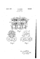
tional viewtaken through one of my friction or tension rollers anda part of the conveyor chain to which itis secured. FlQHI'QQ is an end view of the same. -And Figure- 3 is a cross sectional view takenthrough the fric- 45 tion roller assembly on theline 3-3 of Figure 1.
. Referring to the accompanying drawings fora detailed description of my inventlon, the numeral 1 designates apart of acon-,
ventional conveyor chain. comprising chain rollers 1, pins 2, roller links 3 and pin llnks t.
Secured to each of the'conveyor chain, against each end roller l1nk 3, are the apertured ends of the cross portion of an inverted T shaped saddle mem- I her .5; Each, saddlemember 5 is formed in' its outer end with ahole to receive one end pf a friction roller shaft'6 which is D shaped in cross section to provide a fiat surface 7 on its periphery.
Upon the shaft'fi supported by'each pair of saddle members '5, 5,.a' friction roller 8 is mounted out of contact with the chain rollers ,1 and the links 3 and 4. The friction roller:
member-open at both 8, consisting 10f hollow ends, is formed with a central portion 9. of reduced Jchameter on its interior surface, to
provide at the ends thereof a two annular shoulders 10, 10. p Y
Surrounding the middle portion of the shaft v6, within the space defined by the cen-' tral part 9 of the friction roller 8,;is a helical spring 11. At eac'hend this spring is in pressure engagement with a D washer 12 preferably constructed of steel and secured against rotation on the shaft 6 because itis alsoof D shape in cross section.
In friction engagement with the outer face of each fixed D- washer 12 is a braking washer.
13 preferably constructed of fiber and freely mounted ontheShaft 6. The, outer faces of these friction washers 13, 13, are in braking engagement with two large steel washers 14, 14, respectively, which fit against the annular shoulders 10, 10 in the ends of the friction roller 8 for rotation with it. around the shaft. i
pair of adjacent pins 2, 2 w
Between each steel washer 1 1 and its adja-' I cent saddle member 5, there is fitted on the shaft 6 an inner race member 15 for ball bearings 16. 1 These race .members 15, v15 are prevented from turning by copper rivets 17 -whi'ch they carry :forengageme'nt at their foot portions with" the flat surface on the shaft. 7 Surrounding the axially inner portions of the- race members 15,15, for a free rotation upon the balls'16, are outer race members 18,
18 respectively. These outer race members are formed at their axially outer 'ends with radially inturnedfianges 19 for entrance into annular grooves 20 provided in the radially outer peripheries of the inner race members 15. These flanges 19 prevent the entrance of dust and dirt into the interior of the friction roller 8.
The friction roller assembly just described is secured together by a tail flange 21 on one end of the shaft 6, which engages its respective saddle member 5, and by a co-ooerating nut 22 applied to the opposite end of the shaft, for engagement with the other saddle member 5. \Vhen the nut is drawn tight on the threaded end of the shaft 6, the outer race members 18 will be in sufficiently firm en gagemcnt with the steel washers 1d, 14 to turn with them around the shaft.
Through their engagement with the fiat surfaces of objects, such as metal sheets, these friction rollers 8. which will be held against rotation by the braking washers 13 until the sheets are stopped, will move the latter forward so long as the conveyor chains are in motion. If, on the other hand, these sheets are stopped by disappearing gages, or other means, the conveyor chains will. continue their forward movement while the tension rollers 8, now overcoming the braking action of the spring pressed fiber washers 13, roll along the surface of these stationary sheets. But when these gages disappear, the tension rollers 8 will again be held against rotation by the braking action of the fiber washers, to pick up the sheets and move them forward instantly.
Having described my invention, I claim:
1. In a device of the type described, a conveyor for a sheet, a tension roller on said conveyor for engaging the surface of said sheet, and friction means for holding said roller against rotation until the sheet stops, whereupon it will roll along the surface of the stationary sheet to permit the conveyor to continue its forward movement.
2. In a device of the type described, a conveyor for asheet, a tension roller on said conveyor for engaging the surface of said sheet, said. roller adapted to roll against the surface of the sheet when the latter is stopped. and friction means on said roller to stop its rotation to pick up and move the sheet forward instantly the latter is released.
3. A tension roller of the type described, comprising a hollow cylindrical member, a shaft upon which said roller is mounted, a hearing at each end of the shaft for said roller, and braking means between the bearings within the roller to frictionally resist its rotation around the shaft.
4. tension roller of the type described, comprising a hollow cylindrical member, a shaft upon which said roller mounted, a bearing at each end of the shaft for said roller, a pair of spaced braking means between the bearings within the roller, and a spring surrounding the shaft between and in engagement with the braking means, to urge them outwardly to resist the rotation of the roller around the shaft.
5. A tension roller of the type described, comprising a hollow cylindrical member, a shaft upon which said roller is mounted, a hearing at each end of the shaft for said roller, said bearing including an inner stationary part and an outer rotatable part, a metal washer on said shaft free to move around the latter with each rotatable part of the bearing, a friction washer in engagement with each metal washer, and a helical spring surrounding the shaft between the friction washers for pressing them into engagement with the metal washers to resist the rotation of the roller around the shaft.
6. A tension roller of the type described, comprising a hollow cylindrical member open at both ends, which said roller is mounted, a hearing at each end of the shaft for said roller, said bearing including an inner stationary part and an outer rotatable part, a metal washer on said shaft free to move around the latter with each rotatable part of the bearing, a friction washer in engagement with each metal washer, a metal D washer mounted on the shaft for engagement with each friction washer, and a helical spring surrounding the shaft between, and in engagement with, the D washer for the purpose specified.
7. A tension roller of the type described, comprising a hollow cylindrical member open at both ends, a shaft of D cross section upon which said roller is mounted, a bearing at each end of the shaft for said roller, said bearing including an inner race-way and an outer race-way, a radial element carried by each inner race-way for engagement with the flat on the shaft, ball bearings in said raceways, two annular spaced shoulders formed on the interior surface of said roller, a metal washer free to turn on said shaft between each shoulder and the race-ways, said washer fitting tightly against its respective inner race-way, a friction washer in engagement with each metal washer, a metal D washer mounted on the shaft for engagement with each friction washer, and a helical spring surrounding the shaft between, and in engagement with, the D washers, for the purpose specified.
8. In a device of the type described, the combination with a pair of adjacent chain roller assemblies, a pin projecting through each chain roller assembly, a pair of saddle members connected by said pins to said chain roller assemblies, a shaft secured to said saddle members in parallelism with said chain roller assemblies, a bearing secured to each end of said shaft in the space between the saddle members, a tension roller mounted on said bearings for rotation around said shaft, and friction means surrounding said shaft a shaft of D cross section upon" being formed with an axial hole,
between the bearings to resist the rotation of the tension roller.
9. In a device of the type described, the i combination with a pair of adjacent roller assemblies, a pin projecting through each formed on one end of said shaft for en- I gagement with its respective saddle member,
a nut applied to the other end of said shaft for engagement with its respective saddle member, a bearing secured to each end of said shaft, said bearings being spaced from each other and being between said saddle members, friction means surrounding said shaft for en- 7 gagment with the movable part of each bearmg, and a coil spr ng surrounding said shaft between the friction means to urge them outwardly for the purpose specified.
Intestimony whereof I have hereunto set my hand this 3rd day of August, 1931.
FRANK B; STREINE.
Priority Applications (4)
| Application Number | Priority Date | Filing Date | Title |
|---|---|---|---|
| US555247A US1852942A (en) | 1931-08-05 | 1931-08-05 | Friction roller |
| DEST49622D DE592901C (en) | 1931-08-05 | 1932-07-24 | Support rollers for conveyor pieces arranged on a conveyor |
| GB20902/32A GB392020A (en) | 1931-08-05 | 1932-07-25 | Improvements in conveyors |
| FR740531D FR740531A (en) | 1931-08-05 | 1932-07-27 | Friction roller refinements |
Applications Claiming Priority (1)
| Application Number | Priority Date | Filing Date | Title |
|---|---|---|---|
| US555247A US1852942A (en) | 1931-08-05 | 1931-08-05 | Friction roller |
Publications (1)
| Publication Number | Publication Date |
|---|---|
| US1852942A true US1852942A (en) | 1932-04-05 |
Family
ID=24216556
Family Applications (1)
| Application Number | Title | Priority Date | Filing Date |
|---|---|---|---|
| US555247A Expired - Lifetime US1852942A (en) | 1931-08-05 | 1931-08-05 | Friction roller |
Country Status (4)
| Country | Link |
|---|---|
| US (1) | US1852942A (en) |
| DE (1) | DE592901C (en) |
| FR (1) | FR740531A (en) |
| GB (1) | GB392020A (en) |
Cited By (22)
| Publication number | Priority date | Publication date | Assignee | Title |
|---|---|---|---|---|
| US2602536A (en) * | 1949-03-28 | 1952-07-08 | Standard Conveyor Co | Live roller conveyer |
| US3092262A (en) * | 1959-01-12 | 1963-06-04 | Planet Corp | Article transfer system |
| US3503490A (en) * | 1968-01-05 | 1970-03-31 | Owens Illinois Inc | Descending accumulating conveyor |
| US3527087A (en) * | 1968-03-29 | 1970-09-08 | Scans Associates Inc | Automated engine test conveyor |
| US3631967A (en) * | 1970-07-15 | 1972-01-04 | Scans Associates Inc | Accumulator conveyor system |
| US3648819A (en) * | 1968-03-29 | 1972-03-14 | Scans Associates Inc | Industrial system and method |
| USB449647I5 (en) * | 1974-03-11 | 1975-01-28 | ||
| US4836357A (en) * | 1982-08-31 | 1989-06-06 | Focke & Co. | Continuous conveyor, especially a carrying chain conveyor |
| US5038921A (en) * | 1989-05-25 | 1991-08-13 | Hoppmann Corporation | Transport carrier conveyor |
| US5040668A (en) * | 1989-05-25 | 1991-08-20 | Hoppmann Corporation | Transport carrier conveyor |
| US5064054A (en) * | 1989-05-25 | 1991-11-12 | Hoppmann Corporation | Overlapping flat surface transport carrier conveyor |
| US5096050A (en) * | 1981-06-02 | 1992-03-17 | Rexnord Corporation | Low backline pressure chain |
| DE4117509C1 (en) * | 1991-05-24 | 1992-07-16 | Mannesmann Ag, 4000 Duesseldorf, De | Buffer conveyor with transverse bores in belt - has roller holders on support roller axis, each swivelably mounted |
| US6062378A (en) * | 1998-01-28 | 2000-05-16 | Tekno, Inc. | Accumulating conveyor chain with controlled friction |
| US6168011B1 (en) | 1998-01-30 | 2001-01-02 | Sws Scharf-Westfalia Industrial Systems Gmbh | Accumulation conveyor system |
| US6237755B1 (en) | 1997-06-19 | 2001-05-29 | Tekno, Inc. | Chain drive with adjustable friction |
| US20090250320A1 (en) * | 2008-03-28 | 2009-10-08 | Dieter Steinstrater | Chain link module for accumulating chain |
| US20100054889A1 (en) * | 2008-08-28 | 2010-03-04 | Goodrich Corporation | Attenuated cargo caster |
| US8225922B1 (en) * | 2011-03-10 | 2012-07-24 | Laitram, L.L.C. | Transverse driven-roller belt and conveyor |
| US9352908B1 (en) * | 2014-12-03 | 2016-05-31 | Laitram, L.L.C. | Stacked-roller belt conveyor with zone control |
| WO2017055999A3 (en) * | 2015-09-28 | 2017-05-04 | Regina Catene Calibrate S.P.A. | Module for a modular conveyor belt with a roller conveyor surface and modular conveyor belt formed by a plurality of such modules |
| US20220315344A1 (en) * | 2019-08-07 | 2022-10-06 | Laitram, L.L.C. | Roller belt with support edges |
Families Citing this family (5)
| Publication number | Priority date | Publication date | Assignee | Title |
|---|---|---|---|---|
| DE1074496B (en) * | 1960-01-28 | Salzgitter Industriebau Gesell schaft mbH, Salzgitter-Drutte | Vornch tion for stacking and transverse transport of metal sheets under a magnetic roller table | |
| DE1037782B (en) * | 1954-06-09 | 1958-08-28 | Monforts Maschinenfabrik A | Device for braking a shaft, in particular a guide roller for textile, web-like goods |
| DE1189917B (en) * | 1962-03-08 | 1965-03-25 | Electrolux Ab | Brake roller for a roller table formed from support rollers lying one behind the other |
| DE4328978C2 (en) * | 1993-08-28 | 1995-12-21 | Daimler Benz Aerospace Airbus | Device for carrying cargo units in cargo loading systems |
| DE202004021634U1 (en) * | 2004-02-28 | 2009-09-03 | Stotz Fördersysteme GmbH | Roller conveyors |
-
1931
- 1931-08-05 US US555247A patent/US1852942A/en not_active Expired - Lifetime
-
1932
- 1932-07-24 DE DEST49622D patent/DE592901C/en not_active Expired
- 1932-07-25 GB GB20902/32A patent/GB392020A/en not_active Expired
- 1932-07-27 FR FR740531D patent/FR740531A/en not_active Expired
Cited By (31)
| Publication number | Priority date | Publication date | Assignee | Title |
|---|---|---|---|---|
| US2602536A (en) * | 1949-03-28 | 1952-07-08 | Standard Conveyor Co | Live roller conveyer |
| US3092262A (en) * | 1959-01-12 | 1963-06-04 | Planet Corp | Article transfer system |
| US3503490A (en) * | 1968-01-05 | 1970-03-31 | Owens Illinois Inc | Descending accumulating conveyor |
| US3527087A (en) * | 1968-03-29 | 1970-09-08 | Scans Associates Inc | Automated engine test conveyor |
| US3648819A (en) * | 1968-03-29 | 1972-03-14 | Scans Associates Inc | Industrial system and method |
| US3631967A (en) * | 1970-07-15 | 1972-01-04 | Scans Associates Inc | Accumulator conveyor system |
| USB449647I5 (en) * | 1974-03-11 | 1975-01-28 | ||
| US3916797A (en) * | 1974-03-11 | 1975-11-04 | Rockford Automation | Power driven conveyor |
| US5096050A (en) * | 1981-06-02 | 1992-03-17 | Rexnord Corporation | Low backline pressure chain |
| US4836357A (en) * | 1982-08-31 | 1989-06-06 | Focke & Co. | Continuous conveyor, especially a carrying chain conveyor |
| US5038921A (en) * | 1989-05-25 | 1991-08-13 | Hoppmann Corporation | Transport carrier conveyor |
| US5040668A (en) * | 1989-05-25 | 1991-08-20 | Hoppmann Corporation | Transport carrier conveyor |
| US5064054A (en) * | 1989-05-25 | 1991-11-12 | Hoppmann Corporation | Overlapping flat surface transport carrier conveyor |
| DE4117509C1 (en) * | 1991-05-24 | 1992-07-16 | Mannesmann Ag, 4000 Duesseldorf, De | Buffer conveyor with transverse bores in belt - has roller holders on support roller axis, each swivelably mounted |
| US6237755B1 (en) | 1997-06-19 | 2001-05-29 | Tekno, Inc. | Chain drive with adjustable friction |
| US6062378A (en) * | 1998-01-28 | 2000-05-16 | Tekno, Inc. | Accumulating conveyor chain with controlled friction |
| US6168011B1 (en) | 1998-01-30 | 2001-01-02 | Sws Scharf-Westfalia Industrial Systems Gmbh | Accumulation conveyor system |
| US20090250320A1 (en) * | 2008-03-28 | 2009-10-08 | Dieter Steinstrater | Chain link module for accumulating chain |
| US8499926B2 (en) * | 2008-03-28 | 2013-08-06 | Ammeraal Beltech Modular A/S | Chain link module for accumulating chain |
| US20100054889A1 (en) * | 2008-08-28 | 2010-03-04 | Goodrich Corporation | Attenuated cargo caster |
| US8109702B2 (en) | 2008-08-28 | 2012-02-07 | Goodrich Corporation | Attenuated cargo caster |
| US8225922B1 (en) * | 2011-03-10 | 2012-07-24 | Laitram, L.L.C. | Transverse driven-roller belt and conveyor |
| US9352908B1 (en) * | 2014-12-03 | 2016-05-31 | Laitram, L.L.C. | Stacked-roller belt conveyor with zone control |
| WO2017055999A3 (en) * | 2015-09-28 | 2017-05-04 | Regina Catene Calibrate S.P.A. | Module for a modular conveyor belt with a roller conveyor surface and modular conveyor belt formed by a plurality of such modules |
| KR20180059462A (en) * | 2015-09-28 | 2018-06-04 | 레지나 카테네 칼리브레이트 에스.피.에이. | A modular conveyor belt module having a roller conveyor surface and a modular conveyor belt formed by such a plurality of modules |
| CN108137236A (en) * | 2015-09-28 | 2018-06-08 | 意大利雷吉那链条集团 | Module and the modular plastic conveyor belts that are formed by multiple this modules for the modular plastic conveyor belts with roller conveyer surface |
| US10604346B2 (en) | 2015-09-28 | 2020-03-31 | Regina Catene Calibrate S.P.A. | Module for a modular conveyor belt with a roller conveyor surface and modular conveyor belt formed by a plurality of such modules |
| RU2720921C2 (en) * | 2015-09-28 | 2020-05-14 | Реджина Катене Калибрате С.П.А. | Module for modular conveyor belt with roller conveyor surface and modular conveyor belt formed from a plurality of such modules |
| KR102540527B1 (en) | 2015-09-28 | 2023-06-05 | 레지나 카테네 칼리브레이트 에스.피.에이. | A module for a modular conveyor belt having a roller conveyor surface and a modular conveyor belt formed by a plurality of such modules |
| US20220315344A1 (en) * | 2019-08-07 | 2022-10-06 | Laitram, L.L.C. | Roller belt with support edges |
| US11905118B2 (en) * | 2019-08-07 | 2024-02-20 | Laitram, L.L.C. | Roller belt with support edges |
Also Published As
| Publication number | Publication date |
|---|---|
| GB392020A (en) | 1933-05-11 |
| DE592901C (en) | 1934-02-17 |
| FR740531A (en) | 1933-01-27 |
Similar Documents
| Publication | Publication Date | Title |
|---|---|---|
| US1852942A (en) | Friction roller | |
| US1746978A (en) | Adapter for bearings | |
| US3240542A (en) | Roller thrust bearing | |
| US1627558A (en) | Sheave | |
| US3011606A (en) | Roller clutch | |
| US4006815A (en) | Article transporting conveyor | |
| US2262325A (en) | Self-aligning return roller for belt conveyers | |
| US4143525A (en) | Accumulating roll conveyor | |
| US2044663A (en) | Cage for antifriction bearings | |
| US2823967A (en) | Bearing | |
| US569632A (en) | Drive-chain | |
| US2467437A (en) | Skate wheel structure | |
| US2193549A (en) | Steering column bushing | |
| JP6392031B2 (en) | Side roller and chain with side roller | |
| US2188862A (en) | Locomotive valve gear bearing | |
| US3051013A (en) | Forward and reverse friction drive tapping attachment | |
| US2900051A (en) | Cam roller self-energizing disc brake | |
| US718111A (en) | Antifriction end-thrust device. | |
| US1837415A (en) | Antifriction bearing | |
| US2818952A (en) | Lever design for spring-loaded clutch | |
| US1857252A (en) | Ball or roller clutch | |
| US1270820A (en) | Roller-bearing. | |
| US2888115A (en) | Combined clutch and brake | |
| US3127203A (en) | poundstone | |
| US1280621A (en) | Antifriction-bearing. |