US1852940A - Avocado picker - Google Patents
Avocado picker Download PDFInfo
- Publication number
- US1852940A US1852940A US505434A US50543430A US1852940A US 1852940 A US1852940 A US 1852940A US 505434 A US505434 A US 505434A US 50543430 A US50543430 A US 50543430A US 1852940 A US1852940 A US 1852940A
- Authority
- US
- United States
- Prior art keywords
- receptacle
- fruit
- pole
- container
- avocado
- Prior art date
- Legal status (The legal status is an assumption and is not a legal conclusion. Google has not performed a legal analysis and makes no representation as to the accuracy of the status listed.)
- Expired - Lifetime
Links
- 235000008673 Persea americana Nutrition 0.000 title description 4
- 240000002426 Persea americana var. drymifolia Species 0.000 title 1
- 235000013399 edible fruits Nutrition 0.000 description 18
- 244000025272 Persea americana Species 0.000 description 3
- 238000010276 construction Methods 0.000 description 3
- 238000010008 shearing Methods 0.000 description 2
- 230000005089 fruit drop Effects 0.000 description 1
- 238000004519 manufacturing process Methods 0.000 description 1
- 230000004048 modification Effects 0.000 description 1
- 238000012986 modification Methods 0.000 description 1
- 230000002093 peripheral effect Effects 0.000 description 1
- 230000000284 resting effect Effects 0.000 description 1
Images
Classifications
-
- A—HUMAN NECESSITIES
- A01—AGRICULTURE; FORESTRY; ANIMAL HUSBANDRY; HUNTING; TRAPPING; FISHING
- A01D—HARVESTING; MOWING
- A01D46/00—Picking of fruits, vegetables, hops, or the like; Devices for shaking trees or shrubs
- A01D46/24—Devices for picking apples or like fruit
- A01D46/247—Manually operated fruit-picking tools
Definitions
- This invention relates to a fruit "harvester particularly adapted for picking avocados, and has for its primary object to provide, ina manner as hereinafter set forth, :a device of 5 such character by means of which a given quantity of fruit may be picked in a shorter length of time than is possible by anyother means known to. the industry, thereby materiallyreducing the labor cost of picking the fruit.
- e V i A further object of the invention is to provide, in a manner as hereinafter set forth, a deviceof'the character aforesaid which includes means for assembling the picked fruit in a container therefor without any likelihood of .the fruit becoming bruised during the picking thereof. 1
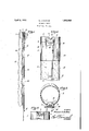
- Figure 1 is a side elevation of a fruit har- "vester in accordance with this invention.
- Figure 2 is an enlarged fragmentary front elevation thereof.
- FigureS is an enlarged top plan thereof.
- 7 Figure 4 is an enlarged fragmentary front "elevation of the receptacle for receiving the picked fruit.
- the numeral 1 indicates a rigid receptacle which c is open at its top and bottom.
- the receptacle '1 preferablyis of cylindrical construction
- the receptacle 1 is detachably mounted in any suitablemanner on the upper end of a rigid pole 4 in order that the receptacle maybe elevated a material distance from the ground during the use of the harvester.
- the mounting as shown for securingthe receptacle to the pole includes a sleeve 5 which has an upper end 1 portion, of the pole extended therein, the sleeve having a peripheral portion; thereof disposed within the projecting portion 2' of the interior of the: container, and being formed with a rearwardly and downwardly sloping-upper end indicated atc6.
- a substantially V-shaped notch 7 which opens through the upper edge of thewall portion 3.
- Fixedly securedito the outer face of the wall portion 3 is a stationarycutting blade 8, the cutting edge 9 of which projects beyond and extends in parallel relation to one of the walls of the notch 7.
- a movable blade 10 Pivotally connected to the stationary blade 18 and to the Wall portion 3, bymeans of asuitable pivot pin 9, is a movable blade 10 which is. substantially in the form of a bell crank, and the cutting edge 11 of which is normally projected beyond and in parallel relation to the wall of the notch 7'which is opposite the cuttingedge 9 of the stationary blade 8.
- Pivotally connected to the end of the blade 10 which is opposite the cutting edge 11 is an angular ,rod'l2 which extends downwardly and the lower end of which is connected with a cable 13'.
- the cut. ting edge 11 isnormally maintained inspaced relation to the cutting edge 9 by means of a coiled spring 14, one end of which is secured to the blade'lO and the otherend of which is secured to the wall portion3.
- the blade10 Upon the exertionofa dowward force on the rod 12, the blade10 is swung about its 'pivot whereby the cutting edge 11 is advanced toward and edge '9 i111 shearing rela Upon the release of the 100 P TENT QFFIGEQ downward force on the rod 12, the cutting edge 11 is returned to its normal position by the action of the spring 14:.
- the cable 13 In order that a downward force may be exerted on the rod 12, remotely therefrom, the cable 13 is extended longitudinally of the pole 4, being maintained in position by meansof suitable guides 15 projecting from the pole 4 at spaced points longitudinally of the latter.
- the cable 13 will be provided at its lower end with a suitable gripmcmber v16.
- a con tainer 17 which is substantially in the form of an elongated sack having an open upper end which is inserted within the receptacle 1 and is suitably secured therein with the upper edge portion of the sack resting against and extending above the sloping upper end 6 of the sleeve 5.
- the container is secured to the pole 4, as indicated at 18, whereby the container is main tained substantially in parallel relation to the pole. Owing to the connection 18, there is a tendency for the wall of the container to extend in a series of slight curves which tend to break the fall of the fruit.
- the receptacle 1 In the operation of the device, the receptacle 1 is positioned beneath and around the fruit to be picked with the stem of the fruit projecting between the spaced cutting edges 9 and 11 of the blades 8 and 10 respectively.
- the cutting edge 11 isthen moved into shearing relation to the cutting edge 9 by the exertion of a downward force on the cable 13 to sever the stem supporting the fruit.
- the fruit drops through the receptacle 1 and into the container 17.
- a fruit harvester comprising, a rigid receptacle adapted to be positioned beneath fruit to be picked, said receptacle being of cylindrical construction and having a laterally projecting portion extending throughout the length thereof, a cutting device carried by the laterally projecting portion of the receptacle and having a pair of cutting edges disposed above adjacent portions of the receptacle, a pole upon which the receptacle is mounted, said pole being extended into to be picked, a stem cutting device carried by the receptacle, a pole extending into and secured to the receptacle adjacent the wall thereof, said pole havingan inclined up er end face sloping downwardly and inwardly from said wall, a container for receiv' the fruit from the receptacle, saidcontainiaifiwving a portion thereof adjacent its upper edge extended across the inclined upperend faceof the pole,,andn 1eans foroperatingthe stem cutting device.
Landscapes
- Life Sciences & Earth Sciences (AREA)
- Environmental Sciences (AREA)
- Apparatuses For Bulk Treatment Of Fruits And Vegetables And Apparatuses For Preparing Feeds (AREA)
Description
April 5, 1932.
E J. STATOM AVOCADO PICKER Filed Dec. 29 1930 n m m m Edward (1.3573157?! A TTORNEY.
Patented Apr. 5, .1932 1 V -EDWARDJ. STATOM, OF ALTA LOMA, CALIFORNIA V AvocADo rrcxnn Application filed December 29, 1930.. Serial No. 505,434.
This invention relates to a fruit "harvester particularly adapted for picking avocados, and has for its primary object to provide, ina manner as hereinafter set forth, :a device of 5 such character by means of which a given quantity of fruit may be picked in a shorter length of time than is possible by anyother means known to. the industry, thereby materiallyreducing the labor cost of picking the fruit. e V i A further object of the invention is to provide, in a manner as hereinafter set forth, a deviceof'the character aforesaid which includes means for assembling the picked fruit in a container therefor without any likelihood of .the fruit becoming bruised during the picking thereof. 1
Further objects of the invention are to provide, in a manner as hereinafter set forth, a fruit harvester of the character aforesaid which is comparatively simple in its con-r struction and arrangement of parts, strong, durable, compact, thoroughly eflicient in its intended use, and comparatively inexpensive to manufacture.
With the foregoing and other'objects in view, the invention consists of the novel construction, combination and arrangement of parts as hereinafter more specifically described, and illustrated in the accompanying drawings, whereinis shown an embodiment of the invention, but. it is to be understood that changes, variations and modifications 7 can be resorted to which fall withinthe scope of the claims hereunto appended.
In the drawings wherein like reference characters denote corresponding parts throughout the several views I .Figure 1 is a side elevation of a fruit har- "vester in accordance with this invention. Figure 2 is an enlarged fragmentary front elevation thereof.
FigureS is an enlarged top plan thereof. 7 Figure 4 is an enlarged fragmentary front "elevation of the receptacle for receiving the picked fruit.
Referring to thesdrawings in detail, the numeral 1 indicates a rigid receptacle which c is open at its top and bottom. The receptacle '1 preferablyis of cylindrical construction,
-- beyond the cutting .tionto the latter."
having its wall formed throughout the length of the receptacle with a laterally offset portion which provides the interior of the recep taclewith an outwardly projectingportion 2 substantially rectangular in, cross section. The offset portion of the wall of the recep tacle is indicated by the numeral 3. The receptacle 1 is detachably mounted in any suitablemanner on the upper end of a rigid pole 4 in order that the receptacle maybe elevated a material distance from the ground during the use of the harvester. The mounting as shown for securingthe receptacle to the pole includes a sleeve 5 which has an upper end 1 portion, of the pole extended therein, the sleeve having a peripheral portion; thereof disposed within the projecting portion 2' of the interior of the: container, and being formed with a rearwardly and downwardly sloping-upper end indicated atc6. Formed in the offset wall portion?) of the container is a substantially V-shaped notch 7 which opens through the upper edge of thewall portion 3. Fixedly securedito the outer face of the wall portion 3 is a stationarycutting blade 8, the cutting edge 9 of which projects beyond and extends in parallel relation to one of the walls of the notch 7. Pivotally connected to the stationary blade 18 and to the Wall portion 3, bymeans of asuitable pivot pin 9, is a movable blade 10 which is. substantially in the form of a bell crank, and the cutting edge 11 of which is normally projected beyond and in parallel relation to the wall of the notch 7'which is opposite the cuttingedge 9 of the stationary blade 8. Pivotally connected to the end of the blade 10 which is opposite the cutting edge 11 is an angular ,rod'l2 which extends downwardly and the lower end of which is connected with a cable 13'. The cut. ting edge 11 isnormally maintained inspaced relation to the cutting edge 9 by means of a coiled spring 14, one end of which is secured to the blade'lO and the otherend of which is secured to the wall portion3. Upon the exertionofa dowward force on the rod 12, the blade10 is swung about its 'pivot whereby the cutting edge 11 is advanced toward and edge '9 i111 shearing rela Upon the release of the 100 P TENT QFFIGEQ downward force on the rod 12, the cutting edge 11 is returned to its normal position by the action of the spring 14:. In order that a downward force may be exerted on the rod 12, remotely therefrom, the cable 13 is extended longitudinally of the pole 4, being maintained in position by meansof suitable guides 15 projecting from the pole 4 at spaced points longitudinally of the latter. Preferably the cable 13 will be provided at its lower end with a suitable gripmcmber v16.
Connected with the receptacle 1 is a con tainer 17 which is substantially in the form of an elongated sack having an open upper end which is inserted within the receptacle 1 and is suitably secured therein with the upper edge portion of the sack resting against and extending above the sloping upper end 6 of the sleeve 5. At spaced points thereof, the container is secured to the pole 4, as indicated at 18, whereby the container is main tained substantially in parallel relation to the pole. Owing to the connection 18, there is a tendency for the wall of the container to extend in a series of slight curves which tend to break the fall of the fruit.
In the operation of the device, the receptacle 1 is positioned beneath and around the fruit to be picked with the stem of the fruit projecting between the spaced cutting edges 9 and 11 of the blades 8 and 10 respectively. The cutting edge 11 isthen moved into shearing relation to the cutting edge 9 by the exertion of a downward force on the cable 13 to sever the stem supporting the fruit. The fruit drops through the receptacle 1 and into the container 17. Owing to the inclined upper face of the pole, and to the extension of the container over such face, a smooth surface is presented to the falling fruit, and any possibility of the fruit being bruised by the upper end of the pole or container is imina e It is thought that the many advantages of a fruit harvester in accordance with this invention will be readily apparent, and although the preferred embodiment of the invention is as illustrated and described, it is to be understood that changes in the size, shape and arrangement of parts may be resorted to, so long as such changes fall within the scope of the invention as defined in the appended claims.
What I claim is 1. A fruit harvester comprising, a rigid receptacle adapted to be positioned beneath fruit to be picked, said receptacle being of cylindrical construction and having a laterally projecting portion extending throughout the length thereof, a cutting device carried by the laterally projecting portion of the receptacle and having a pair of cutting edges disposed above adjacent portions of the receptacle, a pole upon which the receptacle is mounted, said pole being extended into to be picked, a stem cutting device carried by the receptacle, a pole extending into and secured to the receptacle adjacent the wall thereof, said pole havingan inclined up er end face sloping downwardly and inwardly from said wall, a container for receiv' the fruit from the receptacle, saidcontainiaifiwving a portion thereof adjacent its upper edge extended across the inclined upperend faceof the pole,,andn 1eans foroperatingthe stem cutting device.
In testimony whereof, Iafiixmy signature hereto.
J. S ATOM.
Priority Applications (1)
| Application Number | Priority Date | Filing Date | Title |
|---|---|---|---|
| US505434A US1852940A (en) | 1930-12-29 | 1930-12-29 | Avocado picker |
Applications Claiming Priority (1)
| Application Number | Priority Date | Filing Date | Title |
|---|---|---|---|
| US505434A US1852940A (en) | 1930-12-29 | 1930-12-29 | Avocado picker |
Publications (1)
| Publication Number | Publication Date |
|---|---|
| US1852940A true US1852940A (en) | 1932-04-05 |
Family
ID=24010298
Family Applications (1)
| Application Number | Title | Priority Date | Filing Date |
|---|---|---|---|
| US505434A Expired - Lifetime US1852940A (en) | 1930-12-29 | 1930-12-29 | Avocado picker |
Country Status (1)
| Country | Link |
|---|---|
| US (1) | US1852940A (en) |
Cited By (1)
| Publication number | Priority date | Publication date | Assignee | Title |
|---|---|---|---|---|
| US3998038A (en) * | 1975-09-02 | 1976-12-21 | Root Arthur A | Fruit picker |
-
1930
- 1930-12-29 US US505434A patent/US1852940A/en not_active Expired - Lifetime
Cited By (1)
| Publication number | Priority date | Publication date | Assignee | Title |
|---|---|---|---|---|
| US3998038A (en) * | 1975-09-02 | 1976-12-21 | Root Arthur A | Fruit picker |
Similar Documents
| Publication | Publication Date | Title |
|---|---|---|
| US2228536A (en) | Can holder and perforator | |
| US4226075A (en) | Fruit picking apparatus | |
| US3183031A (en) | Paper and rubbish pick-up | |
| US2254738A (en) | Cutting tool | |
| US1852940A (en) | Avocado picker | |
| US2250236A (en) | Double cutter dispensing container | |
| US2282150A (en) | Opening and dispensing device | |
| US3449896A (en) | Fruit picking device | |
| US1981388A (en) | Twine-dispensing device | |
| US1558774A (en) | Berry picker | |
| US2188768A (en) | Harvesting device | |
| US2367105A (en) | Paper picker | |
| US2746232A (en) | Pole supported fruit picker with pivoted cutter | |
| US1537537A (en) | Edge trimmer for lawns | |
| US2346986A (en) | Fruit clipping device | |
| US1551057A (en) | Strawberry picker | |
| US2159122A (en) | Golf ball holder | |
| US2260836A (en) | Egg opener | |
| US1757073A (en) | Culinary knife | |
| US2142197A (en) | Fish knife | |
| US3638409A (en) | Fruit picker | |
| US1514680A (en) | Tool for cutting bananas from bunches thereof | |
| US2630850A (en) | Support for use in cutting radishes | |
| US1538398A (en) | Grapefruit-coring implement | |
| US1805387A (en) | Ice cream scoop |