US1852938A - Coil - Google Patents
Coil Download PDFInfo
- Publication number
- US1852938A US1852938A US483690A US48369030A US1852938A US 1852938 A US1852938 A US 1852938A US 483690 A US483690 A US 483690A US 48369030 A US48369030 A US 48369030A US 1852938 A US1852938 A US 1852938A
- Authority
- US
- United States
- Prior art keywords
- coil
- convolutions
- rack bar
- spaces
- adjacent
- Prior art date
- Legal status (The legal status is an assumption and is not a legal conclusion. Google has not performed a legal analysis and makes no representation as to the accuracy of the status listed.)
- Expired - Lifetime
Links
- 239000004020 conductor Substances 0.000 description 4
- 238000010276 construction Methods 0.000 description 2
- 239000011810 insulating material Substances 0.000 description 1
- 238000004804 winding Methods 0.000 description 1
Images
Classifications
-
- H—ELECTRICITY
- H01—ELECTRIC ELEMENTS
- H01F—MAGNETS; INDUCTANCES; TRANSFORMERS; SELECTION OF MATERIALS FOR THEIR MAGNETIC PROPERTIES
- H01F21/00—Variable inductances or transformers of the signal type
- H01F21/12—Variable inductances or transformers of the signal type discontinuously variable, e.g. tapped
Definitions
- This invention relates to improvements in electric coils, the general object of the invention being to provide means for adjusting the length of the coil while eliminating dead end losses by providing means for preventing any current from passing through the convolutions of the coil which are not in use.
- Figure 2 is a view taken at right angles to Figure 1.
- Figure 3 is a top plan view.
- Figure 4 is a section on line l l of Figure 1.
- Figure 5 is a section on line 55 of Figure 1.
- each convolution of the coil A is formed continuous by a space 2 which supports the adjacent or meeting ends of the coil.
- a rack bar 3 has a part 4 adapted to move between the ends of the sections, and in order to permit the rack bar to connect all the sections of the coil together when desired, the spaces 2 are placed in alignment, as shown, and the adjacent ends of the sections of the convolutions are bent outwardly, as shown at 5, to receive the part 4 of the rack bar.
- the rack bar is formed of insulating material and conductors 6 are carried by the part 4 for bridging the spaces 2.
- these conductors 6 are spaced the same distance as are the convolutions of the coil so that by moving the rack bar into or from the row of spaces 2, any nimiber of the convolutions of the coil can have their sections eonnected together by the conductors 6.
- the rack bar is adjusted through means of a pinion 7 on a shaft 8 which is provided with a handle 9 so that it can be turned in either direction to cause the pinion to move the rack bar in either direction.
- the drawings show a pair of these rack bars for adjusting the length of a pair of coils.
- This invention may be used in any device or wherever it is desired to adjust the length of a coil or coils or the number of windings of the coils which are to be electrically connected together.
- a coil comprising a series of convolutions, each convolution having outwardly bent portions providing a space between and adjacent the ends thereof, and means for bridging the spaces of any desired number of convolutions.
- a coil comprising a series of convolutions, each convolution having outwardly bent portions providing a space between and adjacent the ends thereof, means for bridging the spaces of any desired number of convolutions, said means comprising a rack bar, conductors carried by the rack bar and electrically connecting the adjacent ends of the convolutions together, a pinion meshing with the bar and a shaft for rotating the pinion.
- a coil comprising a. series of convolutions, each convolution having outwardly bent portions providing a space between and adjacent the ends thereof, and slidable means for bridging the spaces of any desired number of convolutions.
- a coil comprising a series of convolutions, each convolution having outwardly bent portions providing a space between and adjacent the ends thereof, and oppositely slidable means for bridging the spaces of any desired number of convolutions.
Landscapes
- Engineering & Computer Science (AREA)
- Power Engineering (AREA)
- Coils Or Transformers For Communication (AREA)
- Magnetic Resonance Imaging Apparatus (AREA)
Description
April 5, 1932 SAMUEL H 1,852,938
COIL
Filed Sept. 22, 1930 7 Fi .5. f gdi INVENTOR v ATTORNEY Patented Apr. 5, 1932 UNITED STATES RICHARD H. SAMUEL, OF HOBOKEN, NEW JERSEY COIL Application filed September 22, 1930. Serial No. 483,690.
This invention relates to improvements in electric coils, the general object of the invention being to provide means for adjusting the length of the coil while eliminating dead end losses by providing means for preventing any current from passing through the convolutions of the coil which are not in use.
This invention also consists in certain other features of construction and in the combination and arrangement of the several parts, to be hereinafter fully described, illustrated in the accompanying drawings and specifically pointed out in the appended claims.
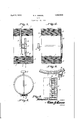
In describing the invention in detail, reference will be had to the accompanying drawings wherein like characters denote like or corresponding parts throughout the several views, and in which Figure 1 is an elevation showing one manner of carrying out the invention.
Figure 2 is a view taken at right angles to Figure 1.
Figure 3 is a top plan view.
Figure 4 is a section on line l l of Figure 1.
Figure 5 is a section on line 55 of Figure 1.
As shown in these views, each convolution of the coil A is formed continuous by a space 2 which supports the adjacent or meeting ends of the coil. A rack bar 3 has a part 4 adapted to move between the ends of the sections, and in order to permit the rack bar to connect all the sections of the coil together when desired, the spaces 2 are placed in alignment, as shown, and the adjacent ends of the sections of the convolutions are bent outwardly, as shown at 5, to receive the part 4 of the rack bar. The rack bar is formed of insulating material and conductors 6 are carried by the part 4 for bridging the spaces 2. Of course, these conductors 6 are spaced the same distance as are the convolutions of the coil so that by moving the rack bar into or from the row of spaces 2, any nimiber of the convolutions of the coil can have their sections eonnected together by the conductors 6. Thus I have provided simple means for adjusting the length of a coil while eliminating dead end losses, as those convolutions of the coil not in use are electrically disconnected from the convolutions which are in use.
The rack bar is adjusted through means of a pinion 7 on a shaft 8 which is provided with a handle 9 so that it can be turned in either direction to cause the pinion to move the rack bar in either direction. The drawings show a pair of these rack bars for adjusting the length of a pair of coils.
This invention may be used in any device or wherever it is desired to adjust the length of a coil or coils or the number of windings of the coils which are to be electrically connected together.
t is thought from the foregoing descripion that the advantages and novel features of the invention will be readily apparent.
t is to be understood that changes may be made in the construction and in the combination and arrangement of the several parts, provided that such changes fall within the scope of the appended claims.
What I claim is 1. A coil comprising a series of convolutions, each convolution having outwardly bent portions providing a space between and adjacent the ends thereof, and means for bridging the spaces of any desired number of convolutions.
2. A coil comprising a series of convolutions, each convolution having outwardly bent portions providing a space between and adjacent the ends thereof, means for bridging the spaces of any desired number of convolutions, said means comprising a rack bar, conductors carried by the rack bar and electrically connecting the adjacent ends of the convolutions together, a pinion meshing with the bar and a shaft for rotating the pinion.
3. A coil comprising a. series of convolutions, each convolution having outwardly bent portions providing a space between and adjacent the ends thereof, and slidable means for bridging the spaces of any desired number of convolutions.
4. A coil comprising a series of convolutions, each convolution having outwardly bent portions providing a space between and adjacent the ends thereof, and oppositely slidable means for bridging the spaces of any desired number of convolutions.
In testimonywhereof I affix my signature.
RICHARD. H. SAMUEL.
Priority Applications (1)
| Application Number | Priority Date | Filing Date | Title |
|---|---|---|---|
| US483690A US1852938A (en) | 1930-09-22 | 1930-09-22 | Coil |
Applications Claiming Priority (1)
| Application Number | Priority Date | Filing Date | Title |
|---|---|---|---|
| US483690A US1852938A (en) | 1930-09-22 | 1930-09-22 | Coil |
Publications (1)
| Publication Number | Publication Date |
|---|---|
| US1852938A true US1852938A (en) | 1932-04-05 |
Family
ID=23921124
Family Applications (1)
| Application Number | Title | Priority Date | Filing Date |
|---|---|---|---|
| US483690A Expired - Lifetime US1852938A (en) | 1930-09-22 | 1930-09-22 | Coil |
Country Status (1)
| Country | Link |
|---|---|
| US (1) | US1852938A (en) |
Cited By (1)
| Publication number | Priority date | Publication date | Assignee | Title |
|---|---|---|---|---|
| US2570311A (en) * | 1949-06-01 | 1951-10-09 | Union Carbide & Carbon Corp | Electric induction furnace |
-
1930
- 1930-09-22 US US483690A patent/US1852938A/en not_active Expired - Lifetime
Cited By (1)
| Publication number | Priority date | Publication date | Assignee | Title |
|---|---|---|---|---|
| US2570311A (en) * | 1949-06-01 | 1951-10-09 | Union Carbide & Carbon Corp | Electric induction furnace |
Similar Documents
| Publication | Publication Date | Title |
|---|---|---|
| GB817643A (en) | Improvements in or relating to spacer means for suspended lines | |
| US1852938A (en) | Coil | |
| US1662771A (en) | Resistance unit | |
| US1402889A (en) | Electric heating element | |
| US2138330A (en) | Radio frequency coil | |
| US1488873A (en) | Winding | |
| USRE22313E (en) | Electric resistor | |
| US1364967A (en) | Rheostat | |
| US1445919A (en) | Electrical coil unit | |
| GB1078919A (en) | Non-inductive wire configurations | |
| US1697600A (en) | Condensing coil | |
| US3976904A (en) | Transposed bar for electric machines | |
| US1776859A (en) | Binding post | |
| US1555292A (en) | Electric-furnace heating unit | |
| US2993186A (en) | Bobbin type electrical resistor | |
| DE1591440B1 (en) | Clamp plug for HF coaxial lines | |
| US848676A (en) | Electric transformer. | |
| US1552686A (en) | Electric resistance coils free from induction and capacity | |
| US2050221A (en) | Terminal for edgewise wound resistors | |
| DE477328C (en) | Constantly changing self-induction | |
| US1680415A (en) | Coil mounting | |
| US1542967A (en) | Electric heater | |
| US2050220A (en) | Terminal for edge wound resistors | |
| US747595A (en) | Coil for electrical machines. | |
| US751459A (en) | Line-insulator |