US1852934A - Toy whistle - Google Patents
Toy whistle Download PDFInfo
- Publication number
- US1852934A US1852934A US544241A US54424131A US1852934A US 1852934 A US1852934 A US 1852934A US 544241 A US544241 A US 544241A US 54424131 A US54424131 A US 54424131A US 1852934 A US1852934 A US 1852934A
- Authority
- US
- United States
- Prior art keywords
- section
- sections
- whistle
- line
- blank
- Prior art date
- Legal status (The legal status is an assumption and is not a legal conclusion. Google has not performed a legal analysis and makes no representation as to the accuracy of the status listed.)
- Expired - Lifetime
Links
- 230000015572 biosynthetic process Effects 0.000 description 5
- 238000010276 construction Methods 0.000 description 5
- 238000005755 formation reaction Methods 0.000 description 5
- 239000002184 metal Substances 0.000 description 4
- 101100396546 Neurospora crassa (strain ATCC 24698 / 74-OR23-1A / CBS 708.71 / DSM 1257 / FGSC 987) tif-6 gene Proteins 0.000 description 1
- 101150094640 Siae gene Proteins 0.000 description 1
- 239000004020 conductor Substances 0.000 description 1
- 238000004519 manufacturing process Methods 0.000 description 1
- 238000004088 simulation Methods 0.000 description 1
Images
Classifications
-
- G—PHYSICS
- G10—MUSICAL INSTRUMENTS; ACOUSTICS
- G10K—SOUND-PRODUCING DEVICES; METHODS OR DEVICES FOR PROTECTING AGAINST, OR FOR DAMPING, NOISE OR OTHER ACOUSTIC WAVES IN GENERAL; ACOUSTICS NOT OTHERWISE PROVIDED FOR
- G10K5/00—Whistles
Definitions
- Figure 10 The primary object ofthesinventionis to Figure 10 is a vertical long'itiidinalsecprovide a i toy whistle of extremely simple komal view taken on line 10;'-10 of Figure 9.; 5 construction,'inexpensive to manufacture'and i .
- Figure l1 is a lvertical longitudinal scwk easy to operate, the effects yproduced beingl tional view taken on line v11-11 of Figure 9;
- Figure 12 is a vertical longitudinal sec-
- Figure 13 is a cross-sectional view'taken 10 ter, preferably constructed'of sheet-metal on line 13-13.of Figure 12; y n
- oneiforni of construe- F igure 14 is a developed plan view of the tion being constructed of two parts con-iV single blank from whichjthe whistle con-V nected togetherw-hile the other forms of con-,- struction shown in Figures 9 to 13 is con-V struction embody yasingle blank adapted .to structed; y'15'beloentinto article or whistleforination; Figure 15 is atop planl view of .another @y 1 Withythe above and other objects4 in View. forni of toy whistle,
- Figure 16 isy a vertical longitudinal secthe invention is .better understood, the same tional view taken on linelG-l ofg Figure 15; consists in thenovelforno,y combination and Figure 17 is a vertical longitudinal .sec-
- V Figure ⁇ 18 is a vertical longitudinal ⁇ sec- In the drawings z-f Y tional View taken on line 18e-18 of Figure 15 f
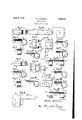
- Figure 1 is atop planview 1of a toy whistle
- Figure 19k is a kcross-sectional vievzif takeli constructed in accordance with .the presenty OIIBQIIQ 19-019 0f lglle l; lld f th 71% ⁇ invention.
- s s igure is ay eve ope pan View o Y e FigureQis a verticallongitudinalsectional.v Sllgleg blank from which the Whlstlj COD-L View taken 0n line 2 2 of Figure, 13.
- Figure V is a cross-sectional View7 taken stmcted ,A on une 3 3 of Figure 2y 111122,@ fflltthelnge@ Shomig a 4 *of gwgnbllerf ghsllgugdhlsde: and as shown in Figure 4,(one part comprises UQ g the blank havin@ sections 1,2 and 3 bendable Figure 551s a iop Plan Vlew of, amither uponthe dottedclinesit and 5, this part'being 802 1 qrm i Whl-Stl? toy 'Constructed of a Smgle of elongated rectangular form.
- the other P180? Ofmatflal' I Y part of the device comprises an intermediate Fleur? 6 '1S a vertical lonslfudlglal Sec Section 6 with Siae Sections 'randa-bie upon tional view taken-online tif-6 of Figure V5; th@ dotted lines g j y 0n 1in@ 17-"7'0f Figure-65 l i as shownfin Figures-1 to 43, thefsection is y Figure 8 S aideveloped Plant-View 0f the placed yupon the section y2 andthe :side secbl'ankfromwhich ⁇ the whistle shown in Fig# o tions 7 ⁇ arebent uponthe lines 48 to Vcause'the uresy 5 to '7 is'constructed; sections 7 vto be moved to positions beneath Figure 9 ⁇ is a top plan view of another the section .2.- Thewsection 3' is athen bent i upon the line 5 and moved into engagement with the underlying sections 7 as shown in
- the section 1 is then bent to provide an open loop or ring as shown in Figure 2 to occupy a position below the plane of the section 2 With the terminal end 1a of the section 1 in spaced relation to the adjacent end of the air passage or channel 9.
- air is blown through the passage 9 from the end thereof opposite the looped section 1 and fingers of the. user are adapted to close the open side of the looped section 1, movement of the fingers producing different whistle effects.
- the blank from which the Whistle is formed comprises an elongated portion comprising scctions l0 and 11 bendable upon the line 12.
- a part of the blank extends laterally of one side of the section 11 and includes sections 13 and 14 foldable respectively upon lines 15 and 16.
- the section 13 is bendable upon the line 15 to overlie the section 11 of the end section 14 of the side part is bendable upon the line 16 to underlie the section 11, the section 10 being then bent upon the line 12 into looped formation as shown in Figure 6 to occupy a position beneath the plane of the section 11 with the terminal end 10a of the section 10 spaced from the adjacent end of the air passage 17 formed between the sections 11 and 13, the Whistle being operated in a manner as described in connection With Figures 1 to 4.
- the Whistle is of duplicate construction and is formed from the single blank shown in Figure 14.
- the blank comprises an elongated rectangular portion comprising sections 18, 19 and 20 foldable upon lines 21 and 22 while a side section projecting laterally on one side of the section 18 includes sections 23 and an intermediate part comprising sections 24 and 25, the sections 23 and 24 being bendable upon the line 26 While the section 25 is bendable upon the line 27.
- the section 19 is bent upon the line 21 to overlie the section 18, While the end section 20 is bent upon the line 22 to underlie the section 18 and retain the sections 18 and 19 in position.
- the section 24 is then bent upon the line 26 to overlie the section 19 and the end section 25 is bent upon the line 27 to underlie the section 18 to retain the parts in position.
- those portions of the several sections 18.I 19 and 22 are moved into contacting relation to provide end air passages 28 between the outer ends of the sections 18 and 19 as illustrated.
- the sections 23 are then bent upon the lines 26 linto looped formation to occupy positions beneath the plane of the carrying section 18 with the terminal ends 23 thereof spaced from the adjacent ends of the air passages 28 as shown in Figure 10, the operation of this whistle being accomplished in a manner as described in connection with Figures 1 to 8, the whistle sections being separately operable.
- a sheet metal strip bent to provide overlying sections, a looped end disposed in a plane below the sections and a separate strap member overlying the upper section with its side edges confined between the overlying sections, and the intermediate portion of said strap member being spaced from the upper section to provide an air passage with the free end of the loop disposed adjacent one end of the air passage.
- a Whistle of the character described composed of a strip of metal of elongated rectangular form in plan and folded into three sections, one end section being formed into a loop terminating in an edge and the other end section folded under and parallel to the intermediate section and spaced therefrom, and a second strip composed of a sheet of metal of substantially rectangular form in plan and comprising a flat middle section with opposite end sections bent and folded and embracing the intermediate section of the first named strip, and inter-looked between saidintermediate section of the first named strip,l Vand the vunder folded section yof the first named strip, an air conductor.
Landscapes
- Physics & Mathematics (AREA)
- Engineering & Computer Science (AREA)
- Acoustics & Sound (AREA)
- Multimedia (AREA)
- Toys (AREA)
Description
i Aprils, 1932. w M|CHAL5K| Y 1,852,934
TOY WHISTLE Filed June 13, 1931 arrangement of parts hereinafter more fully tional ,view'taken on line'17-l7 lof Fig'- i "m Figur@ 7 is a `C1`0S-S'Secti0na1 View taken ln'assernbling the two parts of `the device u yPatented Apu-5, 1932. p g s l i UNITED@"STArssi nare-Nr# WALTER ntrcnnnsm,@or nnooxnvnnnw YoRK;
i froY WHISTLE 4Applmation inea :rune 13, 1931.* serial No.v 544,241.
us'efulimproveinent's in;` toy Whistles. v y whistle sections; s
kThe primary object ofthesinventionis to Figure 10 is a vertical long'itiidinalsecprovide a i toy whistle of extremely simple ktional view taken on line 10;'-10 of Figure 9.; 5 construction,'inexpensive to manufacture'and i .Figure l1 is a lvertical longitudinal scwk easy to operate, the effects yproduced beingl tional view taken on line v11-11 of Figure 9;
vThis invention relates to certain new and-y form of `toy whistle elnbodying duplicate in simulation of whistles or songs of birds. Figure 12 is a vertical longitudinal sec- A further object of the inventionizis to protional View taken on line 12-`l2 of Figure 9; vide avtoyfwhistle of the foregoing charac-v Figure 13 is a cross-sectional view'taken 10 ter, preferably constructed'of sheet-metal on line 13-13.of Figure 12; y n
suchastin or the like, oneiforni of construe- F igure 14 is a developed plan view of the tion being constructed of two parts con-iV single blank from whichjthe whistle con-V nected togetherw-hile the other forms of con-,- struction shown in Figures 9 to 13 is con-V struction embody yasingle blank adapted .to structed; y'15'beloentinto article or whistleforination; Figure 15 is atop planl view of .another @y 1 Withythe above and other objects4 in View. forni of toy whistle,
that Ywill. become apparent asvthe nature 4of Figure 16 isy a vertical longitudinal secthe invention is .better understood, the same tional view taken on linelG-l ofgFigure 15; consists in thenovelforno,y combination and Figure 17 is a vertical longitudinal .sec-
described, showninthe accompanying ldrawfure 15;y s s ings and claimed. V Figure `18: is a vertical longitudinal `sec- In the drawings z-f Y tional View taken on line 18e-18 of Figure 15 f Figure 1 is atop planview 1of a toy whistle `Figure 19k is a kcross-sectional vievzif takeli constructed in accordance with .the presenty OIIBQIIQ 19-019 0f lglle l; lld f th 71%` invention. s s igure is ay eve ope pan View o Y e FigureQis a verticallongitudinalsectional.v Sllgleg blank from which the Whlstlj COD-L View taken 0n line 2 2 of Figure, 13. structlon shown ln 4Figuresl to 1191s con-V Figure V is a cross-sectional View7 taken stmcted ,A on une 3 3 of Figure 2y 111122,@ fflltthelnge@ Shomig a 4 *of gwgnbllerf ghsllgugdhlsde: and as shown in Figure 4,(one part comprises UQ g the blank havin@ sections 1,2 and 3 bendable Figure 551s a iop Plan Vlew of, amither uponthe dottedclinesit and 5, this part'being 802 1 qrm i Whl-Stl? toy 'Constructed of a Smgle of elongated rectangular form. The other P180? Ofmatflal' I Y part of the device comprises an intermediate Fleur? 6 '1S a vertical lonslfudlglal Sec Section 6 with Siae Sections 'randa-bie upon tional view taken-online tif-6 of Figure V5; th@ dotted lines g j y 0n 1in@ 17-"7'0f Figure-65 l i as shownfin Figures-1 to 43, thefsection is y Figure 8 S aideveloped Plant-View 0f the placed yupon the section y2 andthe :side secbl'ankfromwhich `the whistle shown in Fig# o tions 7 `arebent uponthe lines 48 to Vcause'the uresy 5 to '7 is'constructed; sections 7 vto be moved to positions beneath Figure 9` is a top plan view of another the section .2.- Thewsection 3' is athen bent i upon the line 5 and moved into engagement with the underlying sections 7 as shown in Figure 3 and cooperates with the section 2 to form ay clamp for the sections 7, the fold lines 8 being of a character to provide an air space or channel 9 between the sections 6 and 2. The section 1 is then bent to provide an open loop or ring as shown in Figure 2 to occupy a position below the plane of the section 2 With the terminal end 1a of the section 1 in spaced relation to the adjacent end of the air passage or channel 9. To operate the Whistle, air is blown through the passage 9 from the end thereof opposite the looped section 1 and fingers of the. user are adapted to close the open side of the looped section 1, movement of the fingers producing different whistle effects.
In the form of the invention shown in Figures 5 to 8 and as shown in Figure 8, the blank from which the Whistle is formed comprises an elongated portion comprising scctions l0 and 11 bendable upon the line 12. A part of the blank extends laterally of one side of the section 11 and includes sections 13 and 14 foldable respectively upon lines 15 and 16.
To move the blank shown in Figure 8 into Whistle formation shown in Figures 5 to 7, the section 13 is bendable upon the line 15 to overlie the section 11 of the end section 14 of the side part is bendable upon the line 16 to underlie the section 11, the section 10 being then bent upon the line 12 into looped formation as shown in Figure 6 to occupy a position beneath the plane of the section 11 with the terminal end 10a of the section 10 spaced from the adjacent end of the air passage 17 formed between the sections 11 and 13, the Whistle being operated in a manner as described in connection With Figures 1 to 4.
In the form of the invention shown in Figures 9 to 14, the Whistle is of duplicate construction and is formed from the single blank shown in Figure 14. The blank comprises an elongated rectangular portion comprising sections 18, 19 and 20 foldable upon lines 21 and 22 while a side section projecting laterally on one side of the section 18 includes sections 23 and an intermediate part comprising sections 24 and 25, the sections 23 and 24 being bendable upon the line 26 While the section 25 is bendable upon the line 27. To move t-he blank shown in Figure 14 into whistle formation as shown in Figures 9 to 13, the section 19 is bent upon the line 21 to overlie the section 18, While the end section 20 is bent upon the line 22 to underlie the section 18 and retain the sections 18 and 19 in position. The section 24 is then bent upon the line 26 to overlie the section 19 and the end section 25 is bent upon the line 27 to underlie the section 18 to retain the parts in position. As shown in Figure 13, those portions of the several sections 18.I 19 and 22 are moved into contacting relation to provide end air passages 28 between the outer ends of the sections 18 and 19 as illustrated. The sections 23 are then bent upon the lines 26 linto looped formation to occupy positions beneath the plane of the carrying section 18 with the terminal ends 23 thereof spaced from the adjacent ends of the air passages 28 as shown in Figure 10, the operation of this whistle being accomplished in a manner as described in connection with Figures 1 to 8, the whistle sections being separately operable.
In the form of the invention illust-rated in Figures 15 to 20, the same is of duplicate Whistle construction as illustrated in Figures 9 to 14 and is of similar construction thereto, embodying like sections designated by similar numerals with the exception that the end section 20a of the elongated rectangular portion of the blank as shown in Figure 20 and the section 25a of the intermediate portion between the sections 23 are of increased len h as will be understood from the comparison of Figures 14 and 20. The blank shown in Figure 20 is bent and folded as described in connection with Figure 14 to assume formations illustrated in Figures 15 to 19, the section 20a extending a. greater distance over the section 18 and engaged by one side of the section 25a to retain the section 25a in position as Well as the overlapping sections of the blank.
From the above detailed description of the invention, it is believed that the construction and use thereof will at once be apparent and While there are herein shown and described the preferred embodiments of the invention, it is nevertheless to be understood that minor changes may be made therein Without departing from the spirit and scope of the invention as claimed.
I claim 1. In a toy Whistle of the character described, a sheet metal strip bent to provide overlying sections, a looped end disposed in a plane below the sections and a separate strap member overlying the upper section with its side edges confined between the overlying sections, and the intermediate portion of said strap member being spaced from the upper section to provide an air passage with the free end of the loop disposed adjacent one end of the air passage.
2. A Whistle of the character described, composed of a strip of metal of elongated rectangular form in plan and folded into three sections, one end section being formed into a loop terminating in an edge and the other end section folded under and parallel to the intermediate section and spaced therefrom, and a second strip composed of a sheet of metal of substantially rectangular form in plan and comprising a flat middle section with opposite end sections bent and folded and embracing the intermediate section of the first named strip, and inter-looked between saidintermediate section of the first named strip,l Vand the vunder folded section yof the first named strip, an air conductor.
space being left between Ithe intermediate section of the first named strip and the rlet mid-` dle' portion of the second strip, said space terminating opposite and spaced from the opposing edge of the loop, Wherebythe air projected through-said air space, will strike and vibrate the edge of the loop,y said loop being Vopen at both sides. Y
In testimony whereof I aix my signature.
WALTER MCHALSKI.
Priority Applications (1)
| Application Number | Priority Date | Filing Date | Title |
|---|---|---|---|
| US544241A US1852934A (en) | 1931-06-13 | 1931-06-13 | Toy whistle |
Applications Claiming Priority (1)
| Application Number | Priority Date | Filing Date | Title |
|---|---|---|---|
| US544241A US1852934A (en) | 1931-06-13 | 1931-06-13 | Toy whistle |
Publications (1)
| Publication Number | Publication Date |
|---|---|
| US1852934A true US1852934A (en) | 1932-04-05 |
Family
ID=24171358
Family Applications (1)
| Application Number | Title | Priority Date | Filing Date |
|---|---|---|---|
| US544241A Expired - Lifetime US1852934A (en) | 1931-06-13 | 1931-06-13 | Toy whistle |
Country Status (1)
| Country | Link |
|---|---|
| US (1) | US1852934A (en) |
Cited By (4)
| Publication number | Priority date | Publication date | Assignee | Title |
|---|---|---|---|---|
| US4821670A (en) * | 1987-08-07 | 1989-04-18 | Fortron Inc. | Whistle |
| US5251569A (en) * | 1991-11-04 | 1993-10-12 | Seron Manufacturing Co. | Multiple tone whistle |
| FR2770673A1 (en) * | 1997-11-03 | 1999-05-07 | Christian Laurent | Two-tone whistle |
| WO2012084875A1 (en) * | 2010-12-21 | 2012-06-28 | Hoeflinger Andreas | Beverage can containing a sound generator |
-
1931
- 1931-06-13 US US544241A patent/US1852934A/en not_active Expired - Lifetime
Cited By (4)
| Publication number | Priority date | Publication date | Assignee | Title |
|---|---|---|---|---|
| US4821670A (en) * | 1987-08-07 | 1989-04-18 | Fortron Inc. | Whistle |
| US5251569A (en) * | 1991-11-04 | 1993-10-12 | Seron Manufacturing Co. | Multiple tone whistle |
| FR2770673A1 (en) * | 1997-11-03 | 1999-05-07 | Christian Laurent | Two-tone whistle |
| WO2012084875A1 (en) * | 2010-12-21 | 2012-06-28 | Hoeflinger Andreas | Beverage can containing a sound generator |
Similar Documents
| Publication | Publication Date | Title |
|---|---|---|
| US1852934A (en) | Toy whistle | |
| Johnson | Keep Your Lamp Trimmed and Burning | |
| US2165901A (en) | Handbag structure | |
| US2057838A (en) | Necktie box | |
| US2205813A (en) | Sputum cup | |
| US1856164A (en) | Musical novelty | |
| US2091488A (en) | Barbecue | |
| USD86705S (en) | Design for a cover plate for musical instruments | |
| USD113643S (en) | Design for a manicure drier | |
| USD85541S (en) | Charles pecxerman | |
| USD71936S (en) | Design eor a combined peg head and heck eor a stringed musical | |
| USD71842S (en) | Design for a lamp-post | |
| USD109917S (en) | Design for an egg tester | |
| USD77311S (en) | Design for a cedar chest | |
| USD136881S (en) | Design for a smoking pipe | |
| USD107083S (en) | Design for a rug | |
| USD121142S (en) | Combined bracket and latch for hair driers | |
| USD107592S (en) | Design for a coin bank | |
| USD67885S (en) | Besign pob | |
| USD90845S (en) | Design for a chandelier | |
| USD80687S (en) | Design for a box | |
| USD81731S (en) | Herman schlacht | |
| USD81053S (en) | Design for an incinerator | |
| USD72433S (en) | Design for a stringed musical instrument | |
| USD85551S (en) | Design fob a chair |