US1852924A - Mechanical stop for bottle capping machines - Google Patents
Mechanical stop for bottle capping machines Download PDFInfo
- Publication number
- US1852924A US1852924A US453800A US45380030A US1852924A US 1852924 A US1852924 A US 1852924A US 453800 A US453800 A US 453800A US 45380030 A US45380030 A US 45380030A US 1852924 A US1852924 A US 1852924A
- Authority
- US
- United States
- Prior art keywords
- bottle
- head
- lever
- machine
- sleeve
- Prior art date
- Legal status (The legal status is an assumption and is not a legal conclusion. Google has not performed a legal analysis and makes no representation as to the accuracy of the status listed.)
- Expired - Lifetime
Links
- 210000003739 neck Anatomy 0.000 description 12
- 230000003534 oscillatory effect Effects 0.000 description 8
- 241000282472 Canis lupus familiaris Species 0.000 description 5
- HEMHJVSKTPXQMS-UHFFFAOYSA-M Sodium hydroxide Chemical compound [OH-].[Na+] HEMHJVSKTPXQMS-UHFFFAOYSA-M 0.000 description 1
- 238000010276 construction Methods 0.000 description 1
- 210000002445 nipple Anatomy 0.000 description 1
Images

Classifications
-
- B—PERFORMING OPERATIONS; TRANSPORTING
- B67—OPENING, CLOSING OR CLEANING BOTTLES, JARS OR SIMILAR CONTAINERS; LIQUID HANDLING
- B67B—APPLYING CLOSURE MEMBERS TO BOTTLES JARS, OR SIMILAR CONTAINERS; OPENING CLOSED CONTAINERS
- B67B3/00—Closing bottles, jars or similar containers by applying caps
- B67B3/02—Closing bottles, jars or similar containers by applying caps by applying flanged caps, e.g. crown caps, and securing by deformation of flanges
Definitions
- This invention relates to improvements in bottle capping machines and has for anob ject' the provision of means for automatically stopping the operation'ofthe 'machine in the event of failure to cap a bottle, the present application-being a companion case to application'Serial No. 284,619, filed June The application; referred to discloses,
- Figure 1' is a perspective view showing a fragmentary portion of a bottle capping ma
- Figure 3 is a' bottom plan-view ofthesubject matter of Figure 2. 7
- Figure 4 is a section on-the line44 of Figure 2..
- Figure 5 is a plan view of the clutch lever carried member.
- the machine as thus far described is of a type in common use and formsnopartof the invention, except that the magazine ,1 head is utilized for the support of the invention, while the movement of the head is utilized in '55' its operation.
- a bracket 14 With this in view, there is attached to the magazine head as'shownat 13, a bracket 14.
- This bracket carries spaced capping units, each of which includes cylin- 6" being equal to the spacing of'the bottles as
- the cylindrical members are closed at their inner ends andare attached to the bracket 14 by any suitable means indicated at 16.
- Movable within'the cylindrical member v15 is a plunger 17, whichisyyieldingly held against inward movement :by a spring 18.
- One end of this spring is seated within a socket 19 provided in the plunger, while its opposite end bears against thescrew 16,01
- a sleeve 20 Slidable upon the cylinder '15, is a sleeve 20 and this sleeve carries an outwardly ex. tending arm 21,.the arms of the sleeves of the 15 adjacent units extending inward ortoward' one another. Movement of the sleeve upon the cylinder 15 is limited by meansof-a. stop screw 22 whichis carried by the'cylinder and which extends through a slot 23 provided inthe-sleeve. The sleeve is yieldinglyheld inraised :position and in engagement with the bracket 14, by means of aspring 24.
- This fiangeor collar Surrounding the plunger 17 is afiange or 001131I25- This fiangeor collar isnotched as a at 26 and pivotally mounted within "this notch upon a pivot .pin27 is alatching dog 28.
- This dog has its bill vnormally forced outward by means of a'spring pressed;plung+ er '29, anduthis' bill is; adapted to engage a shoulder 30,'which surrounds the .inner'endi gaged by the dog 28, the sleeve will be held in] its lowermost position;
- plunger 17 is a provided with a seat 32 for engagement by the mouth of the bottle while (intending from this seat is an outwardly flared inclined flange 33 which guides the mouth of the bottle with- 5 in the seat.
- the head 31 is socket-ed as shown at 34 to receive the lower end of the plunger 17, while a headed screw or stud which is carried by this plunger extends througl'i and beyond the seat Movement of the head 31 in an upward direction is limited by the collar 25, while movement in an opposite direction is limited by the head of the screw 35. Upward movement of the cappng head is yieldingly resisted by a spring 36 which surrounds the screw 35.
- a rod 37 Guided in the bracket 14 and arranged in the path of upward movement of either of the arms 21 of the capping units is a rod 37. Upward movement of the rod is limited by a head 38 which engages the lower end of a guide nipple 39. The red 3? normally ositioned as shown by the dotted lines in i ure 2 so that the upper end of this rod is disposed only slightly above the upper face of the bracket 14.
- the outer end of this arm carries a hook 42, while its inner end is rigid with a sleeve 43.
- This sleeve is swiveled upon a spool 44 which is adjustably mounted upon the lever 40 by means of set screws 45.
- the sleeve 43 is thus swiveled upon the lever 40 and is rotatable upon said lever, rotary movement being limited by a pin 46 wl. c carried by the sleeve and which engages spaced shoulders 47 provided in the spool 44.
- a torsion spring 48 acts to yicldingly hold the pin against one of the shoulders as shown in Figure 5 of the drawings.
- the bottle neck engaging units are arranged-as shown at the right of Figure 2 of the drawings, with the sleeves 20 in their lowermost positions and held in such positions by the dogs 28.
- the rod 37 will then rest upon the arms 21 and will be in the posi tion shown by the dotted lines in Figure 2. 'ith the parts in this position, vertical and oscillatory movement of the head will occur during the operation of the capping machine without the rod engaging the hoot: 42.
- the arm 41 being mounted on the lever 40 for a limited yieldable movement is to permit said arm 41 to swing a distance sufficient for the passing of the rod 37 so that the latter may engage the hook during the oscillating movement of the magazine head when a bottle fails to receive a cap.
- the capped bottles will enter the head and when the vertically movable machine head descends, the head of the screw will engage the cap of the bottle and will force the cap into position upon the bottle. This operation will be repeated until one of the bottles fails to receive its cap.
- a vertically movable oscillatory head and means to feed bottles past the head for capping means including a lever to control the operation of the machine, and means operable when an uncapped bottle passes the head to actuate the lever and stop the operation of the machine automatically.
- a vertically movable oscillatory head and means to feed bottles past the head for capping means including a lever to control the operation of the machine, spaced bottle neck engaging units arranged in the path of the bottles after the latter receive caps, and means operated by either of the units and controlled by an uncapped bottle to actuate the lever and stop the machine automatically.
- a vertically movable oscillatory head and means to feed bottles past the head for capping means including a lever to control the operation of: the machine, a bottle neck engaging unit arranged in the path of the bottles after the latter receive caps, and means operable by said unit and controlled by an uncapped bottle to actuate the lever and stop the machine automatically.
- a vertically movable oscillatory head means to feed the bottles past the head to receive caps, a bottle neck engaging unit arranged in the path of the bottles after the later receive caps, means including a lever to control the operation of the magazine, a lever carried memher, and normally inactive means'movable into position to engage the lever and stop the machine automatically when the bottle neck engaging unit engages an uncapped bottle.
- a vertically movable oscillatory head means to feed the bottles past the head to receive caps, a
- bottle neck engaging unit arranged in the path of the bottles after the latter to receive caps, means including a lever to control the operation of the magazine, a lever carried member, a vertically movable rod, and means carried by the bottle neck engaging unit to move the rod into position to engage the lever carried member and stop the machine automatically when the bottle neck engaging unit engages an uncapped bottle.
- a vertically movable oscillatory head means to feed the bottles past the head to receive caps, a bottle neck engaging unit arranged in the. path of the bottles after the latter receive caps, said unit including a cylinder, a-spring influenced plunger extending from the cylinder, a spring influenced sleeve slidable upon the cylinder, a lever for controlling the ma- 7 chine, a vertically movable rod, an armcarried by the sleeve to engage the :rod and move the latter into position to engage the lever to actuate said lever and stop the machine automatically, means to hold the sleeve against inward movement, and means actuated by contact with an uncapped bottle to release the sleeve holding means.
- a vertically movable oscillatory head means to feed the bottles past the head to receive caps
- a bottle neck engaging unit arranged in the path of the bottles after the latter receive caps, said unit including a cylinder, a spring influenced plunger extending from the cylinder, a
- sleeve slidable upon the cylinder
- a lever for controlling the machine a vertically movable rod
- a plunger carried spring influenced latch normally engaging the sleeve to hold the latter against upward movement, and means actuated by contact with an uncapped bottle to actuate the latch and release the sleeve.
Landscapes
- Engineering & Computer Science (AREA)
- Mechanical Engineering (AREA)
- Sealing Of Jars (AREA)
Description
. April 1932- F. E. FOWLER 1,352,924
MECHANICAL STOP FOR BOTTLE CAPPING MACHINES Filed May 19, 1930 2 Sheets-Sheet l 7 Exam? 15'? FEW/e2" INVENTOR ATTORNEY A ril 5, 1932. F WL R 1,852,924
MECHANICAL STOP F'OR BOTTLE CAPPING MACHINES Filed May 19, 1930 2 Sheets-Sheet 2 Fran? i. FEM/e2 INVENTOR ATTORNEY Patented Apr. 5, .1932.
UNITED ,srAr s.
FRANK rownmt, or ArHENs,-GEoRGIAf MECHANICAL .STOP FOR BOTTLE GAPPING MACHINES Application filed May .19, 1920. Serial No. 453,800. I
This inventionrelates to improvements in bottle capping machines and has for anob ject' the provision of means for automatically stopping the operation'ofthe 'machine in the event of failure to cap a bottle, the present application-being a companion case to application'Serial No. 284,619, filed June The application; referred to discloses,
means .for automatically interrupting an electric circuit to. stop the operation of the capping machine in the event of failure to cap, a bottle, while the present application provides meansfor throwing out the.clutch which'controls the operation of the machine, so that the machine is stopped without stopping'the motor when the machine fails from any cause to'cap a; bottle. 8
With the above and otherobjects in :view,
,. the invention further includesthe'following novel features and details of constructiom to be hereinafter more fully described, illustrated inthe accompanying drawings and pointed out in the appended claims.
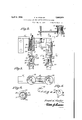
In the drawings n Figure 1' is a perspective view showing a fragmentary portion of a bottle capping ma;
chine with the invention applied. I
-Figure 2 is anelevation partly'm section of the invention per se.
' Figure 3 is a' bottom plan-view ofthesubject matter of Figure 2. 7
Figure 4 is a section on-the line44 of Figure 2.. p
Figure 5 is a plan view of the clutch lever carried member.
ceives the necks of the bottles which are i moved into position by means of a feed de' vice indicated at 11 and guided by means of a guide-12. Thebottles :B are in position for capping, while the bottlesb'have passed this positionand have already been capped,
bottle neck engaging head '31. This head *is.
while the bottle 72 remains uncapped.
and the opposite end is attached to the cylin- 8 ,of the sleeve-20. When the shoulder ,is en-:
The machine as thus far described is of a type in common use and formsnopartof the invention, except that the magazine ,1 head is utilized for the support of the invention, while the movement of the head is utilized in '55' its operation. With this in view, there is attached to the magazine head as'shownat 13, a bracket 14. This bracket carries spaced capping units, each of which includes cylin- 6" being equal to the spacing of'the bottles as The cylindrical members are closed at their inner ends andare attached to the bracket 14 by any suitable means indicated at 16.
Movable within'the cylindrical member v15 is a plunger 17, whichisyyieldingly held against inward movement :by a spring 18. One end of this spring is seated within a socket 19 provided in the plunger, while its opposite end bears against thescrew 16,01
against the "inner end of the cylinder.
' Slidable upon the cylinder '15, is a sleeve 20 and this sleeve carries an outwardly ex. tending arm 21,.the arms of the sleeves of the 15 adjacent units extending inward ortoward' one another. Movement of the sleeve upon the cylinder 15 is limited by meansof-a. stop screw 22 whichis carried by the'cylinder and which extends through a slot 23 provided inthe-sleeve. The sleeve is yieldinglyheld inraised :position and in engagement with the bracket 14, by means of aspring 24. One
end of ,thisspring is attached to the'sleeve der.
Surrounding the plunger 17 is afiange or 001131I25- This fiangeor collar isnotched as a at 26 and pivotally mounted within "this notch upon a pivot .pin27 is alatching dog 28. This dog has its bill vnormally forced outward by means of a'spring pressed;plung+ er '29, anduthis' bill is; adapted to engage a shoulder 30,'which surrounds the .inner'endi gaged by the dog 28, the sleeve will be held in] its lowermost position;
Mounted for limited I sliding movement upon the lower end of the .plunger 17 is a provided with a seat 32 for engagement by the mouth of the bottle while (intending from this seat is an outwardly flared inclined flange 33 which guides the mouth of the bottle with- 5 in the seat. The head 31 is socket-ed as shown at 34 to receive the lower end of the plunger 17, while a headed screw or stud which is carried by this plunger extends througl'i and beyond the seat Movement of the head 31 in an upward direction is limited by the collar 25, while movement in an opposite direction is limited by the head of the screw 35. Upward movement of the cappng head is yieldingly resisted by a spring 36 which surrounds the screw 35.
Guided in the bracket 14 and arranged in the path of upward movement of either of the arms 21 of the capping units is a rod 37. Upward movement of the rod is limited by a head 38 which engages the lower end of a guide nipple 39. The red 3? normally ositioned as shown by the dotted lines in i ure 2 so that the upper end of this rod is disposed only slightly above the upper face of the bracket 14.
Extending from the usual clutch lever 4-0 which operates a clutch (not shown) to control the operation of the machine, is an arn 41. The outer end of this arm carries a hook 42, while its inner end is rigid with a sleeve 43. This sleeve is swiveled upon a spool 44 which is adjustably mounted upon the lever 40 by means of set screws 45. The sleeve 43 is thus swiveled upon the lever 40 and is rotatable upon said lever, rotary movement being limited by a pin 46 wl. c carried by the sleeve and which engages spaced shoulders 47 provided in the spool 44. A torsion spring 48 acts to yicldingly hold the pin against one of the shoulders as shown in Figure 5 of the drawings. Normally, the bottle neck engaging units are arranged-as shown at the right of Figure 2 of the drawings, with the sleeves 20 in their lowermost positions and held in such positions by the dogs 28. The rod 37 will then rest upon the arms 21 and will be in the posi tion shown by the dotted lines in Figure 2. 'ith the parts in this position, vertical and oscillatory movement of the head will occur during the operation of the capping machine without the rod engaging the hoot: 42. Should one of the bottles, for example the bottle b, fail to receive a cap, the mouth of the bottle will engage the seat and when the vertically movable head descends, the head 31 will be forced upward. This lead is provided with an inclined top 49 which enga es the lower inclined end of the latching 0g 28 and moves this end of the dog ivotally outward to release the sleeve 20. his sleeve, under the action oi? the spring 24 will move upward and will carry the rod 37 upward so that when the head moves 1 horizontally to the left. the rod will engage the hook 42 and move the lever 40 to disengage the clutch. This position of the parts is illustrated at the left in Figure 2 of the drawings. The arm 41 being mounted on the lever 40 for a limited yieldable movement is to permit said arm 41 to swing a distance sufficient for the passing of the rod 37 so that the latter may engage the hook during the oscillating movement of the magazine head when a bottle fails to receive a cap.
The capped bottles will enter the head and when the vertically movable machine head descends, the head of the screw will engage the cap of the bottle and will force the cap into position upon the bottle. This operation will be repeated until one of the bottles fails to receive its cap.
lVhile the invention is shown as applied to a specific type of machine, it is not the purpose of the present application to restrict the invention in this particular, as it may, with minor changes, be applied to other types of bottle capping machines.
The invention is susceptible of various changes in its form, proportions and minor details of construction and the rightis herein reserved to make such changes as properly fall within the scope of the appended claims.
Having described the invention what is claimed is 1. In a bottle capping machine, a vertically movable oscillatory head and means to feed bottles past the head for capping, means including a lever to control the operation of the machine, and means operable when an uncapped bottle passes the head to actuate the lever and stop the operation of the machine automatically.
2. In a bottle capping machine, a vertically movable oscillatory head and means to feed bottles past the head for capping, means including a lever to control the operation of the machine, spaced bottle neck engaging units arranged in the path of the bottles after the latter receive caps, and means operated by either of the units and controlled by an uncapped bottle to actuate the lever and stop the machine automatically.
3. In a bottle capping machine, a vertically movable oscillatory head and means to feed bottles past the head for capping, means including a lever to control the operation of: the machine, a bottle neck engaging unit arranged in the path of the bottles after the latter receive caps, and means operable by said unit and controlled by an uncapped bottle to actuate the lever and stop the machine automatically.
4. In a bottle capping machine, a vertically movable oscillatory head, means to feed the bottles past the head to receive caps, a bottle neck engaging unit arranged in the path of the bottles after the later receive caps, means including a lever to control the operation of the magazine, a lever carried memher, and normally inactive means'movable into position to engage the lever and stop the machine automatically when the bottle neck engaging unit engages an uncapped bottle.
5. In a bottle capping machine, a vertically movable oscillatory head, means to feed the bottles past the head to receive caps, a
, bottle neck engaging unit arranged in the path of the bottles after the latter to receive caps, means including a lever to control the operation of the magazine, a lever carried member, a vertically movable rod, and means carried by the bottle neck engaging unit to move the rod into position to engage the lever carried member and stop the machine automatically when the bottle neck engaging unit engages an uncapped bottle.
6. In a bottle capping machine, a vertically movable oscillatory head, means to feed the bottles past the head to receive caps, a bottle neck engaging unit arranged in the. path of the bottles after the latter receive caps, said unit including a cylinder, a-spring influenced plunger extending from the cylinder, a spring influenced sleeve slidable upon the cylinder, a lever for controlling the ma- 7 chine, a vertically movable rod, an armcarried by the sleeve to engage the :rod and move the latter into position to engage the lever to actuate said lever and stop the machine automatically, means to hold the sleeve against inward movement, and means actuated by contact with an uncapped bottle to release the sleeve holding means.
7. In a bottle capping machine, a vertically movable oscillatory head, means to feed the bottles past the head to receive caps, a bottle neck engaging unit arranged in the path of the bottles after the latter receive caps, said unit including a cylinder, a spring influenced plunger extending from the cylinder, a
spring influenced sleeve slidable upon the cylinder, a lever for controlling the machine, a vertically movable rod, an arm carried by the sleeve to engage the rod and move the latter into position to engage the lever to actuate said lever and stop the machine automatical- I ly, a plunger carried spring influenced latch normally engaging the sleeve to hold the latter against upward movement, and means actuated by contact with an uncapped bottle to actuate the latch and release the sleeve.
In testimony whereof I affix my signature.
FRANK E. FOWLER.
Priority Applications (1)
| Application Number | Priority Date | Filing Date | Title |
|---|---|---|---|
| US453800A US1852924A (en) | 1930-05-19 | 1930-05-19 | Mechanical stop for bottle capping machines |
Applications Claiming Priority (1)
| Application Number | Priority Date | Filing Date | Title |
|---|---|---|---|
| US453800A US1852924A (en) | 1930-05-19 | 1930-05-19 | Mechanical stop for bottle capping machines |
Publications (1)
| Publication Number | Publication Date |
|---|---|
| US1852924A true US1852924A (en) | 1932-04-05 |
Family
ID=23802124
Family Applications (1)
| Application Number | Title | Priority Date | Filing Date |
|---|---|---|---|
| US453800A Expired - Lifetime US1852924A (en) | 1930-05-19 | 1930-05-19 | Mechanical stop for bottle capping machines |
Country Status (1)
| Country | Link |
|---|---|
| US (1) | US1852924A (en) |
Cited By (6)
| Publication number | Priority date | Publication date | Assignee | Title |
|---|---|---|---|---|
| US2579404A (en) * | 1948-11-15 | 1951-12-18 | George M Stevenson | Detector mechanism for capping machines |
| US2632553A (en) * | 1949-01-12 | 1953-03-24 | American Cyanamid Co | Container feeding machine |
| US2711821A (en) * | 1949-12-21 | 1955-06-28 | American Can Co | Container closure detector and throwout mechanism |
| US2922504A (en) * | 1956-02-01 | 1960-01-26 | Redington Co F B | Detector mechanism |
| US3186141A (en) * | 1961-06-01 | 1965-06-01 | Melikian Inc Rudd | Apparatus for production of tapes having spaced package pockets |
| CN106495072A (en) * | 2017-01-04 | 2017-03-15 | 安徽龙瑞玻璃有限公司 | The error-correction structure of simple cover locking machine |
-
1930
- 1930-05-19 US US453800A patent/US1852924A/en not_active Expired - Lifetime
Cited By (7)
| Publication number | Priority date | Publication date | Assignee | Title |
|---|---|---|---|---|
| US2579404A (en) * | 1948-11-15 | 1951-12-18 | George M Stevenson | Detector mechanism for capping machines |
| US2632553A (en) * | 1949-01-12 | 1953-03-24 | American Cyanamid Co | Container feeding machine |
| US2711821A (en) * | 1949-12-21 | 1955-06-28 | American Can Co | Container closure detector and throwout mechanism |
| US2922504A (en) * | 1956-02-01 | 1960-01-26 | Redington Co F B | Detector mechanism |
| US3186141A (en) * | 1961-06-01 | 1965-06-01 | Melikian Inc Rudd | Apparatus for production of tapes having spaced package pockets |
| CN106495072A (en) * | 2017-01-04 | 2017-03-15 | 安徽龙瑞玻璃有限公司 | The error-correction structure of simple cover locking machine |
| CN106495072B (en) * | 2017-01-04 | 2018-10-23 | 安徽龙瑞玻璃有限公司 | The error-correction structure of simple cover locking machine |
Similar Documents
| Publication | Publication Date | Title |
|---|---|---|
| US1852924A (en) | Mechanical stop for bottle capping machines | |
| US2198225A (en) | Closure applying machine | |
| US2507072A (en) | Machine for applying gaskets to glass jars or like articles | |
| DE363550C (en) | Device for the aseptic filling of sterile liquids | |
| NO115456B (en) | ||
| US1779683A (en) | Adjustable positioning mechanism for bottle cappers | |
| US1772540A (en) | Stop for bottle-crowning machines | |
| DE388258C (en) | Device for turning the bottles in relation to the labeling device in labeling machines | |
| US1805680A (en) | Safety-device for bottle cap crimping machines | |
| US1702261A (en) | Bottle-capping machine | |
| US560930A (en) | Appaeatds foe capping bottles | |
| US2049761A (en) | Bottle capping mechanism | |
| US1549676A (en) | Bottle-capping mechanism | |
| US2260349A (en) | Capping mechanism | |
| US1609326A (en) | Automatic interlocking drive clutch for can-making and other machines | |
| US1043286A (en) | Bottle-capping machine. | |
| US1640332A (en) | Device for applying caps to bottles | |
| US2769532A (en) | Control for mechanisms | |
| US1478356A (en) | Transfer mechanism | |
| US1071262A (en) | Bottle-capping machine. | |
| US1140832A (en) | Machine for applying crowns to bottles. | |
| US2349502A (en) | Bottle-cap reclaiming machine | |
| US1397617A (en) | Bottle-capping apparatus | |
| US828055A (en) | Machine for capping bottles. | |
| US1823366A (en) | Bottle capper |