US1852923A - Electric insect exterminator - Google Patents
Electric insect exterminator Download PDFInfo
- Publication number
- US1852923A US1852923A US564588A US56458831A US1852923A US 1852923 A US1852923 A US 1852923A US 564588 A US564588 A US 564588A US 56458831 A US56458831 A US 56458831A US 1852923 A US1852923 A US 1852923A
- Authority
- US
- United States
- Prior art keywords
- cylinder
- wires
- exterminator
- spaced
- insect
- Prior art date
- Legal status (The legal status is an assumption and is not a legal conclusion. Google has not performed a legal analysis and makes no representation as to the accuracy of the status listed.)
- Expired - Lifetime
Links
- 241000238631 Hexapoda Species 0.000 title description 14
- 239000011521 glass Substances 0.000 description 11
- 239000004020 conductor Substances 0.000 description 7
- 241000255925 Diptera Species 0.000 description 6
- 241000257159 Musca domestica Species 0.000 description 2
- 230000006378 damage Effects 0.000 description 2
- 239000000463 material Substances 0.000 description 2
- 241001080526 Vertica Species 0.000 description 1
- 238000001816 cooling Methods 0.000 description 1
- 230000009193 crawling Effects 0.000 description 1
- 238000010586 diagram Methods 0.000 description 1
- 238000006073 displacement reaction Methods 0.000 description 1
- 230000005611 electricity Effects 0.000 description 1
- 230000006698 induction Effects 0.000 description 1
- 238000007689 inspection Methods 0.000 description 1
- 230000033001 locomotion Effects 0.000 description 1
- 239000000725 suspension Substances 0.000 description 1
Images

Classifications
-
- A—HUMAN NECESSITIES
- A01—AGRICULTURE; FORESTRY; ANIMAL HUSBANDRY; HUNTING; TRAPPING; FISHING
- A01M—CATCHING, TRAPPING OR SCARING OF ANIMALS; APPARATUS FOR THE DESTRUCTION OF NOXIOUS ANIMALS OR NOXIOUS PLANTS
- A01M1/00—Stationary means for catching or killing insects
- A01M1/20—Poisoning, narcotising, or burning insects
- A01M1/2005—Poisoning insects using bait stations
- A01M1/2011—Poisoning insects using bait stations for crawling insects
-
- A—HUMAN NECESSITIES
- A01—AGRICULTURE; FORESTRY; ANIMAL HUSBANDRY; HUNTING; TRAPPING; FISHING
- A01M—CATCHING, TRAPPING OR SCARING OF ANIMALS; APPARATUS FOR THE DESTRUCTION OF NOXIOUS ANIMALS OR NOXIOUS PLANTS
- A01M1/00—Stationary means for catching or killing insects
- A01M1/02—Stationary means for catching or killing insects with devices or substances, e.g. food, pheronones attracting the insects
- A01M1/04—Attracting insects by using illumination or colours
-
- A—HUMAN NECESSITIES
- A01—AGRICULTURE; FORESTRY; ANIMAL HUSBANDRY; HUNTING; TRAPPING; FISHING
- A01M—CATCHING, TRAPPING OR SCARING OF ANIMALS; APPARATUS FOR THE DESTRUCTION OF NOXIOUS ANIMALS OR NOXIOUS PLANTS
- A01M1/00—Stationary means for catching or killing insects
- A01M1/20—Poisoning, narcotising, or burning insects
- A01M1/2005—Poisoning insects using bait stations
- A01M1/2016—Poisoning insects using bait stations for flying insects
-
- A—HUMAN NECESSITIES
- A01—AGRICULTURE; FORESTRY; ANIMAL HUSBANDRY; HUNTING; TRAPPING; FISHING
- A01M—CATCHING, TRAPPING OR SCARING OF ANIMALS; APPARATUS FOR THE DESTRUCTION OF NOXIOUS ANIMALS OR NOXIOUS PLANTS
- A01M1/00—Stationary means for catching or killing insects
- A01M1/22—Killing insects by electric means
- A01M1/223—Killing insects by electric means by using electrocution
-
- A—HUMAN NECESSITIES
- A01—AGRICULTURE; FORESTRY; ANIMAL HUSBANDRY; HUNTING; TRAPPING; FISHING
- A01M—CATCHING, TRAPPING OR SCARING OF ANIMALS; APPARATUS FOR THE DESTRUCTION OF NOXIOUS ANIMALS OR NOXIOUS PLANTS
- A01M2200/00—Kind of animal
- A01M2200/01—Insects
- A01M2200/011—Crawling insects
-
- A—HUMAN NECESSITIES
- A01—AGRICULTURE; FORESTRY; ANIMAL HUSBANDRY; HUNTING; TRAPPING; FISHING
- A01M—CATCHING, TRAPPING OR SCARING OF ANIMALS; APPARATUS FOR THE DESTRUCTION OF NOXIOUS ANIMALS OR NOXIOUS PLANTS
- A01M2200/00—Kind of animal
- A01M2200/01—Insects
- A01M2200/012—Flying insects
Definitions
- ()ur present invention relates to electrical appliances and more particularly to the application of electricity to the destruction of flies, moths and other pestiferous insects, and
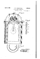
- Fig. 1 is a side elevation, partly in vertica section through the outer shell, of an exterminator constructed in accordance with and illustrating one embodiment of our invention
- Fig. 2 is a diagrammatic view of the circuit arrangements thereof
- Fig. 3 is a vertical central section through the device
- Fig. at is an enlarged fragmentary vertical section through the inner cylinder
- Fig. 5 is a fragmentary horizontal section through the cylinders on a reduced scale.
- flies such as the common house fly
- flies are attracted only in a general way by artificial light. They do not fly blindly toward it and against it with such aimless attraction as do moths and other night fiyers nor with the steady deliberation of mosquitoes, for instance.
- they do not seem to like unusual heat, so that with the ordinary exterminator of the general nature of the present one, but in which an incandescent bulb is simply placed behind bared high tension wires, they become diverted when they feel the heat emanating therefrom and are more apt to lightupon the guard or other adjacent surface.
- the exterminator shown is designed to be suspended from above and embodies a suspension hook 1 secured to the top of a dome or cap casing 2, the floor 3 of which is fastened to the cap by spacing and supporting bolts 4.
- a transformer housed within the casing 2 is a transformer, indicated generally at 5, for stepping up the ordinary 110 volt charge of alighting circuit to above the 2000 volts required to instantly destroy life.
- Beneath the center of the floor 3 is an incandescent lamp 6 in a socket-7 attached to the underside thereof.
- An outer flange 14 on the cap 2 is provided at intervals with fastening screws 15 that detachably support an outer glass cylinder 16.
- the upper rim of the cylinder abuts the floor 3 and is molded with the provision of a head 17 that rests on the screws 15.
- the cylinder 16 is a smaller concentrically arranged.
- inner glass cylinder 18 spaced therefrom and enclosing the lamp 6 from which it is also well spaced.
- This cylinder is also provided with a head 19 at its upper rim but on the inside and, by which it is detachably hung upon fastening screws 20 carried in brackets 21 de ending from the lower projecting ends of holts 4.
- Cylinder 18' preferably does not abut the floor 3, as does outer c linder 16, but is spaced therefrom by the rackets in order to allow circulation of air for ventilatin and cooling purposes. As will be seen, both cylinders are open at the bottom. from which point safe access may be had to the lamp or lure 6 with respect to the high tension circuit, the disposition of which will now be described.
- the conductors 12 and 13 are preferably in the form of flexible wires which are tightly wound in a double helix about the perimeter or outer surface of the inner cylinder 18, as clearly shown in Fig. In other words, their convolutions are parallel and alternated with each other so that adjacent parallel wires are of opposite polarity and can close the induced circuit 11 of the transformer when connected by the body of the insect ali htin upon or crawling upon the cylin er.
- the latter is preferably molded or blown with pairs of internal protuberances 24 disposed at intervals along the helical path of the wires 12 and 13 forming saddles in which they are locked against displacement.
- the flies enter the outer cylinder 16 from the bottom and instead of also entering the inner cylinder 18, they are repelled by the heat and proceed into the annular chamber between the cylinders, which is cooler as the material of the inner cylinder being glass is of low heat conductivity.
- the annular chamber Once in this annular chamber, even though they do not contact the high tension wires at once but crawl upon the inner surface of the outer cylinder, as soon as they start to buzz about, they are sure to strike the wires and their destruction ensues, the bodies falling out upon the ground.
- the dead bodies disengage t emselves readily and they are not so apt to cling to and foul the wires, as in the case of open wires arranged in cage-like form.
- the cylinders 16 and 18 as being made of glass which we prefer, equivalent materials may be substituted so long as they are dielectric and translucent.
- the lam 6 may be an ented as a lure with suita le bait attractive to flies or such bait substituted as a lure under some conditions.
Landscapes
- Life Sciences & Earth Sciences (AREA)
- Pest Control & Pesticides (AREA)
- Engineering & Computer Science (AREA)
- Insects & Arthropods (AREA)
- Wood Science & Technology (AREA)
- Zoology (AREA)
- Environmental Sciences (AREA)
- Health & Medical Sciences (AREA)
- General Health & Medical Sciences (AREA)
- Toxicology (AREA)
- Catching Or Destruction (AREA)
Description
April 5, 1932. w. F.' FOLMERET AL I ELECTRIC INSECT EXTERMINzfxTOR Fi led Sept. 23, 1951 2 Sheets-Sheet l 11v VENTORS mm WiZ71'a f/ar is TURNEY April 5, 1932. w. F. FOLMER ET AL ELECTRIC INSECT EXTERMINATOR Filed Sept. 23, 1951 2 Sheets-Sheet 2.
Pa ented Apr. .5, 1932 UNITED STATES PATENT oFFicr.
WILLIAM FOLHER AND HARRISON L. CHAIPIN, OF ROCHESTER, NEW YORK, AS- SIGNORS TO FOLMER-CHAPIN, CORPORATION, OF ROCHESTER, NEW YORK, A COR- PORATION F YORK ELECTRIC INSECT EXTERMINATOR Application filed September 23, 1931.
()ur present invention relates to electrical appliances and more particularly to the application of electricity to the destruction of flies, moths and other pestiferous insects, and
it has for its object to provide a simple, economical and efficient device of this character that will be of general utility but designed more particularly to fit the habits of and be effective against the common house fly.
To these and other ends, the invention resides in certain improvementsand combinations of parts, all as will be hereinafter more fully described, the novel features being pointed out in the claims at the end of the 16 specification.
In the drawings:
Fig. 1 is a side elevation, partly in vertica section through the outer shell, of an exterminator constructed in accordance with and illustrating one embodiment of our invention;
Fig. 2 is a diagrammatic view of the circuit arrangements thereof;
. Fig. 3 is a vertical central section through the device;
Fig. at is an enlarged fragmentary vertical section through the inner cylinder, and
Fig. 5 is a fragmentary horizontal section through the cylinders on a reduced scale.
Similar reference numerals throughout the several views indicate the same parts.
It is well known to those skilled in this particular art that flies, such as the common house fly, are attracted only in a general way by artificial light. They do not fly blindly toward it and against it with such aimless attraction as do moths and other night fiyers nor with the steady deliberation of mosquitoes, for instance. On the other hand, they do not seem to like unusual heat, so that with the ordinary exterminator of the general nature of the present one, but in which an incandescent bulb is simply placed behind bared high tension wires, they become diverted when they feel the heat emanating therefrom and are more apt to lightupon the guard or other adjacent surface.
It is further characteristic of the fly that its tendency is to fly or walk upwardly. Seldom will he proceed downwardly, as is borne Serial No. 564,583.
out by the common observation of the move ments of the fly upon a window pane.
In the practice of our present invention, we take these factors into consideration and provide a device open at the bottom and embodying inner and outer spaced shells of low heat conductivity, the inner shell containing a lamp, and the annular space between the shells constituting a relatively cool chamber, which the flies may enter from the bottom and explore but at least one wall of which is fitted with high tension conductors, contact with which is fatal to the insect.
Referring more particularly to the drawings, the exterminator shown is designed to be suspended from above and embodies a suspension hook 1 secured to the top of a dome or cap casing 2, the floor 3 of which is fastened to the cap by spacing and supporting bolts 4. Housed within the casing 2 is a transformer, indicated generally at 5, for stepping up the ordinary 110 volt charge of alighting circuit to above the 2000 volts required to instantly destroy life. Beneath the center of the floor 3 is an incandescent lamp 6 in a socket-7 attached to the underside thereof.
The circuit connections of these instrumentalities are readily understood from an inspection of F ig. 2, in which 8 and 9 are the line wires with the transformer field 10 and the lamp 6 in parallel therefrom. The high tension circuit from the induction field 11. leads through two conducting wires 12 and 13 having dead ends, as shown in diagram and which will be later referred to. The killing is effected by the body of the insect shorting these two conducting wires.
An outer flange 14 on the cap 2 is provided at intervals with fastening screws 15 that detachably support an outer glass cylinder 16. The upper rim of the cylinder abuts the floor 3 and is molded with the provision of a head 17 that rests on the screws 15. \Vithin the cylinder 16 is a smaller concentrically arranged. inner glass cylinder 18 spaced therefrom and enclosing the lamp 6 from which it is also well spaced. This cylinder is also provided with a head 19 at its upper rim but on the inside and, by which it is detachably hung upon fastening screws 20 carried in brackets 21 de ending from the lower projecting ends of holts 4. Cylinder 18'preferably does not abut the floor 3, as does outer c linder 16, but is spaced therefrom by the rackets in order to allow circulation of air for ventilatin and cooling purposes. As will be seen, both cylinders are open at the bottom. from which point safe access may be had to the lamp or lure 6 with respect to the high tension circuit, the disposition of which will now be described.
The conductors 12 and 13 are preferably in the form of flexible wires which are tightly wound in a double helix about the perimeter or outer surface of the inner cylinder 18, as clearly shown in Fig. In other words, their convolutions are parallel and alternated with each other so that adjacent parallel wires are of opposite polarity and can close the induced circuit 11 of the transformer when connected by the body of the insect ali htin upon or crawling upon the cylin er. t this point it may be stated that actual contact of the body with the two adjacent wires is not required, as there is a charged zone about each through which the current jumps and it is only necessary for the insect body to enter both zones, which even the smallest of insects will do with the wires spaced about three-eighths of an inch apart. The dead ends 22 and 23 of the conductors 12 and 13 may be suitably anchored in the lower end of cylinder 18, as shown in Fig. 1.
To hold the wires in position properly spaced on the cylinder, the latter is preferably molded or blown with pairs of internal protuberances 24 disposed at intervals along the helical path of the wires 12 and 13 forming saddles in which they are locked against displacement.
In the operation of the device, the flies enter the outer cylinder 16 from the bottom and instead of also entering the inner cylinder 18, they are repelled by the heat and proceed into the annular chamber between the cylinders, which is cooler as the material of the inner cylinder being glass is of low heat conductivity. Once in this annular chamber, even though they do not contact the high tension wires at once but crawl upon the inner surface of the outer cylinder, as soon as they start to buzz about, they are sure to strike the wires and their destruction ensues, the bodies falling out upon the ground. As the wires lie close against the smooth lass surface, the dead bodies disengage t emselves readily and they are not so apt to cling to and foul the wires, as in the case of open wires arranged in cage-like form.
It will be understood that, while we have described the cylinders 16 and 18 as being made of glass which we prefer, equivalent materials may be substituted so long as they are dielectric and translucent. Also, the lam 6 may be an ented as a lure with suita le bait attractive to flies or such bait substituted as a lure under some conditions.
We claim as our invention:
1. In an electrical insect exterminator, the combination with an outer glass cylinder open at the bottom, and an inner glass cylinder arranged therein in spaced relationship thereto, of high tension conductors of opposite polarity arranged in suitably spaced parallelism on a surface of the inner cylinder, and a lure within the latter.
2. In an electrical insect exterminator, the combination with a cap piece provided with releasable fastening devices, of an outer glass cylinder open at the bottom and an inner glass cylinder arranged therein in spaced relationship thereto, both cylinders being sup ported by the fastening'devices, high tension conductors of opposite polarity arranged in suitably spaced parallelism on a surface of the inner cylinder, and a lure within the latter.
3. In an electrical insect exterminator, the combination with a cap piece and an outer glass cylinder having its upper end attached to the cap piece, of an inner glass cylinder within the outer one and supported by the cap piece with its upper end spaced therefrom to permit air circulation between the two cylinders, high tension conductors of opposite polarity arranged in suitably spaced relationship on a surface of the inner cylinder, and a lamp within the latter.
4. In an electrical insect exterminator, the combination with a cap piece,'of inner and outer glass cylinders suspended therefrom with the inner cylinder spaced from the outer cylinder to form an annular chamber open at the bottom, high tension conductors of opposite polarity arranged in suitably spaced relation on a wall of the said annular chamber, and a'lamp within the inner cylinder.
WILLIAM F. FOLMER. HARRISON L. CHAPIN.
Priority Applications (1)
| Application Number | Priority Date | Filing Date | Title |
|---|---|---|---|
| US564588A US1852923A (en) | 1931-09-23 | 1931-09-23 | Electric insect exterminator |
Applications Claiming Priority (1)
| Application Number | Priority Date | Filing Date | Title |
|---|---|---|---|
| US564588A US1852923A (en) | 1931-09-23 | 1931-09-23 | Electric insect exterminator |
Publications (1)
| Publication Number | Publication Date |
|---|---|
| US1852923A true US1852923A (en) | 1932-04-05 |
Family
ID=24255085
Family Applications (1)
| Application Number | Title | Priority Date | Filing Date |
|---|---|---|---|
| US564588A Expired - Lifetime US1852923A (en) | 1931-09-23 | 1931-09-23 | Electric insect exterminator |
Country Status (1)
| Country | Link |
|---|---|
| US (1) | US1852923A (en) |
Cited By (5)
| Publication number | Priority date | Publication date | Assignee | Title |
|---|---|---|---|---|
| US3998000A (en) * | 1975-08-04 | 1976-12-21 | Gilbert Donald E | Electrocution trap for insects |
| US4523404A (en) * | 1983-08-15 | 1985-06-18 | Armatron International, Inc. | Insect killing device with removable electrically conductive grid |
| US4873786A (en) * | 1988-07-18 | 1989-10-17 | Franco Nicholas N | Bug whacker light |
| US20070006519A1 (en) * | 2005-07-11 | 2007-01-11 | Gunderman Robert D Jr | Electronic Carpenter Bee Trap |
| US20090100743A1 (en) * | 2005-11-04 | 2009-04-23 | Adrian Prater | Device for Illumination and Insect Extermination |
-
1931
- 1931-09-23 US US564588A patent/US1852923A/en not_active Expired - Lifetime
Cited By (6)
| Publication number | Priority date | Publication date | Assignee | Title |
|---|---|---|---|---|
| US3998000A (en) * | 1975-08-04 | 1976-12-21 | Gilbert Donald E | Electrocution trap for insects |
| US4523404A (en) * | 1983-08-15 | 1985-06-18 | Armatron International, Inc. | Insect killing device with removable electrically conductive grid |
| US4873786A (en) * | 1988-07-18 | 1989-10-17 | Franco Nicholas N | Bug whacker light |
| US20070006519A1 (en) * | 2005-07-11 | 2007-01-11 | Gunderman Robert D Jr | Electronic Carpenter Bee Trap |
| US7757432B2 (en) * | 2005-07-11 | 2010-07-20 | Gunderman Jr Robert Dale | Electronic carpenter bee trap |
| US20090100743A1 (en) * | 2005-11-04 | 2009-04-23 | Adrian Prater | Device for Illumination and Insect Extermination |
Similar Documents
| Publication | Publication Date | Title |
|---|---|---|
| RU181168U1 (en) | MOSCOW DESTRUCTION LAMP | |
| US3319374A (en) | Combination utility light and insect attracting and destroying device | |
| US5020270A (en) | Apparatus for killing insects | |
| US3491478A (en) | Traps for flying insects | |
| US20210120802A1 (en) | Quick cleaning structure and mosquito-killing lamp | |
| US6502347B1 (en) | Lighted insect trap | |
| US4852296A (en) | Device for attracting and electrocuting flying insects | |
| US3685198A (en) | Insect attracting and destroying device | |
| US1962420A (en) | Electric insect exterminator | |
| US3823506A (en) | Insect trap with safety features | |
| US1936468A (en) | Insect exterminator | |
| US2835071A (en) | Insect electrocutor | |
| US4226043A (en) | Insect killing apparatus | |
| US3177609A (en) | Electrical exterminator for insects | |
| US1852923A (en) | Electric insect exterminator | |
| US1962439A (en) | Insect exterminator | |
| US1671404A (en) | Mosquito and insect trap | |
| US4873786A (en) | Bug whacker light | |
| US3540145A (en) | Insect exterminator | |
| KR20160028318A (en) | Electric Insect trap With Ultraviolet rays Light Emitting Diode | |
| US2052945A (en) | Insect and rodent exterminator | |
| US1666509A (en) | Flytrap | |
| US1586484A (en) | Insect exterminator | |
| US2065047A (en) | Insect exterminating lamp | |
| US2558080A (en) | Electric ant and roach trap |