US1852918A - Carburetor - Google Patents
Carburetor Download PDFInfo
- Publication number
- US1852918A US1852918A US497664A US49766430A US1852918A US 1852918 A US1852918 A US 1852918A US 497664 A US497664 A US 497664A US 49766430 A US49766430 A US 49766430A US 1852918 A US1852918 A US 1852918A
- Authority
- US
- United States
- Prior art keywords
- valve
- shaft
- engine
- carburetor
- air
- Prior art date
- Legal status (The legal status is an assumption and is not a legal conclusion. Google has not performed a legal analysis and makes no representation as to the accuracy of the status listed.)
- Expired - Lifetime
Links
- 239000000203 mixture Substances 0.000 description 4
- 239000012530 fluid Substances 0.000 description 3
- 238000010276 construction Methods 0.000 description 2
- 230000001419 dependent effect Effects 0.000 description 1
- 230000008030 elimination Effects 0.000 description 1
- 238000003379 elimination reaction Methods 0.000 description 1
- 239000000446 fuel Substances 0.000 description 1
- 239000010985 leather Substances 0.000 description 1
- 239000000463 material Substances 0.000 description 1
- 238000000034 method Methods 0.000 description 1
Images
Classifications
-
- F—MECHANICAL ENGINEERING; LIGHTING; HEATING; WEAPONS; BLASTING
- F02—COMBUSTION ENGINES; HOT-GAS OR COMBUSTION-PRODUCT ENGINE PLANTS
- F02M—SUPPLYING COMBUSTION ENGINES IN GENERAL WITH COMBUSTIBLE MIXTURES OR CONSTITUENTS THEREOF
- F02M1/00—Carburettors with means for facilitating engine's starting or its idling below operational temperatures
-
- F—MECHANICAL ENGINEERING; LIGHTING; HEATING; WEAPONS; BLASTING
- F02—COMBUSTION ENGINES; HOT-GAS OR COMBUSTION-PRODUCT ENGINE PLANTS
- F02M—SUPPLYING COMBUSTION ENGINES IN GENERAL WITH COMBUSTIBLE MIXTURES OR CONSTITUENTS THEREOF
- F02M2700/00—Supplying, feeding or preparing air, fuel, fuel air mixtures or auxiliary fluids for a combustion engine; Use of exhaust gas; Compressors for piston engines
- F02M2700/43—Arrangements for supplying air, fuel or auxiliary fluids to a combustion space of mixture compressing engines working with liquid fuel
- F02M2700/4302—Arrangements for supplying air, fuel or auxiliary fluids to a combustion space of mixture compressing engines working with liquid fuel whereby air and fuel are sucked into the mixture conduit
- F02M2700/4323—Throttling devices (not control systems thereof)
-
- Y—GENERAL TAGGING OF NEW TECHNOLOGICAL DEVELOPMENTS; GENERAL TAGGING OF CROSS-SECTIONAL TECHNOLOGIES SPANNING OVER SEVERAL SECTIONS OF THE IPC; TECHNICAL SUBJECTS COVERED BY FORMER USPC CROSS-REFERENCE ART COLLECTIONS [XRACs] AND DIGESTS
- Y10—TECHNICAL SUBJECTS COVERED BY FORMER USPC
- Y10T—TECHNICAL SUBJECTS COVERED BY FORMER US CLASSIFICATION
- Y10T137/00—Fluid handling
- Y10T137/7722—Line condition change responsive valves
- Y10T137/7837—Direct response valves [i.e., check valve type]
- Y10T137/7898—Pivoted valves
-
- Y—GENERAL TAGGING OF NEW TECHNOLOGICAL DEVELOPMENTS; GENERAL TAGGING OF CROSS-SECTIONAL TECHNOLOGIES SPANNING OVER SEVERAL SECTIONS OF THE IPC; TECHNICAL SUBJECTS COVERED BY FORMER USPC CROSS-REFERENCE ART COLLECTIONS [XRACs] AND DIGESTS
- Y10—TECHNICAL SUBJECTS COVERED BY FORMER USPC
- Y10T—TECHNICAL SUBJECTS COVERED BY FORMER US CLASSIFICATION
- Y10T137/00—Fluid handling
- Y10T137/8593—Systems
- Y10T137/87265—Dividing into parallel flow paths with recombining
- Y10T137/87523—Rotary valve
- Y10T137/87531—Butterfly valve
Definitions
- This invention relates to choke valves for carburetors and has for one of its objects the elimination of over-enrichment of the mixture after the engine to which the carburetor is attached has started tooperateand is illustrated as embodied in a carburetorof the conventional type.
- One feature of the invention resides in the novelegmental valve construction in which one valve portion is resiliently hinged on the operating shaft in a manner to be opened by the pressure of the air drawn through the carburetor by the engine.
- An important characteristic of the invention relates to the arrangement of a spring for closing the valve which coacts between the segmental portions and permits manual operation of the valve without changing the spring tension.
- a stop is also provided on go one ofthe valve portions which abuts the other valve portionand locates the hinged valve parallel to the air stream in the open position of the manually operated valve.
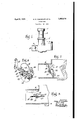
- Figure 1 is a side elevation partly in section showing the choke valve installed ina carburetor
- Figure 2 is a sectional view to asomewhat larger scale showing the manually controlled valve in the closed position and the hinged portion in two of its operative positions;
- FIG. 3 is similar to Figure2 except that the manually operated valve is shown in. its open position;
- Figure 4 is a perspective view of the choke valve showing the various parts arranged in approximately the same position as they assume in their assembled relation.
- 1 is a carburetor of the usual construction connected to an engine manifold 2 and having "a'manually operated throttle valve 4 which is located between the mixture chamber 6 of the carburetor and the manifold 2.
- the air intake 59 .of the carburetor 1 is through the'air horn 8 stantially in proportion to the needs of the 22 which extend-within the cut-out portions erablyis so arranged as to prevent movementwithin which is located a choke valve generally designated as 10 in Figure 1.
- the choke valve is ordinarily used only during the starting-operation of the engine and for a short time thereafter until the engine has become sufiiciently heated to operate on the normal mixture delivered by the carburetor. .
- the choke valve is completely closed by the operator and remains closed until the engine starts to fire, at-which time the choke valve is slightly opened and adjusted to a position which, in the opinion of the operator, gives the most satisfactory performance.
- the present invention overcomes this tendency to over-enrichment by providing a choke valve formed in two parts, one of which is hinged and which maybe opened by the sudden inrush of air that is produced by the starting of the engine.
- the present choke valve is,-to a certain extent, automatic and will be opened or closed subengine.
- the choke is operated by a lever 12 which is secured to a shaft 14 having hearin s in opposite sides of the air horn 8. In the us trated embodiment, the shaft.
- LA spring member 26 is secured to oneof-thevalv'e portions by any desired meanssuch as rivet 28 and has its opposite end connected a block 30 preferably faced with leather or similar 1 material which is in slidable contact with valve 20.
- lever 12 is move by any suitable means, not shown, to cause the choke valve to close the air horn 8 and assume the position shown in full lines in Figure 2.
- valve portion 20 contacts with the wall of the air horn 8 prior to the closing of valve 16 so that in the closed position valve 20 is slightly inclined to the plane of the manually operated valve.
- the engine starts'to o erate, it will immediately cause air to drawn in through the air born 8 and the hinged portion 20 will assume the position shown in dotted lines in Figure 2.
- the extent of opening will be dependent upon the quantity of air drawn in by the engine and, therefore the opening will automatically assume a size substantially proportional to the needs of the engine.
- valve will be manually moved to the po- .lowing claims.
- a choke valve having a shaft, a pair of flat valve portions, one of said portions being secured to the shaftand the other ournalled thereon, resilient means urging the journalled portion toward the plane of the secured portion, a stop preventing the journalled portion from moving beyond the plane of the other portion, and means for rotating the shaft.
- a valve for a carburetor air passage comprising a shaft, a semicircular valve portion fixed to the shaft, a semicircular valve portion journaled on the shaft, and yielding means tending to maintain the valve portions in a common plane.
- a valve for a carburetor air passage comprising a shaft, a valve portion fixed to the shaft, a second valve portion journaled on the shaft, and resilient means fixed to the first mentioned portion and frictionally engaging the journaled portion to urge the valve portions into a common plane.
- Ayalve for an air passage comprising a shaft, a valve portion fixed to the shaft, a second valve portion rotatably related to the shaft, a frictional member engaging the second portion, and yielding means connecting the frictional member to the first mentioned portion.
- a valve for a fluid conduit comprising a shaft adapted to be journaled in the walls of the conduit for manual operation, a valve portion fixed to the shaft, a second valve portion rotatably related-to the shaft, a member having a frictional surface slidably engaging the second portion, and a spring connecting the frictional member to the first mentioned portion to urge the two'portions means tending to maintain the valve portions in a common plane against the influence of fluid pressure, the second portion being so shaped with relation to the conduitthat whcn the first stipulated portion is moved to closed position the second portion is moved out of alinement with the first mentioned portion by its engagement with the walls of the conduit.
- a valve for a fluid conduit comprising a manually operable shaft, a valve portion fixed to the shaft and shaped to assume a closed position approximately normal-to the axis of the shaft, and a second valve )ortion hingedly and yieldingly related to t e first mentioned portion and shaped to assume a closed position out of alinement with the closed position of the first mentioned portion.
- a valve for an air conduit comprising a shaft, a valve portion fixed to the shaft, a second valve portion movably related to the shaft and adapted to be brought into engagement with the interior of the conduit by rotation of the valve as a whole, the first mentioned valve portion being capable of further rotation after such engagement, and yielding means tending to maintain the portions in alinement and put under tension by
Landscapes
- Engineering & Computer Science (AREA)
- Chemical & Material Sciences (AREA)
- Combustion & Propulsion (AREA)
- Mechanical Engineering (AREA)
- General Engineering & Computer Science (AREA)
- Means For Warming Up And Starting Carburetors (AREA)
Description
Ap 5, 1932- M. E. CHANDLER ET AL 1,852,918
CARBURETOR Filed Nov. 24, 1930 Par; Co/e Y Patented Apr. 5, 1932 UNITED STATES PATENT-OFFICE MILTON n CHANDLER, or sou'riI BEND, INDIANA, AND 'noNfcorn, or EvaNsroN, ILLINOIS; SAID CHANDLER ASSIGNOB 'ro BENpIx-s'rnounnne cmsunnron com,- PANY, or some: BEND; INDIANA, A CORPORATION or rumors cannmmron Application filed November 24, 1930. Serial No. 497,684;
This invention relates to choke valves for carburetors and has for one of its objects the elimination of over-enrichment of the mixture after the engine to which the carburetor is attached has started tooperateand is illustrated as embodied in a carburetorof the conventional type.
One feature of the invention resides in the novelsegmental valve construction in which one valve portion is resiliently hinged on the operating shaft in a manner to be opened by the pressure of the air drawn through the carburetor by the engine.
An important characteristic of the invention relates to the arrangement of a spring for closing the valve which coacts between the segmental portions and permits manual operation of the valve without changing the spring tension. A stop is also provided on go one ofthe valve portions which abuts the other valve portionand locates the hinged valve parallel to the air stream in the open position of the manually operated valve.
Other objects and novel features of con-' struction and operation will appear from the following description in connection with which we have illustrated one embodiment.
Figure 1 is a side elevation partly in section showing the choke valve installed ina carburetor; v
Figure 2 is a sectional view to asomewhat larger scale showing the manually controlled valve in the closed position and the hinged portion in two of its operative positions;
Figure 3 is similar to Figure2 except that the manually operated valve is shown in. its open position; and
Figure 4 is a perspective view of the choke valve showing the various parts arranged in approximately the same position as they assume in their assembled relation.
Referring to the drawings, 1 is a carburetor of the usual construction connected to an engine manifold 2 and having "a'manually operated throttle valve 4 which is located between the mixture chamber 6 of the carburetor and the manifold 2. The air intake 59 .of the carburetor 1 is through the'air horn 8 stantially in proportion to the needs of the 22 which extend-within the cut-out portions erablyis so arranged as to prevent movementwithin which is located a choke valve generally designated as 10 in Figure 1.
The choke valve is ordinarily used only during the starting-operation of the engine and for a short time thereafter until the engine has become sufiiciently heated to operate on the normal mixture delivered by the carburetor. .In the ordinary procedure for starting of a cold engine, the choke valve is completely closed by the operator and remains closed until the engine starts to fire, at-which time the choke valve is slightly opened and adjusted to a position which, in the opinion of the operator, gives the most satisfactory performance. It frequently happens that the operator is unable to determine the best position of the valve, or is unable to open it fast enough to adjust it to the speed'of the engine which results in the delivery of an excessive amount of fuel and causes the engine to The present invention overcomes this tendency to over-enrichment by providing a choke valve formed in two parts, one of which is hinged and which maybe opened by the sudden inrush of air that is produced by the starting of the engine. In other words, the present choke valve is,-to a certain extent, automatic and will be opened or closed subengine. Y The choke is operated by a lever 12 which is secured to a shaft 14 having hearin s in opposite sides of the air horn 8. In the us trated embodiment, the shaft. 14 is split lengthwise and the manually operated portion 16 is clamped between the-.halvesby screws 18. The hinged portion 20' is journalled upon the shaft by hearing portions 24 of valve 16 and prevent the hinged valve from moving axially of the shaft. Afstop 23 is provided which limits the movement of valve 20 toward its closed position and prefbeyond the plane of the valve 16. LA spring member 26 is secured to oneof-thevalv'e portions by any desired meanssuch as rivet 28 and has its opposite end connected a block 30 preferably faced with leather or similar 1 material which is in slidable contact with valve 20. In the normal 0 eration of the choke valve, lever 12 is move by any suitable means, not shown, to cause the choke valve to close the air horn 8 and assume the position shown in full lines in Figure 2.
It will be noted that in Figure 2 valve portion 20 contacts with the wall of the air horn 8 prior to the closing of valve 16 so that in the closed position valve 20 is slightly inclined to the plane of the manually operated valve. As soon as the engine starts'to o erate, it will immediately cause air to drawn in through the air born 8 and the hinged portion 20 will assume the position shown in dotted lines in Figure 2. The extent of opening will be dependent upon the quantity of air drawn in by the engine and, therefore the opening will automatically assume a size substantially proportional to the needs of the engine.
After the engine has become sufiiciently heated to operate under a normal mixture,
' the valve will be manually moved to the po- .lowing claims.
sition shown in Figure 3, wherein the spring 26 has forced the valve 20 to a position in which the stop 22 is in contact with the portion 16 and both of the segmental valves lie in a plane parallel to the normal flow of air through the air horn.
It will be apparent from the above description of the illustrative embodiment that we have illustrated and described a choke valve which is semi-automatic in its operation and which, to a certain extent, will counteract the tendency of'the operator to retain the choke valve in an incorrect position.
While we have illustrated and described in considerable detail one illustrative em bodiment of the invention, it is to be understood that we do not regard the invention as limited to the form shown and described or otherwise except by the terms of the fol- Having thus described the various features of the invention, what we claim as new and desire to secure by Letters Patent is:
1. A choke valve having a shaft, a pair of flat valve portions, one of said portions being secured to the shaftand the other ournalled thereon, resilient means urging the journalled portion toward the plane of the secured portion, a stop preventing the journalled portion from moving beyond the plane of the other portion, and means for rotating the shaft.
2. A valve for a carburetor air passage, comprising a shaft, a semicircular valve portion fixed to the shaft, a semicircular valve portion journaled on the shaft, and yielding means tending to maintain the valve portions in a common plane.
3. A valve for a carburetor air passage comprising a shaft, a valve portion fixed to the shaft, a second valve portion journaled on the shaft, and resilient means fixed to the first mentioned portion and frictionally engaging the journaled portion to urge the valve portions into a common plane.
4. Ayalve for an air passage, comprising a shaft, a valve portion fixed to the shaft, a second valve portion rotatably related to the shaft, a frictional member engaging the second portion, and yielding means connecting the frictional member to the first mentioned portion.
5. A valve for a fluid conduit, comprising a shaft adapted to be journaled in the walls of the conduit for manual operation, a valve portion fixed to the shaft, a second valve portion rotatably related-to the shaft, a member having a frictional surface slidably engaging the second portion, and a spring connecting the frictional member to the first mentioned portion to urge the two'portions means tending to maintain the valve portions in a common plane against the influence of fluid pressure, the second portion being so shaped with relation to the conduitthat whcn the first mentined portion is moved to closed position the second portion is moved out of alinement with the first mentioned portion by its engagement with the walls of the conduit. Y
7. A valve for a fluid conduit, comprising a manually operable shaft, a valve portion fixed to the shaft and shaped to assume a closed position approximately normal-to the axis of the shaft, and a second valve )ortion hingedly and yieldingly related to t e first mentioned portion and shaped to assume a closed position out of alinement with the closed position of the first mentioned portion. i I
8. A valve for an air conduit comprising a shaft,a valve portion fixed to the shaft, a second valve portion movably related to the shaft and adapted to be brought into engagement with the interior of the conduit by rotation of the valve as a whole, the first mentioned valve portion being capable of further rotation after such engagement, and yielding means tending to maintain the portions in alinement and put under tension by
Priority Applications (1)
| Application Number | Priority Date | Filing Date | Title |
|---|---|---|---|
| US497664A US1852918A (en) | 1930-11-24 | 1930-11-24 | Carburetor |
Applications Claiming Priority (1)
| Application Number | Priority Date | Filing Date | Title |
|---|---|---|---|
| US497664A US1852918A (en) | 1930-11-24 | 1930-11-24 | Carburetor |
Publications (1)
| Publication Number | Publication Date |
|---|---|
| US1852918A true US1852918A (en) | 1932-04-05 |
Family
ID=23977794
Family Applications (1)
| Application Number | Title | Priority Date | Filing Date |
|---|---|---|---|
| US497664A Expired - Lifetime US1852918A (en) | 1930-11-24 | 1930-11-24 | Carburetor |
Country Status (1)
| Country | Link |
|---|---|
| US (1) | US1852918A (en) |
Cited By (13)
| Publication number | Priority date | Publication date | Assignee | Title |
|---|---|---|---|---|
| US2525931A (en) * | 1946-04-19 | 1950-10-17 | Addressograph Multigraph | Plate mounting means for rotary printing machines |
| US2531896A (en) * | 1946-10-12 | 1950-11-28 | Louis E Telbizoff | Variable area nozzle |
| US2615470A (en) * | 1947-04-23 | 1952-10-28 | Everett H Bickley | Magnetic air valve |
| US2808042A (en) * | 1951-03-21 | 1957-10-01 | Robert H Thorner | Speed controlled engine or the like |
| US3053242A (en) * | 1959-09-03 | 1962-09-11 | Michael A Arpaia | Carbureting system |
| US3116016A (en) * | 1961-12-07 | 1963-12-31 | Honeywell Regulator Co | Air conditioning apparatus having volume and temperature control |
| US3159334A (en) * | 1963-03-13 | 1964-12-01 | Ametek Inc | Fan |
| US3971414A (en) * | 1974-04-02 | 1976-07-27 | Kieley & Mueller, Inc. | Servo butterfly valve and vane |
| US5174547A (en) * | 1990-10-02 | 1992-12-29 | Alcatel Cit | Butterfly valve for limiting sudden variations in gas flow along a duct |
| US5738276A (en) * | 1995-03-31 | 1998-04-14 | Behr-Thomson Dehnstoffregler Gmbh & Co. | Valve |
| US20130149955A1 (en) * | 2011-12-13 | 2013-06-13 | Ronald E. Jackson | Barometric relief air zone damper |
| USD743521S1 (en) | 2014-06-12 | 2015-11-17 | Controlled Holdings, Llc | Zone damper |
| US11359732B1 (en) * | 2021-04-07 | 2022-06-14 | Applied Materials, Inc. | Method and mechanism for symmetrically controlling pressure in process chamber |
-
1930
- 1930-11-24 US US497664A patent/US1852918A/en not_active Expired - Lifetime
Cited By (15)
| Publication number | Priority date | Publication date | Assignee | Title |
|---|---|---|---|---|
| US2525931A (en) * | 1946-04-19 | 1950-10-17 | Addressograph Multigraph | Plate mounting means for rotary printing machines |
| US2531896A (en) * | 1946-10-12 | 1950-11-28 | Louis E Telbizoff | Variable area nozzle |
| US2615470A (en) * | 1947-04-23 | 1952-10-28 | Everett H Bickley | Magnetic air valve |
| US2808042A (en) * | 1951-03-21 | 1957-10-01 | Robert H Thorner | Speed controlled engine or the like |
| US3053242A (en) * | 1959-09-03 | 1962-09-11 | Michael A Arpaia | Carbureting system |
| US3116016A (en) * | 1961-12-07 | 1963-12-31 | Honeywell Regulator Co | Air conditioning apparatus having volume and temperature control |
| US3159334A (en) * | 1963-03-13 | 1964-12-01 | Ametek Inc | Fan |
| US3971414A (en) * | 1974-04-02 | 1976-07-27 | Kieley & Mueller, Inc. | Servo butterfly valve and vane |
| US5174547A (en) * | 1990-10-02 | 1992-12-29 | Alcatel Cit | Butterfly valve for limiting sudden variations in gas flow along a duct |
| US5738276A (en) * | 1995-03-31 | 1998-04-14 | Behr-Thomson Dehnstoffregler Gmbh & Co. | Valve |
| US20130149955A1 (en) * | 2011-12-13 | 2013-06-13 | Ronald E. Jackson | Barometric relief air zone damper |
| US8956207B2 (en) * | 2011-12-13 | 2015-02-17 | Controlled Holdings, Llc | Barometric relief air zone damper |
| US9033778B2 (en) | 2011-12-13 | 2015-05-19 | Controlled Holdings, Llc | Barometric relief air zone damper |
| USD743521S1 (en) | 2014-06-12 | 2015-11-17 | Controlled Holdings, Llc | Zone damper |
| US11359732B1 (en) * | 2021-04-07 | 2022-06-14 | Applied Materials, Inc. | Method and mechanism for symmetrically controlling pressure in process chamber |
Similar Documents
| Publication | Publication Date | Title |
|---|---|---|
| US1852918A (en) | Carburetor | |
| US2998233A (en) | Automatic choke | |
| US2979047A (en) | Automatic choke for small carburetors | |
| US2065167A (en) | Choke valve | |
| US2215682A (en) | Carburetor | |
| US2140734A (en) | Carburetor choke valve | |
| US3151189A (en) | Carburetor | |
| US4113808A (en) | Carburetor having an automatic choke | |
| US2098202A (en) | Carburetor | |
| US2402361A (en) | Carburetor | |
| US3321194A (en) | Carburetor | |
| US2665891A (en) | Antistall device | |
| US2140776A (en) | Carburetor | |
| US2215614A (en) | Carburetor | |
| US2166899A (en) | Carburetor structure | |
| USRE22968E (en) | stanton | |
| US4171686A (en) | Carburation devices with idle adjustment | |
| US2093961A (en) | Automatic carburetor | |
| USRE22030E (en) | Carburetor valve | |
| US2538570A (en) | Automatic choke | |
| US2030331A (en) | Carburetor | |
| US1828415A (en) | Carburetor | |
| US2074728A (en) | Carburetor | |
| US2346016A (en) | Carburetor | |
| US2173191A (en) | Combustible mixture regulating mechanism |