US1852917A - Builder's bridging structure - Google Patents
Builder's bridging structure Download PDFInfo
- Publication number
- US1852917A US1852917A US437325A US43732530A US1852917A US 1852917 A US1852917 A US 1852917A US 437325 A US437325 A US 437325A US 43732530 A US43732530 A US 43732530A US 1852917 A US1852917 A US 1852917A
- Authority
- US
- United States
- Prior art keywords
- joists
- loops
- builder
- bridging
- strip
- Prior art date
- Legal status (The legal status is an assumption and is not a legal conclusion. Google has not performed a legal analysis and makes no representation as to the accuracy of the status listed.)
- Expired - Lifetime
Links
- 229910000831 Steel Inorganic materials 0.000 description 1
- 238000009435 building construction Methods 0.000 description 1
- 239000010959 steel Substances 0.000 description 1
- 210000001364 upper extremity Anatomy 0.000 description 1
Images
Classifications
-
- E—FIXED CONSTRUCTIONS
- E04—BUILDING
- E04C—STRUCTURAL ELEMENTS; BUILDING MATERIALS
- E04C3/00—Structural elongated elements designed for load-supporting
- E04C3/02—Joists; Girders, trusses, or trusslike structures, e.g. prefabricated; Lintels; Transoms; Braces
-
- E—FIXED CONSTRUCTIONS
- E04—BUILDING
- E04C—STRUCTURAL ELEMENTS; BUILDING MATERIALS
- E04C3/00—Structural elongated elements designed for load-supporting
- E04C3/02—Joists; Girders, trusses, or trusslike structures, e.g. prefabricated; Lintels; Transoms; Braces
- E04C2003/026—Braces
Definitions
- Patented Apia .5; 1932 UNI? vneeino. BURGETT, or LonAIN; onto I BUILDERS nrneine srnnorunn Application filed March 20, 1930.- Serial No. 437,325.
- This invention isa bridging or tying device to be used in building construction between floor joists or the like.
- One object of the invention is to provide a structure of this kind especially adapted for use with steel bar joists now in common use.
- 'Another object is to provide -a form of bridge strip for connecting joists in buidings, includingspaced and squared loops adapted to seat snugly over the tops of the joists and to automatic-ally center the extend straight down the sides thereof substantiallytowards the bottoms thereof, the said loops being connected by straight across 7 reaches for maintaining in an edgewise vertical position oists having otherwise a tendency to warp or twist sidewise-
- a further object of the invention is to provide in a relatively simple and strong form, astructure of the kind which will serve to joists as the bridging is laid down.
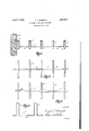
- Figure 1 is a side elevationof a strip of.
- Figure2 is a plan view showing a number of sections of floor joists as connected by a strip of bridging made in accordance with this invention
- Figure 3 is a plan view showing a number of sections of floor joists as connected by two strips of the bridging, and illustrating themethod of oining the ends of two such strips, the ends being positioned side by side and thus held or otherwise'securedtogether;
- Figure at is an enlarged detail'view of a section of the bridgingstrip.
- the invention consists in aform of bridg-f lng or bridge strip 1 .ma deof strip; 11'011. or
- the endslof the bridge stripsl may be anchored in the side walls, one of which is shown at 5, in any suitable manner, as by a right angled bend 6 seated in the masonry.
- the bridge strips 1 may be cut to order to meet the width of the building, or for wide structures, two
- strips. 1 have the loops 2 regularly spacedapart to the desired distance, the said loops as they arelaid down serve to auto matically center the joists 3.
Landscapes
- Engineering & Computer Science (AREA)
- Architecture (AREA)
- Civil Engineering (AREA)
- Structural Engineering (AREA)
- Building Environments (AREA)
Description
A ril 5%, 1932 v. c. BURGETT BUILDERS BRIDGING STRUCTURE Filed March 20',
b u m w H M W m & d
Patented Apia: .5; 1932 UNI? vneeino. BURGETT, or LonAIN; onto I BUILDERS nrneine srnnorunn Application filed March 20, 1930.- Serial No. 437,325.
This inventionisa bridging or tying device to be used in building construction between floor joists or the like. One object of the invention is to provide a structure of this kind especially adapted for use with steel bar joists now in common use.
'Another object is to provide -a form of bridge strip for connecting joists in buidings, includingspaced and squared loops adapted to seat snugly over the tops of the joists and to automatic-ally center the extend straight down the sides thereof substantiallytowards the bottoms thereof, the said loops being connected by straight across 7 reaches for maintaining in an edgewise vertical position oists having otherwise a tendency to warp or twist sidewise- A further object of the invention is to provide in a relatively simple and strong form, astructure of the kind which will serve to joists as the bridging is laid down.
V In the drawings Figure 1 is a side elevationof a strip of.
bridging constructed and laid in accordance with this invention, a side wall and a number of joists being shown in section;
Figure2 is a plan view showing a number of sections of floor joists as connected bya strip of bridging made in accordance with this invention;
Figure 3 is a plan view showing a number of sections of floor joists as connected by two strips of the bridging, and illustrating themethod of oining the ends of two such strips, the ends being positioned side by side and thus held or otherwise'securedtogether;
Figure at is an enlarged detail'view of a section of the bridgingstrip.
The invention consists in aform of bridg-f lng or bridge strip 1 .ma deof strip; 11'011. or
other suitablematerial of about one and onehalf inches'width and one-eighth inch thickness, or as may be desired. These strips are L bentas shownin the drawings to form'spaced n) grally connected by the horizontally extended and squared loops 2 adapted to seatsnugly over the floor joists 3 which are regularly spaced apart; The loops 2 extend below the longitudinal axis of the joists'and are intereaches 4. Thus the reaches 4 extendstraight across from joist to joist below their axes and are most advantageously positioned to pre- Vent warping or twisting of thejoists. The endslof the bridge stripsl may be anchored in the side walls, one of which is shown at 5, in any suitable manner, as by a right angled bend 6 seated in the masonry. The bridge strips 1 may be cut to order to meet the width of the building, or for wide structures, two
or more strips maybe joined or spliced together attheir ends as shown at 7. Inasmuch as the strips. 1 have the loops 2 regularly spacedapart to the desired distance, the said loops as they arelaid down serve to auto matically center the joists 3.
necting the joists'andhaving spaced loops adapted to seat snugly'over the tops of the oists and extend straight down the sides and i below the longitudinal axes of the joists to resist twisting stresses on the oists,the ends of the strip belng extendedoutward from the upper extremities of the loops nearest 8 the ends of the strip and being bent upward and anchored in thesaid walls of the build- In testimony whereof Ijaflix my signature.
VIRGIL C. BURGETT.
Priority Applications (1)
| Application Number | Priority Date | Filing Date | Title |
|---|---|---|---|
| US437325A US1852917A (en) | 1930-03-20 | 1930-03-20 | Builder's bridging structure |
Applications Claiming Priority (1)
| Application Number | Priority Date | Filing Date | Title |
|---|---|---|---|
| US437325A US1852917A (en) | 1930-03-20 | 1930-03-20 | Builder's bridging structure |
Publications (1)
| Publication Number | Publication Date |
|---|---|
| US1852917A true US1852917A (en) | 1932-04-05 |
Family
ID=23735969
Family Applications (1)
| Application Number | Title | Priority Date | Filing Date |
|---|---|---|---|
| US437325A Expired - Lifetime US1852917A (en) | 1930-03-20 | 1930-03-20 | Builder's bridging structure |
Country Status (1)
| Country | Link |
|---|---|
| US (1) | US1852917A (en) |
Cited By (4)
| Publication number | Priority date | Publication date | Assignee | Title |
|---|---|---|---|---|
| US3010162A (en) * | 1957-05-20 | 1961-11-28 | Lewis D Klein | Strip brace |
| US4856247A (en) * | 1987-04-06 | 1989-08-15 | Georgino John M | Article and method for installing insulation |
| US5678371A (en) * | 1996-01-24 | 1997-10-21 | Wills; Mark E. | Vapor barrier panel for use in a building structure |
| US11866934B1 (en) * | 2021-05-04 | 2024-01-09 | Joshua Julian Jordan | Method for insulating pier and beam historic foundations |
-
1930
- 1930-03-20 US US437325A patent/US1852917A/en not_active Expired - Lifetime
Cited By (4)
| Publication number | Priority date | Publication date | Assignee | Title |
|---|---|---|---|---|
| US3010162A (en) * | 1957-05-20 | 1961-11-28 | Lewis D Klein | Strip brace |
| US4856247A (en) * | 1987-04-06 | 1989-08-15 | Georgino John M | Article and method for installing insulation |
| US5678371A (en) * | 1996-01-24 | 1997-10-21 | Wills; Mark E. | Vapor barrier panel for use in a building structure |
| US11866934B1 (en) * | 2021-05-04 | 2024-01-09 | Joshua Julian Jordan | Method for insulating pier and beam historic foundations |
Similar Documents
| Publication | Publication Date | Title |
|---|---|---|
| US2088781A (en) | Studding structure | |
| US2017553A (en) | Form for plastic structural work | |
| US2558946A (en) | Reinforced cast structure | |
| US2200159A (en) | Construction element | |
| US2108065A (en) | Building construction and structural element therefor | |
| US1852917A (en) | Builder's bridging structure | |
| US2578465A (en) | Metal joist | |
| US2241617A (en) | Triangular joist | |
| US4333293A (en) | Joist having differing metal web reinforcement | |
| US1864043A (en) | Form for making fireproof floor constructions | |
| US2084853A (en) | Floor and ceiling support | |
| US1817619A (en) | Roof | |
| US2061103A (en) | Truss | |
| US1597384A (en) | Steel joist | |
| US1871976A (en) | Sheet metal form and sheet metal lath | |
| US1852042A (en) | Fabricated metal structural member | |
| US1973882A (en) | Roof truss | |
| US1241793A (en) | Hollow metal tile for reinforced-concrete floors. | |
| US3561184A (en) | Corrugated deck joist | |
| US2065796A (en) | Ceiling structure | |
| US2285165A (en) | Building floor | |
| US2309823A (en) | Fabricated steel beam | |
| US2318214A (en) | Form for casting concrete floor beams | |
| US1935758A (en) | Truss | |
| US2257762A (en) | Panel and joist |