US1852916A - Coupler for toy cars - Google Patents
Coupler for toy cars Download PDFInfo
- Publication number
- US1852916A US1852916A US563616A US56361631A US1852916A US 1852916 A US1852916 A US 1852916A US 563616 A US563616 A US 563616A US 56361631 A US56361631 A US 56361631A US 1852916 A US1852916 A US 1852916A
- Authority
- US
- United States
- Prior art keywords
- coupler
- car
- couplers
- cars
- coupling
- Prior art date
- Legal status (The legal status is an assumption and is not a legal conclusion. Google has not performed a legal analysis and makes no representation as to the accuracy of the status listed.)
- Expired - Lifetime
Links
- 230000008878 coupling Effects 0.000 description 14
- 238000010168 coupling process Methods 0.000 description 14
- 238000005859 coupling reaction Methods 0.000 description 14
- 210000005069 ears Anatomy 0.000 description 11
- 230000003137 locomotive effect Effects 0.000 description 11
- 238000010276 construction Methods 0.000 description 8
- 230000005484 gravity Effects 0.000 description 6
- 230000013011 mating Effects 0.000 description 2
- XNPKNHHFCKSMRV-UHFFFAOYSA-N 4-(cyclohexylamino)butane-1-sulfonic acid Chemical compound OS(=O)(=O)CCCCNC1CCCCC1 XNPKNHHFCKSMRV-UHFFFAOYSA-N 0.000 description 1
- 230000015572 biosynthetic process Effects 0.000 description 1
- 230000000694 effects Effects 0.000 description 1
- 230000008520 organization Effects 0.000 description 1
Images
Classifications
-
- A—HUMAN NECESSITIES
- A63—SPORTS; GAMES; AMUSEMENTS
- A63H—TOYS, e.g. TOPS, DOLLS, HOOPS OR BUILDING BLOCKS
- A63H19/00—Model railways
- A63H19/16—Parts for model railway vehicles
- A63H19/18—Car coupling or uncoupling mechanisms
Definitions
- This invention relates to toy railroads, and
- the invention contemplates a coupling device for toy trains that will permit of the coupling of one car to another car; a car to a locomotive; or a locomotive to a locomotive.
- the invention has in view a coupler of the manual type, using asfew' as cssible, and these parts being of strong and substantial construction, thereby to successfully withstand the severe handling to which: toys of this type are sometimes subjected.
- Another object of the invention is to pro-- vide a universal coupler, or one that does not require a male'and female coupler at each end of a car or locomotive; That: is to say, the invention has in view a coupler whichis identical in every respect and on being at .tached to a car orrlocomotive will readily couple with another car'or locomotive, with: out the necessity of turning the car orlocomotive end for end in order to successfully en age the couplers;
- a further obj ect ofthe invention is to provide a coupler which .will couple perfectly with a number of other types of couplers already onthe market thus obviating any necessity for changing the couplers on an old type car or locomotive to conform with the present device. 1 a
- a still further object of the invention isto in uncoupled relation.
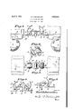
- Figure 1 is a side elevation of the ends of twocars coupled together with thecoupler constituting the present invention.
- Figure 2 is a top plan viewof the construction shown in Figure 1.
- FIG. 3 is a detail view of mating couplers
- Figure 4 is a perspective view of the pivoted gravity latch constituting apart of the presentcoupler.
- F'gure 5 is a view illustrating the manner of coupling one of the couplers'of the present invention with an odd type of coupling now in general use.
- the present coupler includes a pivoted gravity latch designated generally as A; a shank unit designated as B and a pin unit C for connecting the latch and the shank.
- A pivoted gravity latch
- B shank unit
- C pin unit
- the gravity latch unit A includes a body section 1 provided at one end with an upturned forwardly curved handle portion 2- while the other end is provided with a depending hook or keeper shank 3 formed at its lower end with the outwardly projecting ears 4.
- the body 2 is provided adjacent the hook 3 with a transverse keeper slot 5 for receiving the hook 3 of a mating coupler.
- the body 1 is provided with the down-turned ears 6 provided with openings 7 for receiving the coupling pins C, as will presently appear.
- the coupler shank B is provided at its inner end with an opening 8 for receiving a suitable fastening 9 for freely pivoting the shank to the bottom of the car so that it may swing in a horizontal direction.
- the outer or forward end of the shank is turned upwardly as indicated at 10 so that the upper edge of the upturned portion may constitute a rest or supporting ledge for the pivoted latch member when the latter is in its normal position.
- the sides of the body of the shank adjacent the upturned abutment wall 10 are formed with the upstanding cars 11 so spaced as to receive therebetwcen the downturned ears 6 of the latch member A.
- the ears 11 are provided with a suitable opening so that when the latch member and shank are in assembled relation the coupling pin C may be inserted to hold them together and form the axis and support for the pivoted latch gravity member A.
- the handle 2 is formed upwardly in such a manner that it is easily and always readily accessible under all operating conditions and when it is desired to couple two cars or a locomotive and a car together, the two cou plers are caused to approach each other, the latch unit A of one coupler being swung upwardly by means of the handle on the pivot pin C. At the moment of engagement the coupler handle 2 is released by gravity causing the hook or keeper shank 3 of the raised or elevated coupler to fall into the transverse keeper slot 5 of the opposite coupler. For uncoupling, the handle 2 is manipulated so as to withdraw the hook or keeper shank 3 from the slot 5, thus simply and expeditiously effecting uncoupling.
- the ears 4 on the hook 3 form a natural obstacle to the accidental release or disengagement of the couplers. Furthermore these ears positively insure a coupling engagement when a train is backing up since this operation usually forces a coupler upward and might thus effect uncoupling. On the other hand, the ears 4 do not interfere with the manual operation of coupling or uncoupling inasmuch as they are rounded at the corners and easily disengaged from a keeper slot of another coupler.
- the spacing of the cars 11 is such that the latch A will have sufficient clearance to properly engage an opposite coupler and allow clearance between itself and the opposite coupler so that the ordinary operation of a train in either a forward or backward direction will not cause the couplers to drag and possibly derail the car or locomotive.
- coupler is more effective and easier to operate than couplers employing springs and the like, and furthermore since no springs are required the usual. objections incident to such parts are avoided.
- a coupler for toy cars comprising a shank member adapted to be pivoted at one end to the car body and formed at the other end with an upturned abutment wall and upturned side walls adjacent thereto, said side Walls providing pivot ears, and a gravity latch pivoted in said ears and comprising a body adapted normally to rest upon said abutment wall, said body being turned downwardly at its front end to provide a coupling hook and turned upwardly at its other end to provide a handle, and said bod being further provided adjacent the coup ing hook with a slot and adjacent the handle with downturned pivot ears.
Landscapes
- Toys (AREA)
Description
Aprll 1932- E. D. BOISSELIER COUPLER FOR TOY CARS Filed Sept. 18, 1951 w e a w M w W E B Patented Apr. I 5, 1932 UNITED; suites PATENT) emu-1+ .I)..BOISSE LI ER,.OF CHICAGO, ILLINOIS, ASSIGNOR TO AMERICAN FLYER MFGJCO 7 OF? CHICAGO; ILLINOIS, A'CORPORATION OF ILLINOIS CO'UPLER FOR 'I'OY CABS Application-filed September 18,1931. Serial No. 563,616.
This invention relates to toy railroads, and
has particular reference to a novel improvement in car couplers for connecting the cars in train formation.
To that end the invention contemplates a coupling device for toy trains that will permit of the coupling of one car to another car; a car to a locomotive; or a locomotive to a locomotive. In .that connection, the invention has in view a coupler of the manual type, using asfew' as cssible, and these parts being of strong and substantial construction, thereby to successfully withstand the severe handling to which: toys of this type are sometimes subjected.
Another object of the invention is to pro-- vide a universal coupler, or one that does not require a male'and female coupler at each end of a car or locomotive; That: is to say, the invention has in view a coupler whichis identical in every respect and on being at .tached to a car orrlocomotive will readily couple with another car'or locomotive, with: out the necessity of turning the car orlocomotive end for end in order to successfully en age the couplers;
other object of the invention is to pro-' vide a simple, strongly constructed coupler which has a low assembly cost'and which a child or person totally unfamiliar with toy train operation or construction can successfully, easily and readily complete thecoupling and uncoupling operationwithout instruction and without removing the car or locomotive from the track. Many couplers on toy trains are of such complicatedmechanical construction that considerable skill is required to successfully couple and uncouple a caror locomotive without removing same from track and carefully studyingthe construction and operation of the particular type of coupler. s
A further obj ect ofthe invention is to provide a coupler which .will couple perfectly with a number of other types of couplers already onthe market thus obviating any necessity for changing the couplers on an old type car or locomotive to conform with the present device. 1 a
A still further object of the invention isto in uncoupled relation. I a
provide a coupler which will not buckle when pushing cars around a curve; that is to say,
it. is proposed to provide a coupler which will transmit the pushing force of the locomotive from one car to another through the rigid coupling itself rather than cause the coupling to break at the point of connection and move to one sideso that thepushing-force is imparted by car to car contact if there is enough play in they couplings to permit the force to result in a side thrust thathas a tendency to derail the cars. When cars are being pulled the couplers of course'readily stay in proper alinement, but when cars are being pushed thereis always a tendency in couplers heretofore constructed for theparts to break alinement' and movetoone side or the other at the point of connection of one. car with another. The present construction however, obviates that objection and provides a coupling which .will not buckle on curves when cars are being pushed or being With the aboveand other objects in-view which will more readily appear as the nature of the invention is better understood, the
same consists in the novel construction, com-, bination and arrangements of parts hereinafter morefully described, illustrated and claimed. I
A preferred and practical embodiment of the invention is shown in the accompanying drawings, in which Figure 1 is a side elevation of the ends of twocars coupled together with thecoupler constituting the present invention.
Figure 2 is a top plan viewof the construction shown inFigure 1.
a Figure 3 is a detail view of mating couplers Figure 4 is a perspective view of the pivoted gravity latch constituting apart of the presentcoupler. i 7
F'gure 5 isa view illustrating the manner of coupling one of the couplers'of the present invention with an odd type of coupling now in general use.
Similar reference characters designate corresponding parts throughout the several fig ures of :the drawings.
t de
In its general organization the present coupler includes a pivoted gravity latch designated generally as A; a shank unit designated as B and a pin unit C for connecting the latch and the shank. In practice the a complete coupler, thereby permitting the ready coupling of one car to another.
Referrin first to the gravity latch unit A it will be 0 served that the same includes a body section 1 provided at one end with an upturned forwardly curved handle portion 2- while the other end is provided with a depending hook or keeper shank 3 formed at its lower end with the outwardly projecting ears 4. The body 2 is provided adjacent the hook 3 with a transverse keeper slot 5 for receiving the hook 3 of a mating coupler. Also adjacent the upturned handle 2, the body 1 is provided with the down-turned ears 6 provided with openings 7 for receiving the coupling pins C, as will presently appear.
The coupler shank B is provided at its inner end with an opening 8 for receiving a suitable fastening 9 for freely pivoting the shank to the bottom of the car so that it may swing in a horizontal direction. The outer or forward end of the shank is turned upwardly as indicated at 10 so that the upper edge of the upturned portion may constitute a rest or supporting ledge for the pivoted latch member when the latter is in its normal position. The sides of the body of the shank adjacent the upturned abutment wall 10 are formed with the upstanding cars 11 so spaced as to receive therebetwcen the downturned ears 6 of the latch member A. The ears 11 are provided with a suitable opening so that when the latch member and shank are in assembled relation the coupling pin C may be inserted to hold them together and form the axis and support for the pivoted latch gravity member A.
The handle 2 is formed upwardly in such a manner that it is easily and always readily accessible under all operating conditions and when it is desired to couple two cars or a locomotive and a car together, the two cou plers are caused to approach each other, the latch unit A of one coupler being swung upwardly by means of the handle on the pivot pin C. At the moment of engagement the coupler handle 2 is released by gravity causing the hook or keeper shank 3 of the raised or elevated coupler to fall into the transverse keeper slot 5 of the opposite coupler. For uncoupling, the handle 2 is manipulated so as to withdraw the hook or keeper shank 3 from the slot 5, thus simply and expeditiously effecting uncoupling.
When the couplers are engaged the ears 4 on the hook 3 form a natural obstacle to the accidental release or disengagement of the couplers. Furthermore these ears positively insure a coupling engagement when a train is backing up since this operation usually forces a coupler upward and might thus effect uncoupling. On the other hand, the ears 4 do not interfere with the manual operation of coupling or uncoupling inasmuch as they are rounded at the corners and easily disengaged from a keeper slot of another coupler. In connection with the upturned ears 11 on the shank B of the coupler, it may be pointed out that the spacing of the cars 11 is such that the latch A will have sufficient clearance to properly engage an opposite coupler and allow clearance between itself and the opposite coupler so that the ordinary operation of a train in either a forward or backward direction will not cause the couplers to drag and possibly derail the car or locomotive.
The present type of coupler is more effective and easier to operate than couplers employing springs and the like, and furthermore since no springs are required the usual. objections incident to such parts are avoided.
lVithout further description it is thought that the features and advantages of the invention will be readily apparent to those skilled in the art, and it will of course be understood that changes in the'form, proportion and minor details of construction may be resorted to, without departing from the spirit of the invention and scope of the ap pended claim.
I claim:
A coupler for toy cars comprising a shank member adapted to be pivoted at one end to the car body and formed at the other end with an upturned abutment wall and upturned side walls adjacent thereto, said side Walls providing pivot ears, and a gravity latch pivoted in said ears and comprising a body adapted normally to rest upon said abutment wall, said body being turned downwardly at its front end to provide a coupling hook and turned upwardly at its other end to provide a handle, and said bod being further provided adjacent the coup ing hook with a slot and adjacent the handle with downturned pivot ears.
In testimony whereof I hereunto afiix my signature.
EARL D. BOISSELIER.
Priority Applications (1)
| Application Number | Priority Date | Filing Date | Title |
|---|---|---|---|
| US563616A US1852916A (en) | 1931-09-18 | 1931-09-18 | Coupler for toy cars |
Applications Claiming Priority (1)
| Application Number | Priority Date | Filing Date | Title |
|---|---|---|---|
| US563616A US1852916A (en) | 1931-09-18 | 1931-09-18 | Coupler for toy cars |
Publications (1)
| Publication Number | Publication Date |
|---|---|
| US1852916A true US1852916A (en) | 1932-04-05 |
Family
ID=24251238
Family Applications (1)
| Application Number | Title | Priority Date | Filing Date |
|---|---|---|---|
| US563616A Expired - Lifetime US1852916A (en) | 1931-09-18 | 1931-09-18 | Coupler for toy cars |
Country Status (1)
| Country | Link |
|---|---|
| US (1) | US1852916A (en) |
Cited By (2)
| Publication number | Priority date | Publication date | Assignee | Title |
|---|---|---|---|---|
| US2449466A (en) * | 1945-04-18 | 1948-09-14 | Lionel Corp | Coupling device for use in toy railroads |
| US2513267A (en) * | 1946-05-24 | 1950-06-27 | John L Mckissock | Coupler for miniature railways |
-
1931
- 1931-09-18 US US563616A patent/US1852916A/en not_active Expired - Lifetime
Cited By (2)
| Publication number | Priority date | Publication date | Assignee | Title |
|---|---|---|---|---|
| US2449466A (en) * | 1945-04-18 | 1948-09-14 | Lionel Corp | Coupling device for use in toy railroads |
| US2513267A (en) * | 1946-05-24 | 1950-06-27 | John L Mckissock | Coupler for miniature railways |
Similar Documents
| Publication | Publication Date | Title |
|---|---|---|
| US2701152A (en) | Releasable coupling | |
| US1852916A (en) | Coupler for toy cars | |
| US3160286A (en) | Railway car coupler | |
| US3619941A (en) | Coupling for toy and model railroads | |
| US1561398A (en) | Coupler for toy cars | |
| US2237171A (en) | Draft gear | |
| US1608300A (en) | Automatic coupler for toy trains | |
| US538533A (en) | Combined car | |
| US1492439A (en) | Coupling | |
| US323951A (en) | Car-coupling | |
| US1912249A (en) | Automatic coupler for toy cars | |
| US1537705A (en) | Train-pipe-hose coupling | |
| US2036454A (en) | Coupler | |
| US3479765A (en) | Car coupling means for toy trains | |
| US1568933A (en) | Transition coupling device | |
| US1665758A (en) | Toy train coupling | |
| US1029545A (en) | Automatic coupling for toy railway-cars. | |
| US1874228A (en) | Car coupler | |
| US1476429A (en) | Coupling mechanism | |
| US341684A (en) | Car-coupling | |
| US554413A (en) | Car-coupling | |
| US1750308A (en) | Car-coupler-operating device | |
| US196129A (en) | Improvement in car-couplings | |
| US306449A (en) | Self and geo | |
| US2153107A (en) | Automatic central buffer coupling for railway cars |