US1852912A - Aeroplane brake - Google Patents
Aeroplane brake Download PDFInfo
- Publication number
- US1852912A US1852912A US569762A US56976231A US1852912A US 1852912 A US1852912 A US 1852912A US 569762 A US569762 A US 569762A US 56976231 A US56976231 A US 56976231A US 1852912 A US1852912 A US 1852912A
- Authority
- US
- United States
- Prior art keywords
- bows
- fuselage
- brake
- canopy
- aeroplane
- Prior art date
- Legal status (The legal status is an assumption and is not a legal conclusion. Google has not performed a legal analysis and makes no representation as to the accuracy of the status listed.)
- Expired - Lifetime
Links
- 210000005069 ears Anatomy 0.000 description 3
- 238000004804 winding Methods 0.000 description 2
- 238000010276 construction Methods 0.000 description 1
- 238000004519 manufacturing process Methods 0.000 description 1
- 230000007246 mechanism Effects 0.000 description 1
Images


Classifications
-
- B—PERFORMING OPERATIONS; TRANSPORTING
- B64—AIRCRAFT; AVIATION; COSMONAUTICS
- B64D—EQUIPMENT FOR FITTING IN OR TO AIRCRAFT; FLIGHT SUITS; PARACHUTES; ARRANGEMENT OR MOUNTING OF POWER PLANTS OR PROPULSION TRANSMISSIONS IN AIRCRAFT
- B64D27/00—Arrangement or mounting of power plants in aircraft; Aircraft characterised by the type or position of power plants
- B64D27/02—Aircraft characterised by the type or position of power plants
- B64D27/023—Aircraft characterised by the type or position of power plants of rocket type, e.g. for assisting taking-off or braking
Definitions
- the invention relates-to braking mecha nism and more especially to an aeroplane safety brake.
- the prilnaryobject ofthe invention is the provision of a brake of this character wherein -the mounting thereof upon-an aeroplane will enable a safe landing either upon land or "upona ship at sea when operated, the
- Another object of the invention' is the provision of a brake'of this character wherein in the use thereof it will eliminate the possibility-of atail-spin by an aeroplane carry ing the same and: also will avoid the sudden descent or dropping of the aeroplane, the 2p brake being adaptable for usage in bringlng the aeroplane safely to a landing and is adaptable for useon various types of aircraft, such for example as passenger planes, warplanes, mail carrying planesor thelike, the brake V 2 being of novel form so as to pocket air counter to the line of flight of the aircraft andin this manner enabling the braking of the speed of such craft' and also balancing the same for a landing with safety and in the least possible space.
- v y the brake'of this character wherein in the use thereof it will eliminate the possibility-of atail-spin by an aeroplane carry ing the same and: also will avoid the sudden descent or dropping of the aeroplane, the 2p brake being adaptable for usage in bringlng the aeroplane safely to a landing
- a further object of the invention is the provision of a brake of this character, where in the same simulates a bow supported canopy closed at one side and open at the f other when extended,the open side being I directed in; the line of flightof an aircraft" and this canopy will operate to pocket air against the pullof the propeller of the craft and thus the resistance of the pocketed air willserveto permit safe descent of the craft for the landing thereof without undue or excess travel thereof upon its landing foundation, the canopy being foldable in a man- 45, ner ;tobe out of the way uponthe body or fuselage of the craft and suchcanopy is controllable-directly by the pilot of the craft,
- a istillfurther object of the invention is the provision of a brake of this character which is extremely simple in its construe 5 tion, thoroughly reliable and 'eflicient in :its
- the invention consists in the: features of 'con-' struction, combination and arrangement of parts as'will be hereinafter more fully de c5...
- F gure l is a side elevation of an aeroplane showing the brake vconstructediin accordance with'the invention applied and in: braking position.
- Figure 2 is a view simulating. Figure 1 showing the brake in folded or collapsed inactive position. i
- Figure 3 is an enlarged front elevationof thebrake in extended braking position.
- Figure 4 is a sectional view on'the 'lineso being broken away for disclosing adjunct, 90.
- the brake comprises a series of bows 10, 11 and 12 respectively, these being suitably fitted in socketed extensions 13 of pivot eyes or cars 14.
- the bow has its pivot eyes or ears 14 swingingly connected by pivots 15 to outwardly extending lugs 16 on the pivot eyes or ears at their socketed extensions carrying the how 11 and its eyes or ears are swingingly connected by a pivot 17 and offsets 18 tangentially disposed and each formed upon a rotatable disk-like hinge 19, the latter being supported and eccentrically movable upon a pivot 20 of a bearing 21, there being a pair of these.
- the bearings 21 are rigidly carried by the frame structure of the fuselage or body A and project through the top thereof rearwardly of the location of the pilot or cockpit.
- Each hinge 19 is provided with an arcuate-shaped slot 22 extending a distance from its center and receives the pivot 20 so that the hinge in the movement thereof has an eccentric motion.
- the bow 12 has each of its pivot eyes or cars swingingly connected by a pivot 23 eccentrically arranged on the hinge 19 rearwardly of and spaced from the offsets 18 thereof, the pivotal mounting of the bows 10, 11 and 12 being shown in detail in Figure 4 of the drawings.
- a collapsible and extensible canopy 24 open at its front and closed at its rear, the lower edges of the sides 25 and rear wall 26 respectively being made fast to the body or fuselage A through the medium of fasteners 27 and angle strips 28, the latter being secured in any suitable manner to said body or fuselage.
- the bows 10, 11 and 12 are preferably fitted in easements 29 formed in the top 30 and upper portions of the sides 25 of the canopy 24, these easements 29 joining the canopy with said bows in a manner to permit the collapsing or extending of the canopy with the bows when in position for extending such canopy to hold the same taut and in a position for the pocketing of air admitted through its open front.
- a hand operated turning wheel 31 having at its periphery the equi-distanced radially projected handles 32 and the axle 33 of this wheel is suitably journaled horizontally and has fixed thereto a drum or Windlass 34 about whichare trained cables 35 and 36 respectively, these being adapted to be wound upon and unwound from such Windlass or drum, the cable 35 having connection 37 with the how 10 and is extended over a guide 38 forwardly of the canopy 24, while the cable 36 is of duplex character and is carried rearwardly through the body or fuselage A thence upwardly, being suitably guided in this direction over the top 30 of the canopy 24 and has attachment at 38 with the bow 10 at opposite sides of the connection 37 and on manipulating the wheel 31 the canopy 24 can beraised for the extension thereof into braking position and also lowered to folding or collapsed position, the extended braking position being shown in Figure 1 while the collapsed or
- the axle 33 of the wheel 31 carries a cog gear 39 with which is engageable a latching dog 40 supported upon a pivot 41 and held in latching position through the medium of a coiled tensioning spring 42 so that the drum or Windlass 34 will be locked against rotation until released by the dog 40.
- the dog 40 is releasable by a foot pedal 43 having the connection 44 therewith and this pedal 43 is conveniently located relative to the wheel 31 so that the pilot or operator of the aircraft will have perfect control of the brake and the canopy 24 thereof can be raised and lowered or extended or collapsed with dispatch.
- the canopy 24 can be made from any suit.- able material, of a quality and character to sustain the air impact as will be imposed thereon when in braking position.
- a fuselage bearings upon the fuselage and extended upwardly therefrom, rotatable disk-like hingeseccentrically pivoted to the bearings, a plurality of bows, pivots eccentrically connecting certainof the bows with the hinges, means pivotally offsetting the remaining bow and con necting the same with one of the bows eccentrically pivoted to the hinges, a canopy carried by the bows and fixed to the fuselage to present an open front, closed sides, top and back, winding and unwinding means within the fuselage, cables carried by said means and connected with'the foremost bow to permit raising and lowering of all the bows and imparting eccentric movement to the hinges, means for latching the last named means and foot controlled, and means for imparting movement to the first named means on release thereof.
Landscapes
- Engineering & Computer Science (AREA)
- Aviation & Aerospace Engineering (AREA)
- Tents Or Canopies (AREA)
Description
April 5, 1932. A. R. BAGGARLY AEHOPLANE BRAKE Filed Oct. 19, 19:51 5 Sheet -Sheet 1 w ATTORNEY April '5, 1932- A. R. BAGGARLY 1,852,912
{XEROPLANE BRAKE Filed Oct. 19, 1931 5 Sheets-Sheet 2 FWJreM/TEQyyQrZy INVENTDR an a ATTORNEY April 5, 1932. A. R. BAGGARLY AEROPLANE BRAKE Filed Oct. 19, 1931 3 Sheets-Sheet P tented iA'pr; 5, 1932' ANDREW R. BAGGARLY, or ronrslvronrrrvrnemm 1 QAEROPLANE IBRAKE Application fi1 ed ctober19, 1931. v Serial No. 569,762. a
i Y The invention relates-to braking mecha nism and more especially to an aeroplane safety brake.
The prilnaryobject ofthe invention is the provision of a brake of this character wherein -the mounting thereof upon-an aeroplane will enable a safe landing either upon land or "upona ship at sea when operated, the
brake being under the control ofthe pilot or is operatoreof'the aeroplane and is operable for the collapsing or folding thereof when to be inactive or set up forquse for braking purposes in 'the flight of such aeroplane.
Another object of the invention'is the provision of a brake'of this character wherein in the use thereof it will eliminate the possibility-of atail-spin by an aeroplane carry ing the same and: also will avoid the sudden descent or dropping of the aeroplane, the 2p brake being adaptable for usage in bringlng the aeroplane safely to a landing and is adaptable for useon various types of aircraft, such for example as passenger planes, warplanes, mail carrying planesor thelike, the brake V 2 being of novel form so as to pocket air counter to the line of flight of the aircraft andin this manner enabling the braking of the speed of such craft' and also balancing the same for a landing with safety and in the least possible space. v y
A further object of the invention is the provision of a brake of this character, where in the same simulates a bow supported canopy closed at one side and open at the f other when extended,the open side being I directed in; the line of flightof an aircraft" and this canopy will operate to pocket air against the pullof the propeller of the craft and thus the resistance of the pocketed air willserveto permit safe descent of the craft for the landing thereof without undue or excess travel thereof upon its landing foundation, the canopy being foldable in a man- 45, ner ;tobe out of the way uponthe body or fuselage of the craft and suchcanopy is controllable-directly by the pilot of the craft,
so thatwhen the latter is in flight and there appears liability of a sudden descent or the crashing of the'craft to earth the pilot will have-at his command the brakerfor assurance of a safe landing.
A istillfurther object of the invention is the provision of a brake of this character which is extremely simple in its construe 5 tion, thoroughly reliable and 'eflicient in :its
"operation and purposes, strong; durable,
readily and 'easily'operated to active or'in actlve positions with control by a pilot of 3' an aircraft, and inexpensive to manufacture no 1 and install. I
WVith these and otherobjects in view, the invention consists in the: features of 'con-' struction, combination and arrangement of parts as'will be hereinafter more fully de c5...
scribed in detail, illustrated in the accompanying. drawings, which: disclose the'preferred embodiment of the invention, and pointed out in the claims hereunto appended.
- In the accompanying drawings :Y
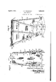
F gure l is a side elevation of an aeroplane showing the brake vconstructediin accordance with'the invention applied and in: braking position.
. Figure 2 is a view simulating. Figure 1 showing the brake in folded or collapsed inactive position. i
Figure 3 is an enlarged front elevationof thebrake in extended braking position.
Figure 4:..is a sectional view on'the 'lineso being broken away for disclosing adjunct, 90.
details.
' Similar: reference characters indicate cor-.
responding parts throughout the several viewsin the drawings- I Referring to the drawings in detail A'des ignates generally the body or fuselage of an. aeroplane which may be ofany standard con- 7 struction having'at its nose or front end the propeller Bwhich gives flight thereto. Upon the body or fuselage A is carriedthe brake 9 constituting the present invention and hereinafter fully described.
The brake comprises a series of bows 10, 11 and 12 respectively, these being suitably fitted in socketed extensions 13 of pivot eyes or cars 14. The bow has its pivot eyes or ears 14 swingingly connected by pivots 15 to outwardly extending lugs 16 on the pivot eyes or ears at their socketed extensions carrying the how 11 and its eyes or ears are swingingly connected by a pivot 17 and offsets 18 tangentially disposed and each formed upon a rotatable disk-like hinge 19, the latter being supported and eccentrically movable upon a pivot 20 of a bearing 21, there being a pair of these. The bearings 21 are rigidly carried by the frame structure of the fuselage or body A and project through the top thereof rearwardly of the location of the pilot or cockpit. Each hinge 19 is provided with an arcuate-shaped slot 22 extending a distance from its center and receives the pivot 20 so that the hinge in the movement thereof has an eccentric motion. The bow 12 has each of its pivot eyes or cars swingingly connected by a pivot 23 eccentrically arranged on the hinge 19 rearwardly of and spaced from the offsets 18 thereof, the pivotal mounting of the bows 10, 11 and 12 being shown in detail in Figure 4 of the drawings.
Carried by the bows 10, 11 and 12 is a collapsible and extensible canopy 24 open at its front and closed at its rear, the lower edges of the sides 25 and rear wall 26 respectively being made fast to the body or fuselage A through the medium of fasteners 27 and angle strips 28, the latter being secured in any suitable manner to said body or fuselage. The bows 10, 11 and 12 are preferably fitted in easements 29 formed in the top 30 and upper portions of the sides 25 of the canopy 24, these easements 29 joining the canopy with said bows in a manner to permit the collapsing or extending of the canopy with the bows when in position for extending such canopy to hold the same taut and in a position for the pocketing of air admitted through its open front.
Suitably arranged and supported within the cockpit or at aconvenient point within the body or fuselage A for access by the pilot or operator of the aeroplane is a hand operated turning wheel 31 having at its periphery the equi-distanced radially projected handles 32 and the axle 33 of this wheel is suitably journaled horizontally and has fixed thereto a drum or Windlass 34 about whichare trained cables 35 and 36 respectively, these being adapted to be wound upon and unwound from such Windlass or drum, the cable 35 having connection 37 with the how 10 and is extended over a guide 38 forwardly of the canopy 24, while the cable 36 is of duplex character and is carried rearwardly through the body or fuselage A thence upwardly, being suitably guided in this direction over the top 30 of the canopy 24 and has attachment at 38 with the bow 10 at opposite sides of the connection 37 and on manipulating the wheel 31 the canopy 24 can beraised for the extension thereof into braking position and also lowered to folding or collapsed position, the extended braking position being shown in Figure 1 while the collapsed or folding position is shown in Figure 2 of the drawings.
The axle 33 of the wheel 31 carries a cog gear 39 with which is engageable a latching dog 40 supported upon a pivot 41 and held in latching position through the medium of a coiled tensioning spring 42 so that the drum or Windlass 34 will be locked against rotation until released by the dog 40. The dog 40 is releasable by a foot pedal 43 having the connection 44 therewith and this pedal 43 is conveniently located relative to the wheel 31 so that the pilot or operator of the aircraft will have perfect control of the brake and the canopy 24 thereof can be raised and lowered or extended or collapsed with dispatch.
It should be apparent that when the canopy 24 is raised or extended for braking position air currents will be pocketed thereby as the air in the line of flight of the aeroplane will be subjected to a back pressure and thus the speed of flight of the plane will be interrupted and such plane caused to descend for a safe landing thereof and within a small area or space. The pocketed air by the brake will balance the aeroplane and give the same a sufiicient lift to prevent sudden dropping or crashing of the plane to earth or the ground. Also the brake by the construction hereinbefore described will avoid a tail-spin, of the aeroplane or the turning over thereof under the braking action when in flight. The speed of flight of course is controllable by the pilot or operator of the machine through the motor of such plane.
It also will be apparent that when the canopy 24 is folded or collapsed the bows 10, 11 and 12 through the pivotal connection there.- of and the hinges willswing into compact relation to each other and become lowered with respect to the body or fuselage A of the aircraft, the position of such bows being shown in Figure 2 of the drawings when the canopy 24 is folded or collapsed.
The canopy 24 can be made from any suit.- able material, of a quality and character to sustain the air impact as will be imposed thereon when in braking position.
What is claimed is 1. In an aeroplane, a fuselage, bearings upon the fuselage and extended upwardly therefrom, rotatable disk-like hinges eccentrically pivoted to the bearings, a plurality of bows, pivots eccentrically connecting certain of the bows with the hinges, means pi'votally offsetting the remaining bow and connecting the same with one of the bows eccentrically pivoted to the hinges,'a canopy car:
ried by the bows andvfixed to'the fuselage to present an open front, closed sides,top and back WlHdlD and unwindin means within the fuselage, and cables carried by said means and connected with the foremost, bow :to per-.
mit raising and lowering of all the bows and imparting eccentric movement tothe hlnges. 2; In an aeroplane, a fuselage, bearings upon the fuselage and extended upwardly and back, winding and unwinding means 7 within the fuselage, cables carried by said 7 therefrom, rotatable V disk-like hinges eccentrically pivoted to the bearings, a plurality of bows, pivots eccentrically connecting certain of thebows with the hinges, means pivotally offsettingthe remaining bow and connectingthe same with one of the bows eccentrically pivoted to the hinges, a'canopy carried by the bows and fixed to the-fuselage to present an open, front, closed sides, top
means and connected with theforemost bow to permit raising andlowering of all the bows and imparting, BCCGIltIlO movement to I the hinges, and means for latching the last named means and foot controlled.
3.. In ancaeroplane, a fuselage, bearings upon the fuselage and extended upwardly therefrom, rotatable disk-like hingeseccentrically pivoted to the bearings, a plurality of bows, pivots eccentrically connecting certainof the bows with the hinges, means pivotally offsetting the remaining bow and con necting the same with one of the bows eccentrically pivoted to the hinges,a canopy carried by the bows and fixed to the fuselage to present an open front, closed sides, top and back, winding and unwinding means within the fuselage, cables carried by said means and connected with'the foremost bow to permit raising and lowering of all the bows and imparting eccentric movement to the hinges, means for latching the last named means and foot controlled, and means for imparting movement to the first named means on release thereof.
In testimony whereof I afiix-my signature.
ANDREW R. BAGGARLY.
Priority Applications (1)
| Application Number | Priority Date | Filing Date | Title |
|---|---|---|---|
| US569762A US1852912A (en) | 1931-10-19 | 1931-10-19 | Aeroplane brake |
Applications Claiming Priority (1)
| Application Number | Priority Date | Filing Date | Title |
|---|---|---|---|
| US569762A US1852912A (en) | 1931-10-19 | 1931-10-19 | Aeroplane brake |
Publications (1)
| Publication Number | Publication Date |
|---|---|
| US1852912A true US1852912A (en) | 1932-04-05 |
Family
ID=24276750
Family Applications (1)
| Application Number | Title | Priority Date | Filing Date |
|---|---|---|---|
| US569762A Expired - Lifetime US1852912A (en) | 1931-10-19 | 1931-10-19 | Aeroplane brake |
Country Status (1)
| Country | Link |
|---|---|
| US (1) | US1852912A (en) |
-
1931
- 1931-10-19 US US569762A patent/US1852912A/en not_active Expired - Lifetime
Similar Documents
| Publication | Publication Date | Title |
|---|---|---|
| US2940688A (en) | Roadable aircraft and sailboat | |
| US3003717A (en) | Flying landing platform | |
| US4165846A (en) | Convertible airplane | |
| US3410506A (en) | Extensible rotor airplane | |
| US3869103A (en) | Retraction system for double pod air cushion landing gear system | |
| US1568765A (en) | Helicopter | |
| US1852912A (en) | Aeroplane brake | |
| US1819794A (en) | Aeroplane | |
| US2837300A (en) | Vertical and horizontal flight aircraft | |
| US2525844A (en) | Parachute for aerodynamic braking of airplanes | |
| US1545553A (en) | Driving plane | |
| US1501530A (en) | Airplane | |
| US1977392A (en) | Aircraft | |
| US2170958A (en) | Power soarer | |
| US1771053A (en) | Low-resistance aeroplane | |
| US2198893A (en) | Aircraft | |
| US2384997A (en) | Braking device for airplanes | |
| US1583745A (en) | Safety attachment for airplanes | |
| US1866451A (en) | Collapsible pontoon for flying machines | |
| US1297604A (en) | Aeroplane. | |
| US1691709A (en) | Safety device for aeroplanes | |
| US1544190A (en) | Semiaero dirigible | |
| US1818067A (en) | Aeroplane | |
| US1631187A (en) | Aeroplane | |
| US1379390A (en) | Aeroplane |