US18528A - Machine fob making brushes - Google Patents
Machine fob making brushes Download PDFInfo
- Publication number
- US18528A US18528A US18528DA US18528A US 18528 A US18528 A US 18528A US 18528D A US18528D A US 18528DA US 18528 A US18528 A US 18528A
- Authority
- US
- United States
- Prior art keywords
- needle
- wire
- brush
- hair
- machine
- Prior art date
- Legal status (The legal status is an assumption and is not a legal conclusion. Google has not performed a legal analysis and makes no representation as to the accuracy of the status listed.)
- Expired - Lifetime
Links
- 210000000080 chela (arthropods) Anatomy 0.000 description 2
- 230000037431 insertion Effects 0.000 description 2
- 238000003780 insertion Methods 0.000 description 2
- 239000002184 metal Substances 0.000 description 2
- 239000002023 wood Substances 0.000 description 2
- 238000010586 diagram Methods 0.000 description 1
- 235000015250 liver sausages Nutrition 0.000 description 1
- 230000001105 regulatory effect Effects 0.000 description 1
- 238000005201 scrubbing Methods 0.000 description 1
Images

Classifications
-
- A—HUMAN NECESSITIES
- A46—BRUSHWARE
- A46D—MANUFACTURE OF BRUSHES
- A46D3/00—Preparing, i.e. Manufacturing brush bodies
- A46D3/04—Machines for inserting or fixing bristles in bodies
- A46D3/05—Machines for inserting or fixing bristles in bodies for fixing the bristles between wires, tapes, or the like
Definitions
- the nature of my invention consists in constructing a machine for wiringand sticking the tufts of hair or bristles 1n clothes, scrubbing and other brushes having wood or metal tuft holder stocks or backs, by means of a wire carrying needle operated by a crank, or cam, and having an intermit of motion at each end of the stroke of the needle for allowing time for inserting the tuft of hair in the loop of the wire, and the feed motion of the brush;
- second a wire holder grips or pincers, and gripping bar, having areciprocating motion at right angles to the vertical motion of the needle for the purpose of carrying the wire to the needle and for taking up the slack of the w1re to draw the tuft of hair in the brush stock;
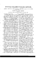
- Figure 1 is an end view of the machine.
- Fig. 2 is a longitudinal out section through the line .00, 00 Fig. 4.
- Fig. 3 is a transverse cut section through the line 10 m Fig. 4:.
- Fig. 4 is a plan of the table board and feed motion.
- Fig. 5, is a diagram of the needle and grippers, with connection for operating the same.
- Letter A is the frame of the machine, which may be made of wood or metal as circumstances may require
- B is the main driving shaft, secured in suitable bearings across the frame of the machine, and below or under the table board (1?.
- On the main shaft is a small cog wheel O, which gears into a second and larger cog wheel D, on a crank shaft E, secured in suitable bearings gether, to give vertical 'motion to the needle K, attached to the head of the needle bar, by means of adjusting screws for regulating its length of stroke.
- This needle bar is secured by suitable guide ways L, attached to the frame of the machine, so as to keep it steady and in its vertical motion in carrying the wire to and from the brush.
- Letter M is a miter cog wheel, also on the crank shaft E, which gears into a second horizontal miter cog wheel N, onthe lower end of a vertical crank shaft P, having a connecting rod Q, attached thereto at one end and the opposite to the end of a horizontal sliding bar R, secured to the under side of the table board of the machine, in suitable guide ways.
- a bracket or clasp S Secured to the back end of this bar, is a bracket or clasp S, into which are inserted, parallel with the bar, the ends of a pair of pincers or wire grippers T, through the jaws of which the wire passes and is fed up to the needle as required for holding the tufts or knots of hair.
- the bracket attached thereto slips forward till it comes against the back of the aws of the grippers, to carry them forward, to slack up the wire as the needle ascends; but is held from opening, in consequence of thin arms pressing against the lower surface of the table board, and a shoulder on the lower side of the sliding bar, till they are carried past a notch plate U, secured to the under side of the table board, when the upper arm of the grippers, opens into a recess and comes to a stop, to allow the jaws to open, and the needle to take up the requisite amount of wire from the spool V.
- this loop former is to open the wire from the sides of the needle, and thereby facilitate the insertion of the knot of hair.
- a Letter Z is a carriage for carrying the brush, arranged to work in guide ways Z on the upper side of the table board and having on its side a rack into which a pawl 6 is made to operate by means of a lever and cam 61 on the vertical crank shaft P, so that at each time the shaft P, rotates it causes the pawl to move the brush, (secured on the carriage by suitable clamps 6 one hole forward for the passsage of the needle to form a new knot or tuft in the brush.
- loop former W operated by means substantially as described, in combination with the needle for the purposes hereinbefore set forth.
Landscapes
- Engineering & Computer Science (AREA)
- Manufacturing & Machinery (AREA)
- Sewing Machines And Sewing (AREA)
Description
L, A. TRIPP.
Making Brushes.
Pate nted Oct. 27, 1857,
Lithographer, Washington D. c,
UNITED STATES PATENT OFFICE.
LEE-MON A. TRIPP, OF NEW YORK, N. Y., ASSIGNOR TO LEIVIS O. PLAT'I, OF WVESTGHESTER COUNTY, NEW YORK.
MACHINE FOR MAKING BRUSHES.
Specification oftLetters Patent No. 18,528. dated October 27, 1857.
To all whom it may concern:
Be it known that I, LEEMoN A. TRIPP, of the city, county, and State of New York, have invented certain new and useful Improvements in Machinery for Making Brushes; and I do hereby declare the following to be a full description of. the same.
The nature of my invention consists in constructing a machine for wiringand sticking the tufts of hair or bristles 1n clothes, scrubbing and other brushes having wood or metal tuft holder stocks or backs, by means of a wire carrying needle operated by a crank, or cam, and having an intermit of motion at each end of the stroke of the needle for allowing time for inserting the tuft of hair in the loop of the wire, and the feed motion of the brush; second, a wire holder grips or pincers, and gripping bar, having areciprocating motion at right angles to the vertical motion of the needle for the purpose of carrying the wire to the needle and for taking up the slack of the w1re to draw the tuft of hair in the brush stock; third, a loop former, operated by a cam on the needle bar crank shaft for opening the wire at the point of the needle, to allow the tuft of hair to be inserted therein and lastly by the combination of a carriage for carrying the brush stock, with the needle, so that the needle will enter each hole in the stock in succession at the required time,all the said foregoing parts being operated automatically by cranks or cams, and cog wheels driven by a main shaft. But to describe my invention more particularly I will refer to the accompanying drawings forming a part of this specification, the same letters of reference wherever they occur referring to like parts. 7
Figure 1, is an end view of the machine. Fig. 2, is a longitudinal out section through the line .00, 00 Fig. 4. Fig. 3, is a transverse cut section through the line 10 m Fig. 4:. Fig. 4, is a plan of the table board and feed motion. Fig. 5, is a diagram of the needle and grippers, with connection for operating the same.
Letter A, is the frame of the machine, which may be made of wood or metal as circumstances may require, and B, is the main driving shaft, secured in suitable bearings across the frame of the machine, and below or under the table board (1?. On the main shaft is a small cog wheel O, which gears into a second and larger cog wheel D, on a crank shaft E, secured in suitable bearings gether, to give vertical 'motion to the needle K, attached to the head of the needle bar, by means of adjusting screws for regulating its length of stroke. This needle bar is secured by suitable guide ways L, attached to the frame of the machine, so as to keep it steady and in its vertical motion in carrying the wire to and from the brush. At each end of the stroke of the needle it is allowed to come to a stop, or remain stationary long enough to allow the loop of wire to be formed, and insertion of the tuft or knot of hair, when the needle is up, and of the feed of the brush stock, when the needle is down, by means of the slot in the end of the rod G, working loosely on the pin I, in the needle bar, during a portion of the rotation of the crank shaft. As this intermit of motion in the needle is of great importance in brush making, I esteem it a very essential feature of my invention, and desire to claim it as necessary to the successful working of this part of the same.
Letter M, is a miter cog wheel, also on the crank shaft E, which gears into a second horizontal miter cog wheel N, onthe lower end of a vertical crank shaft P, having a connecting rod Q, attached thereto at one end and the opposite to the end of a horizontal sliding bar R, secured to the under side of the table board of the machine, in suitable guide ways. Secured to the back end of this bar, is a bracket or clasp S, into which are inserted, parallel with the bar, the ends of a pair of pincers or wire grippers T, through the jaws of which the wire passes and is fed up to the needle as required for holding the tufts or knots of hair. These wire grippers are held loosely in the bracket of the sliding bar, and their operations is thus: When the sliding bar draws back to the end of the stroke of the crank P, the brackets slip back on the arms of the grippers, thereby closing its jaws to hold the wire, and draw the tuft or knot of hair into the hole of the brush stock. On the return or forward stroke of the sliding bar, the bracket attached thereto, slips forward till it comes against the back of the aws of the grippers, to carry them forward, to slack up the wire as the needle ascends; but is held from opening, in consequence of thin arms pressing against the lower surface of the table board, and a shoulder on the lower side of the sliding bar, till they are carried past a notch plate U, secured to the under side of the table board, when the upper arm of the grippers, opens into a recess and comes to a stop, to allow the jaws to open, and the needle to take up the requisite amount of wire from the spool V. At this point they remain at rest long enough for the loop of wire to be formed, and the sliding bar to draw back, till the bracket on it closes the arms of the grippers to grip the wire, and take it out of the notch V, when it is carried back to the end of the stroke to draw the tuft or knot of hair into the hole of the stock. Letter W, a loop-former, ar-
' ranged so as to work horizontally in slide ways on the upper side of the table board, and operated by a lever X, and cam Y, on the crank shaft E. The object of this loop former is to open the wire from the sides of the needle, and thereby facilitate the insertion of the knot of hair.
a Letter Z, is a carriage for carrying the brush, arranged to work in guide ways Z on the upper side of the table board and having on its side a rack into which a pawl 6 is made to operate by means of a lever and cam 61 on the vertical crank shaft P, so that at each time the shaft P, rotates it causes the pawl to move the brush, (secured on the carriage by suitable clamps 6 one hole forward for the passsage of the needle to form a new knot or tuft in the brush.
Having now described my invention and its operations I will proceed to state what I claim and desire to secure by Letters Patent of the United States:
1. I claim the use of the slot H, or equivalent therefor, in the connecting rod G, in combination with the needle, for causing it to remain stationary at each end of the stroke of the crank a definite space of time for the purposes hereinbefore set forth.
2. I also claim the use of the sliding bar R, having a bracket S, attached thereto, in combination with grippers T, operated by the devices hereinbefore described, or equivalent therefor, for the purposes substantially as set forth.
3. I also claim the loop former W, operated by means substantially as described, in combination with the needle for the purposes hereinbefore set forth.
LEEMON A. TRIPP.
Witnesses:
CHARLEY S. BARRITT, H. S. LINCOLN.
Publications (1)
| Publication Number | Publication Date |
|---|---|
| US18528A true US18528A (en) | 1857-10-27 |
Family
ID=2081921
Family Applications (1)
| Application Number | Title | Priority Date | Filing Date |
|---|---|---|---|
| US18528D Expired - Lifetime US18528A (en) | Machine fob making brushes |
Country Status (1)
| Country | Link |
|---|---|
| US (1) | US18528A (en) |
-
0
- US US18528D patent/US18528A/en not_active Expired - Lifetime
Similar Documents
| Publication | Publication Date | Title |
|---|---|---|
| US18528A (en) | Machine fob making brushes | |
| US10528A (en) | Lteistt office | |
| US409830A (en) | Wire-stitching machine | |
| US843487A (en) | Machine for threading and unthreading lace-machine carriages. | |
| US21222A (en) | Hail-plate feeder | |
| US15756A (en) | Method of feeding and sawing shingles | |
| US18268A (en) | John humphrey | |
| US188629A (en) | Improvement in grain-binders | |
| US17183A (en) | Method oe reversing the chisels oe moutisiwo-machines | |
| US172103A (en) | Improvement in machines for stringing tags | |
| US85206A (en) | Improved machine for pegging shoes | |
| US1175290A (en) | Broom-sewing machine. | |
| US11581A (en) | Improvement in clamps for sewing-machines | |
| US618798A (en) | Broom-sewing machine | |
| US340578A (en) | Machine for making looped-wire staples | |
| US10422A (en) | Mortising-machine | |
| US11114A (en) | Cut-nail machine | |
| US17906A (en) | Shingle-machine | |
| US1134721A (en) | Fringe-knotting machine. | |
| US17760A (en) | File-cutting machine | |
| US71852A (en) | chandler | |
| US15913A (en) | Simon ingersoll | |
| US97856A (en) | Improvement in button-holing attachment for sewing-machines | |
| US296628A (en) | Machine for making barbed staples | |
| US13535A (en) | Spike-machine |