US1852899A - Double pole electric switch - Google Patents
Double pole electric switch Download PDFInfo
- Publication number
- US1852899A US1852899A US476917A US47691730A US1852899A US 1852899 A US1852899 A US 1852899A US 476917 A US476917 A US 476917A US 47691730 A US47691730 A US 47691730A US 1852899 A US1852899 A US 1852899A
- Authority
- US
- United States
- Prior art keywords
- switch
- contact
- contact strips
- normally
- double pole
- Prior art date
- Legal status (The legal status is an assumption and is not a legal conclusion. Google has not performed a legal analysis and makes no representation as to the accuracy of the status listed.)
- Expired - Lifetime
Links
- 239000000463 material Substances 0.000 description 12
- 239000011810 insulating material Substances 0.000 description 4
- 229920001342 Bakelite® Polymers 0.000 description 2
- 239000004637 bakelite Substances 0.000 description 2
- 238000010276 construction Methods 0.000 description 2
- 241001274613 Corvus frugilegus Species 0.000 description 1
- 229920001875 Ebonite Polymers 0.000 description 1
- 241001080526 Vertica Species 0.000 description 1
- 238000005452 bending Methods 0.000 description 1
- 230000000994 depressogenic effect Effects 0.000 description 1
- 239000000835 fiber Substances 0.000 description 1
- 230000006872 improvement Effects 0.000 description 1
- 230000001788 irregular Effects 0.000 description 1
- 229920000136 polysorbate Polymers 0.000 description 1
- 229910052573 porcelain Inorganic materials 0.000 description 1
- 230000008092 positive effect Effects 0.000 description 1
Images
Classifications
-
- H—ELECTRICITY
- H01—ELECTRIC ELEMENTS
- H01H—ELECTRIC SWITCHES; RELAYS; SELECTORS; EMERGENCY PROTECTIVE DEVICES
- H01H23/00—Tumbler or rocker switches, i.e. switches characterised by being operated by rocking an operating member in the form of a rocker button
- H01H23/02—Details
- H01H23/12—Movable parts; Contacts mounted thereon
- H01H23/16—Driving mechanisms
- H01H23/162—Driving mechanisms incorporating links interconnecting tumbler and contact arm
Definitions
- This invention relates to electricswitches and more particularly it relates to: a double pole electric'switch of the lever type.
- Actuating mechanism is then provided for simultaneously,connecting each negative contact plate with its corresponding positive. This connection is usually made-by a pivoted contact arm.
- the present invention obviates the disad vantages recited as well as other disadvane tages present in the prior art. It introduces anew switch which in many respects'is a radical departure from-that which has preceded it:
- the present invention is in'etfect', an innovation in switch design andconst'ruction'.
- One of the objects otthis'invention' is to provide a double pole electric switch of the lever type in which positiveand negative contact strips are disposed at each end-within the casing.
- Another object of this invention is the provisioniot a novel means simultaneously making or breaking contact between the negative and positive contact strips at each end of the casing.
- Still a further object of this invention is the provision ofan insulating member to make and break thecircuits and an actuatingmechanism therefor which has apositive start and a spring finish.
- this invention contemplates a switch whichwhile meetingthe requirements ofunderwriters," may be easily and inexpensively manufactured of a few simpleparts.
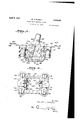
- Fig. 1 is aside elevation View of the switch with a portion of the casing removed to disclose the actuating mechanism.
- F ig; 2- is a plan view of the casingpwith the actuating mechanism removed to showthe positioning of the contact strips.
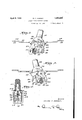
- Fig. 3 is a side elevation view of theactu ating'; mechanism as it appears when the switchisin-open-position. One of the side plates is cut away to more clearly show the inner mechanism. 7
- Fig. 4 is a viewsimil'ar to y that shown in Fig; 3, butishowing the actuating mechanism asit appears when the switchisin closed po sition'.
- Fig. 5" is'a sectional end view ofthe' mecha' nism' and the actuating lever when the latter is substantially in vertica'l'position:
- the switch. shown is of the fiush-typeand lsadapted tobe inserted in a wall recess in the ,wellknown fashion, and to be covered 7 With a' plate (not'shown) having a central re cess therein to allow the actuating-lever to protrude therethrough.
- the switch is comprisedof'a base portion or casinglO of porcelain, bakelite, or other suitableinsulating material.
- This casing is provided withan interiorchamber 12 opening at the top and houses the contact strips and actu ating mechanism to be later described;
- the terminal plates are secured to thecasing by means-otscrews 18 and the terminal posts are threaded to be received by-threaded recesses in the ter minal plates and inthe ledge portions direct I 1y therebelow;v Contrary to the usual arrangement, the terminal posts 16 at each end of the casing "are attached to negative and positive wires (not shown) so that each end of the switch will have a negative anda positive terminal post.
- contact-strips 20, 22 and 24 26 which extend downwardly along the end walls of the interior chamber 12.
- the contact strips are of spring material and two of them 20, 22 converge downwardly so that their lowermost positions meet to form an electrical connection.
- the spring material of which they are constructed acts to press these contactstrips and 22 in a normally contacting position.
- the oppositely disposed contact strips 24 and 26 also converge but their lowermost portions normally remain separated.
- a vertical groove 28 is out centrally in each end wall of the interior chamber 12 and extends partially along the fioor thereof.
- the actuating mechanism is shown in Flg. 1 as being housed in the interior chamber 12 of the casing 10. It is comprised of a supporting bar 30 which is removably secured to the top of the casing by means of screws 32 lodged in vertical bores in the ends of the casing.
- the cars 34 of the supporting bar 30 are provided with apertures 36 through which screws may be passed to secure the switch in a wall recess in the conventional manner.
- the supporting bar extends across the open face of the interior chamber 12 at which point the bar is cut out to provide an opening for the operating lever 38.
- side plates or wings 40 which are preferably integral with the supporting bar and form therewith a supporting frame in which the actuating mechanism proper is mounted.
- the switch is operated by the lever 38 and is provided with an arrangement whereby the circuit is broken or made by a snap movement start, a kick off, and a spring finish.
- this movement is well known in the art, but the present invention also includes several novel features and a new arrangement of the operative elements.
- a rectangular frame portion 42 is provided with a projecting member 44 which extends within the operating lever 38.
- the operating lever is of hard rubber, bakelite, or other suitable insulating material and the projecting member 44 is preferably inserted in the lever when the latter is moulded into form.
- the rectangular frame portion is thus effectively secured to the operating lever so as to be integral therewith.
- the lower edges of the side plates 40 are arcuate and have downwardly projecting portions 46 at each end.
- the upper edges of these side plates 40 are provided with irregular shaped cut-out portions 48. From 5 it will be apparent that these cut-out portions 148 permit the rectangular frame 42 to he slipped into position over the end of the supporting bar 30 and the side plates 40. In operative position the upper portion of the rectangular frame rests in-the the reference numeral 50,
- the actuating lever 38 and its integral rectangular frame portion 42 may now rook back and forth, the recess acting as a pivot point therefor.
- rocker member 54 which is substantially in the form of an ini erted U. This member is of a width slightly less than the distance between the side plates 40 and is provided with outwardly and upwardly extending arms 56 of spring material.
- the lower ends of the side portions of the rocker member 54 have slots 58 cut therein which engage pivot pins 60 projecting inwardly from the side plates 40.
- the rocker member 54 is effectively limited in this movement by the stop pins 62 which also project inwardly from the side plates 40.
- An arcuate circuit maker and breaker of insulating material such as a stiff fibre is indicated by the reference numeral 64.
- an apertured downwardly projecting center piece 70 (shown in dotted lines) which projects through a cut-out portion 72 in the top of the rocker member 54 to be engaged by the main coil spring 74.
- the opposite end of the coil spring is secured to the central portion of the base of the rectangular frame 42, a notch 7 6 being provided to keep the spring in place.
- the arcuate member 64 is also held in vertical position by a groove 7 8 cut in the rectangular frame and by grooves 80 in the arms 56 of the rocker member 54.
- the arm 68 of the arcuate member is provided with a contact stud 82 which passes therethrough.
- Fig. 1 the switch is shown in open position.
- the contact strips 24 and 26 are in their normally separated position and the arm 66 of the arcuate member 64 is lodged between the contact strips 20 and 22 to prevent them from assuming their normally contacting position.
- the switch described is characterized by its simplicity of construction, its relatively few ports, and its positive action.
- The-use of pairs of negative and positive contact strips, one of which is normally in closed position and the other being normally in spaced position, and the use of the arcuate arm of insulating material not only make possible the construction of a superior switch but obviate the disadvantages which usually accom' pany double pole switches of the lever type.
- pole flush switch comprising Patent of the United 1.
- a double a casing spring material disposed at one end of the interior chamber, a pair of normally spaced contact strips of spring material disposed at theother end of said interior chamber, and
- actuating means housed within said interior nonconducting material having a contact stud on one end thereof, means to actuate said member of nonconducting material, said member in one position adapted to separate said pair of normally contacting contact having an interior chamber, a pair of normally contacting contact strips of strips, and in another position to be with drawn frombetween said normally contact ing contact strips and to be thrust between said normally spaced contact strips, said" contact stud forming a connection therebe tween.
- a switch comprising a pair of normally contacting contact strips, a pairof normallyspaced contact strips, a member of 1nsulating material a contact stud on one end contact stud in one position adapted to connect said normally spaced contact strips, and means to actuate said member of insulating material to withdraw said contact stud from between said normally spaced contact strips and to thrust the other end of said member between said normally spaced contact strips to break the connection therebetween.
- a double pole flush switch comprising a casinghaving an interior chamber, a pair of normally contacting contact strips of spring material disposed at one end of the interior chamber, a pair of normally spaced contact strips of springmaterial disposed at the other end "of said interior chamber,
- said actuating mechanism comprising an arcuate member of nonconducting. material, a contact stud passing through one end of said arcuate member, and means to actuate said arcuate member either to assume a position in which the said contact stud connectssaid normally spaced contact strips, the other contact strips remaining normally in contacting position, or to assume a position in which the contact stud is withdrawn from between said normal1y spaced. contact strips and the opposite end of the arcuate member is lodged between to separate them.
Landscapes
- Push-Button Switches (AREA)
Description
' April 5, 1932.
w. F. RAMSAY DOUBLE POLE ELECTRIC SWITCH 2 Sheets-Sheet Filed Aug. 21, 1930 Jwwntoc MJAK A ril 5, 1932. w. F. RAMSAY 1,852,899
DOUBLE POLE ELECTRIC SWITCH Filed Aug. 21, 1930 2 Sheets-Sheet 2 F JWMM Wax/4M f. films/1K;
PatentedApr. 5, .1932.
WILLIAM. J3. RAMSAY," or: HARTFORD, CONNECTICUT DOUBLE. POLE ELECTRIC; swIrcH.
Application fi1ed.August.21, 1930. Serial no 476317;
' This invention: relates to electricswitches and more particularly it relates to: a double pole electric'switch of the lever type.
In switches of this generaltype it has hitherto been the practice to haveboth negative contact plates arranged atone end within a casingand their corresponding positive contact plates disposed :atthe opposite, end;
Actuating mechanism is then provided for simultaneously,connecting each negative contact plate with its corresponding positive. This connection is usually made-by a pivoted contact arm. The disadvantages accompany,-
ing a switch constructed as describedare numerous. One of the greatest of these disadvantagesis the necessity for insulating means to separate the contact strip from the actuat= ing mechanism to prevent possible short circuits; Such a switch also requires a considerable'number of parts which, of'course, add to the cost and clifliculty of manuta'cture.
The present invention obviates the disad vantages recited as well as other disadvane tages present in the prior art. It introduces anew switch which in many respects'is a radical departure from-that which has preceded it: The present invention is in'etfect', an innovation in switch design andconst'ruction'.
One of the objects otthis'invention' is to provide a double pole electric switch of the lever type in which positiveand negative contact strips are disposed at each end-within the casing.
Another object of this invention is the provisioniot a novel means simultaneously making or breaking contact between the negative and positive contact strips at each end of the casing.
Still a further object of this invention is the provision ofan insulating member to make and break thecircuits and an actuatingmechanism therefor which has apositive start and a spring finish.
As a further object this invention contemplates a switch whichwhile meetingthe requirements ofunderwriters," may be easily and inexpensively manufactured of a few simpleparts.
These and other obj ects" will become more for positively and 1 y are located on depressed ledges at the-four apparent from the following description when read in conjunction with the accompa= nying-drawingsand the appended claims;
In the drawings:
Fig. 1 is aside elevation View of the switch with a portion of the casing removed to disclose the actuating mechanism.
F ig; 2- is a plan view of the casingpwith the actuating mechanism removed to showthe positioning of the contact strips.
Fig. 3 is a side elevation view of theactu ating'; mechanism as it appears when the switchisin-open-position. One of the side plates is cut away to more clearly show the inner mechanism. 7
Fig. 4 is a viewsimil'ar to y that shown in Fig; 3, butishowing the actuating mechanism asit appears when the switchisin closed po sition'.
Fig. 5"is'a sectional end view ofthe' mecha' nism' and the actuating lever when the latter is substantially in vertica'l'position: The switch. shown is of the fiush-typeand lsadapted tobe inserted in a wall recess in the ,wellknown fashion, and to be covered 7 With a' plate (not'shown) having a central re cess therein to allow the actuating-lever to protrude therethrough.
Referring first to Figs. 1'and 2; the switch is comprisedof'a base portion or casinglO of porcelain, bakelite, or other suitableinsulating material. This casing is provided withan interiorchamber 12 opening at the top and houses the contact strips and actu ating mechanism to be later described;
Secured to theterminal plates 14 are. contact- strips 20, 22 and 24 26 which extend downwardly along the end walls of the interior chamber 12. The contact strips are of spring material and two of them 20, 22 converge downwardly so that their lowermost positions meet to form an electrical connection. The spring material of which they are constructed acts to press these contactstrips and 22 in a normally contacting position.
The oppositely disposed contact strips 24 and 26 also converge but their lowermost portions normally remain separated.
A vertical groove 28 is out centrally in each end wall of the interior chamber 12 and extends partially along the fioor thereof.
The actuating mechanism is shown in Flg. 1 as being housed in the interior chamber 12 of the casing 10. It is comprised of a supporting bar 30 which is removably secured to the top of the casing by means of screws 32 lodged in vertical bores in the ends of the casing. The cars 34 of the supporting bar 30 are provided with apertures 36 through which screws may be passed to secure the switch in a wall recess in the conventional manner.
The supporting bar extends across the open face of the interior chamber 12 at which point the bar is cut out to provide an opening for the operating lever 38.
:1 having a positive Figs. 1 and Downwardly depending from opposite sides of the mid portion of the supporting bar 30 are side plates or wings 40 which are preferably integral with the supporting bar and form therewith a supporting frame in which the actuating mechanism proper is mounted.
The switch is operated by the lever 38 and is provided with an arrangement whereby the circuit is broken or made by a snap movement start, a kick off, and a spring finish. Generally, this movement is well known in the art, but the present invention also includes several novel features and a new arrangement of the operative elements.
A rectangular frame portion 42 is provided with a projecting member 44 which extends within the operating lever 38. The operating lever is of hard rubber, bakelite, or other suitable insulating material and the projecting member 44 is preferably inserted in the lever when the latter is moulded into form. The rectangular frame portion is thus effectively secured to the operating lever so as to be integral therewith.
The lower edges of the side plates 40 are arcuate and have downwardly projecting portions 46 at each end. The upper edges of these side plates 40 are provided with irregular shaped cut-out portions 48. From 5 it will be apparent that these cut-out portions 148 permit the rectangular frame 42 to he slipped into position over the end of the supporting bar 30 and the side plates 40. In operative position the upper portion of the rectangular frame rests in-the the reference numeral 50,
recess indicated by this position being the rectangular frame in in a plane substantially at right angles to the plane of the side plates. The downwardly projecting arm 52 and the projecting porti ons 46 aid in retaining the rectangular frame in its proper positions. The projections 46 also mark the extreme limits of the traveled path of the frames base.
The actuating lever 38 and its integral rectangular frame portion 42 may now rook back and forth, the recess acting as a pivot point therefor.
Between the side plates or wings 40 is positioned a rocker member 54 which is substantially in the form of an ini erted U. This member is of a width slightly less than the distance between the side plates 40 and is provided with outwardly and upwardly extending arms 56 of spring material.
The lower ends of the side portions of the rocker member 54 have slots 58 cut therein which engage pivot pins 60 projecting inwardly from the side plates 40. The rocker member 54 is effectively limited in this movement by the stop pins 62 which also project inwardly from the side plates 40.
An arcuate circuit maker and breaker of insulating material such as a stiff fibre is indicated by the reference numeral 64. Between its two arms 66 and 68 is an apertured downwardly projecting center piece 70 (shown in dotted lines) which projects through a cut-out portion 72 in the top of the rocker member 54 to be engaged by the main coil spring 74. The opposite end of the coil spring is secured to the central portion of the base of the rectangular frame 42, a notch 7 6 being provided to keep the spring in place. The arcuate member 64 is also held in vertical position by a groove 7 8 cut in the rectangular frame and by grooves 80 in the arms 56 of the rocker member 54.
The grooves 28, shown in Fig. 2 as located in the sides and floor of the interior chamber 12, guide the arcuate circuit maker and breaker in its traveled path.
The arm 68 of the arcuate member is provided with a contact stud 82 which passes therethrough.
The operation of the mechanism to make and break the electrical connections will now be described. In Fig. 1 the switch is shown in open position. The contact strips 24 and 26 are in their normally separated position and the arm 66 of the arcuate member 64 is lodged between the contact strips 20 and 22 to prevent them from assuming their normally contacting position.
When the operating lever 38 is thrust from right to left its movement will first be resisted by the spring coil 74 and by the spring arm 56 of the rocker member 54 which is forced into bending position by the portions 84 (Fig. 5) of the rectangular frame 42. As the coil spring is carried past the pivotpin by the base of the rectangular frame 42, the spring. arm 56 of the rocker member will bend sutticientlyto allow it to snappast the portionsdrawn from between the contact strips 20, 22
allowing them to spring together in their normal contacting position. The other arm 68 of the arcuate member 64 has been thrust between the normally spaced contactstrips 2A and 26 and the contact stud82 acts to com- 'plete the connection between'thenn Both pairs of contact strips are now connected and the switch is in closed position.
'To open theswitch the movement is the same, however, the parts must obviously travel in the opposite direction. I
. The switch described is characterized by its simplicity of construction, its relatively few ports, and its positive action. The-use of pairs of negative and positive contact strips, one of which is normally in closed position and the other being normally in spaced position, and the use of the arcuate arm of insulating material not only make possible the construction of a superior switch but obviate the disadvantages which usually accom' pany double pole switches of the lever type.
It is apparent that these marked improve ments maybe used with equal efiectiveness in a rotary type switch, a switch having three or more poles, and also in a single pole and a three-way switch, and I do not wish to limit myself to the particular embodiment herein disclosed.
Having described my invention, what I claim as new and desire to secure by Letters States is: pole flush switch comprising Patent of the United 1. A double a casing spring material disposed at one end of the interior chamber, a pair of normally spaced contact strips of spring material disposed at theother end of said interior chamber, and
actuating means housed within said interior nonconducting material having a contact stud on one end thereof, means to actuate said member of nonconducting material, said member in one position adapted to separate said pair of normally contacting contact having an interior chamber, a pair of normally contacting contact strips of strips, and in another position to be with drawn frombetween said normally contact ing contact strips and to be thrust between said normally spaced contact strips, said" contact stud forming a connection therebe tween.
3. A switch comprising a pair of normally contacting contact strips, a pairof normallyspaced contact strips, a member of 1nsulating material a contact stud on one end contact stud in one position adapted to connect said normally spaced contact strips, and means to actuate said member of insulating material to withdraw said contact stud from between said normally spaced contact strips and to thrust the other end of said member between said normally spaced contact strips to break the connection therebetween.
4. A double pole flush switch comprising a casinghaving an interior chamber, a pair of normally contacting contact strips of spring material disposed at one end of the interior chamber, a pair of normally spaced contact strips of springmaterial disposed at the other end "of said interior chamber,
and arr-actuating mechanism housed in said interior chamber, said actuating mechanism comprising an arcuate member of nonconducting. material, a contact stud passing through one end of said arcuate member, and means to actuate said arcuate member either to assume a position in which the said contact stud connectssaid normally spaced contact strips, the other contact strips remaining normally in contacting position, or to assume a position in which the contact stud is withdrawn from between said normal1y spaced. contact strips and the opposite end of the arcuate member is lodged between to separate them.
In testimony whereof I have hereunto set I. of said member ofinsulating material, said] f the pair of normally contacting contact strips r
Priority Applications (1)
| Application Number | Priority Date | Filing Date | Title |
|---|---|---|---|
| US476917A US1852899A (en) | 1930-08-21 | 1930-08-21 | Double pole electric switch |
Applications Claiming Priority (1)
| Application Number | Priority Date | Filing Date | Title |
|---|---|---|---|
| US476917A US1852899A (en) | 1930-08-21 | 1930-08-21 | Double pole electric switch |
Publications (1)
| Publication Number | Publication Date |
|---|---|
| US1852899A true US1852899A (en) | 1932-04-05 |
Family
ID=23893778
Family Applications (1)
| Application Number | Title | Priority Date | Filing Date |
|---|---|---|---|
| US476917A Expired - Lifetime US1852899A (en) | 1930-08-21 | 1930-08-21 | Double pole electric switch |
Country Status (1)
| Country | Link |
|---|---|
| US (1) | US1852899A (en) |
Cited By (3)
| Publication number | Priority date | Publication date | Assignee | Title |
|---|---|---|---|---|
| US2807683A (en) * | 1954-10-07 | 1957-09-24 | John I Paulding Inc | Flush switch and casing therefor |
| US2821589A (en) * | 1955-11-29 | 1958-01-28 | Needham Francis Leo | Three-way toggle switch |
| US4297551A (en) * | 1980-03-31 | 1981-10-27 | Ronk Electrical Industries, Inc. | Electrical transfer switch |
-
1930
- 1930-08-21 US US476917A patent/US1852899A/en not_active Expired - Lifetime
Cited By (3)
| Publication number | Priority date | Publication date | Assignee | Title |
|---|---|---|---|---|
| US2807683A (en) * | 1954-10-07 | 1957-09-24 | John I Paulding Inc | Flush switch and casing therefor |
| US2821589A (en) * | 1955-11-29 | 1958-01-28 | Needham Francis Leo | Three-way toggle switch |
| US4297551A (en) * | 1980-03-31 | 1981-10-27 | Ronk Electrical Industries, Inc. | Electrical transfer switch |
Similar Documents
| Publication | Publication Date | Title |
|---|---|---|
| US1852899A (en) | Double pole electric switch | |
| US2540435A (en) | Electric switch | |
| US1956422A (en) | Electric switch | |
| US2277555A (en) | Operating mechanisms for electric switches | |
| US1780684A (en) | Circuit-interrupting device | |
| US1935498A (en) | Lever operated snap switch | |
| US1795434A (en) | Panel-board switch | |
| US2002587A (en) | Electric circuit controlling mechanism | |
| US2215714A (en) | Electrical switch | |
| US1987025A (en) | Electric switch | |
| US1537272A (en) | Safety switch | |
| US2917610A (en) | Electric wiring device | |
| US2190342A (en) | Double break electric switch | |
| US1903180A (en) | Electric switch | |
| US1887274A (en) | Combined switch and circuit breaker | |
| US2120423A (en) | Electric tumbler switch | |
| US1860876A (en) | Electrical switch | |
| US1580663A (en) | Electric wall switch | |
| US1755368A (en) | Electric-circuit-controlling appliance | |
| US2098559A (en) | Safety switch | |
| US1962867A (en) | Dead front safety switch | |
| US2247231A (en) | Electric switch | |
| US1517638A (en) | Electric switch | |
| US1751398A (en) | Electric switch | |
| US1477251A (en) | John e |