US1852889A - Heater - Google Patents
Heater Download PDFInfo
- Publication number
- US1852889A US1852889A US373710A US37371029A US1852889A US 1852889 A US1852889 A US 1852889A US 373710 A US373710 A US 373710A US 37371029 A US37371029 A US 37371029A US 1852889 A US1852889 A US 1852889A
- Authority
- US
- United States
- Prior art keywords
- heater
- pipe
- air
- casing
- inner casing
- Prior art date
- Legal status (The legal status is an assumption and is not a legal conclusion. Google has not performed a legal analysis and makes no representation as to the accuracy of the status listed.)
- Expired - Lifetime
Links
- 238000010276 construction Methods 0.000 description 3
- 239000002184 metal Substances 0.000 description 3
- 229910052751 metal Inorganic materials 0.000 description 3
- PXHVJJICTQNCMI-UHFFFAOYSA-N Nickel Chemical compound [Ni] PXHVJJICTQNCMI-UHFFFAOYSA-N 0.000 description 2
- 230000000284 resting effect Effects 0.000 description 2
- RYGMFSIKBFXOCR-UHFFFAOYSA-N Copper Chemical compound [Cu] RYGMFSIKBFXOCR-UHFFFAOYSA-N 0.000 description 1
- 239000010425 asbestos Substances 0.000 description 1
- 238000002485 combustion reaction Methods 0.000 description 1
- 229910052802 copper Inorganic materials 0.000 description 1
- 239000010949 copper Substances 0.000 description 1
- 230000008878 coupling Effects 0.000 description 1
- 238000010168 coupling process Methods 0.000 description 1
- 238000005859 coupling reaction Methods 0.000 description 1
- 239000000446 fuel Substances 0.000 description 1
- 230000037431 insertion Effects 0.000 description 1
- 238000003780 insertion Methods 0.000 description 1
- 239000000463 material Substances 0.000 description 1
- 229910052759 nickel Inorganic materials 0.000 description 1
- 230000000717 retained effect Effects 0.000 description 1
- 229910052895 riebeckite Inorganic materials 0.000 description 1
Images

Classifications
-
- F—MECHANICAL ENGINEERING; LIGHTING; HEATING; WEAPONS; BLASTING
- F24—HEATING; RANGES; VENTILATING
- F24H—FLUID HEATERS, e.g. WATER OR AIR HEATERS, HAVING HEAT-GENERATING MEANS, e.g. HEAT PUMPS, IN GENERAL
- F24H3/00—Air heaters
- F24H3/006—Air heaters using fluid fuel
Definitions
- My 1 invention consists of an improvement
- heaters especially -for' domestic use, uti- V lizing'an'y suitable fuel as gas or'zoil, capable of flowregulation: It hasin viewto provide a heater or s1mpleandcheap COZlSlLI'LlClJlOIl I fcapable of subjecting upwardly" circulating alr -to the 'radia tedlheat of-a furnace cha1n- 7 her; and havingwthe features of advantage of gutility and economy ashereina fterdescribed.
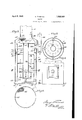
- Fig; l ' is a perspective View showing lnyi improved heater suspended below the floor H grating;
- Fig. 2' is a cross sectionson the line II II Fig. 3zis a vertical sectional vieur 'of the heater 'showing the open bottom air supply j construction;
- F ig. s4 is a bottorn View of the-heater look ⁇ 7 ing upwardly;
- Fig. V5 is a cross section 5011 the line V-Y 7' of the, heater in elevation;
- a delivery conduit'or F ig.” 6 is a f ce' view of the low'er port-ion Figfi? perspective detailview] of the removable coniform dirt collector.
- the heater as a Whole may be cylindrical
- Partitionor shell dextends-from near the bottom of outer shell" 2 to ,.near its -top,.as
- closedbyaremovable dome 12 having a telescoping'u shell extension 13 "fittingbver the top and resting onian der 14 orthelikeQ Q I Dome 12 is redr' ced'indiameter and has an upward extension 15 telescoping into the conduit 16 which conducts air through the grating 5,'as iii-Fig; '1.
- I provide the remov able cone-shaped "collecting; cup or bond s haVingfthe-reduced lower extension 19 rev 7 'mouably fitted into the upper end of the middle pipe 11.;
- the bowl 17 is of wire netting t or perforated metalfor free upward circulation of; hot air, as indicated, and when in? serted 7 there is an upper annular "clearance space 20 :around”"its Op -i 01fthe same purpose .c
- Inner shell. 3 is suspended -Withinfouter c.
- the products of combustion are taken off to a flue or chimney by a pipe having a T connection 31 which, for eas snug fitting insertion and removal, fits etween an outer collar 32 and an inner collar 33 leading outwardly from the shell extension 10a, as shown.
- the T connection 31 may be rotated with section 13 to any desired position, which is highly desirable in installing the heater.
- the lower end 34 of T coupling 31 may be closed at the bottom. or partly open to facilitate the draft of the flue connection.
- I preferably provideinner and outer removable linings 35 236 of nickel, copper, or other resistant material, as shown.
- the bottom of the heater is pref embly covered with a protecting screen 41. of wire netting or the like, as shown in Figs. 3 and 4, and is hinged as at 42 to permit access to the interior of the heater.
- the entire heater may rest on suitable legs or pedestals, or may be bodily suspended from a ceiling or floor beams by wires or chains 39 connected at 40 with the outer casing and diverging upwardly, as in Fig. 1.
- this is an open bottom heater, it is preferably supported from the floor beams as indicated in Fig. 1, to permit a ready circulation of air.
- the cellar or lower room wherein the heater is suspended. aots as a cold air well.
- the heater is lighted. the air in the circulating space 4 becomes heated and passes upwardly through the conduit 16.
- the entire heater may be easily and 'ckly assembled, with facility for remov of the fitting 31, dome 12, or of bowl 17, while the cover 10 may also be readily removed for renewing pipe 11 or for placement or removal of baflles 28.
- I claim 1 In a heater, an inner casing and an outer casing providing an upward passage for air therebetween, a delivery conduit for the outer casing, means closing the top of the mnerca-sing having a pipe depending there from into the inner easing, a receptacle in the upper end of said pipe having a ortion above said means to direct descen 'ng matter into the pipe, said portion being perforated for the passage of heated air therethrough, burner means within the inner casing, and discharge flue means leading from the inner using.
- an inner casing and an outer casing providing an upward passage for air therebetween, a delivery conduit extending from the outer casing, a pipe within the inner casing, said inner casing being closed at the top outwardly of said pi a. receptacle for matter descending throng the delivery conduit, said receptacle being dis- (1 in the upper end of said pipe, burner means within the inner casing, and discharge flue means leading from the inner casing.
- an inner casing and an Outer casing providing an upward passage for air therebetween, said outer casing above the inner casing extending inwardly and terminating in a delivery conduit, a pipe within the inner casing, said inner casing being closed outwardly of the pipe, a receptacle in line with the delivery conduit and retained by the upper end of said pipe, said receptacle having a wall extending upwardly and outwardly below said delivery conduit and of greater diameter than the delivery conduit said wall being perforated for the passage of air therethrough.
Landscapes
- Engineering & Computer Science (AREA)
- Physics & Mathematics (AREA)
- Thermal Sciences (AREA)
- Chemical & Material Sciences (AREA)
- Combustion & Propulsion (AREA)
- Mechanical Engineering (AREA)
- General Engineering & Computer Science (AREA)
- Steam Or Hot-Water Central Heating Systems (AREA)
Description
April 5 1932. H. MCKINNIE 1,852,889;
HEATER Filed June 26, 1929 2 Sheets-Sheet l H. MCKINNIE April 5, 1932.
HEATER Filed June 26, 1929 2 Sheets-Sheet INVENTOR Patented; Apr. 5, *1932f HE R IMcKninI 11 PITTSBURGH, mmmwvrm HEAT 1 I Application f'filed ti e. 26,
My 1 invention consists of an improvement,
in heaters, especially -for' domestic use, uti- V lizing'an'y suitable fuel as gas or'zoil, capable of flowregulation: It hasin viewto provide a heater or s1mpleandcheap COZlSlLI'LlClJlOIl I fcapable of subjecting upwardly" circulating alr -to the 'radia tedlheat of-a furnace cha1n- 7 her; and havingwthe features of advantage of gutility and economy ashereina fterdescribed.
Referring to the drawingsshowing certain preferred constructions;
Fig; l 'is a perspective View showing lnyi improved heater suspended below the floor H grating;
Fig. 2'is a cross sectionson the line II II Fig. 3zis a vertical sectional vieur 'of the heater 'showing the open bottom air supply j construction;
F ig. s4 is a bottorn View of the-heater look} 7 ing upwardly;
Fig. V5 is a cross section 5011 the line V-Y 7' of the, heater in elevation;
' a delivery conduit'or F ig." 6 is a f ce' view of the low'er port-ion Figfi? perspective detailview] of the removable coniform dirt collector.
" The heater as a Wholemay be cylindrical,
square, or of other form, preferably of sheet metal, having an outer casing 2-proyidec with an asbestos lining 2a, and aninner concentric casing 35 with an intervening annular air circulation space 4.
I Invjthe form shownfin'Figel it is designed thatcoldvair from a room or surrounding cavity as a cellar below, may be delivered through annular space 4 upwardly through pipe 16, andv grating to aroom above. v H p f The construction results in preheating the air supplied to theffuelburners;
Partitionor shell dextends-from near the bottom of outer shell" 2 to ,.near its -top,.as
in Fig.8, and is closedby a top 'plateor cover :10, havinga telescoping shell extension 10 g: i iBStlIlg onan expanded ringer shoulder A'central open'conduit inthe form of re movable pipe l l"extendsfromthe top 101a) for nearly to the, bottom ofFinner-casing 3. c'
Theupper open endof Outer'casingQ is course be substituted]. v
1929.. serial No. 373,710.
expandedring or shou'l-a upwardly For-the purpose of protecting against acfi" cumulation of foreign' matter Which may fall I through the Q g, I provide the remov able cone-shaped "collecting; cup or bond s haVingfthe-reduced lower extension 19 rev 7 'mouably fitted into the upper end of the middle pipe 11.; The bowl 17 is of wire netting t or perforated metalfor free upward circulation of; hot air, as indicated, and when in? serted 7 there is an upper annular "clearance space 20 :around""its Op -i 01fthe same purpose .c
Inner shell. 3 is suspended -Withinfouter c.
Wfi ly1'- shell '2' any suitablei manner, secured brackets or clips 21. resting onlugs' ora'butinents22 of the. outer shelhfas showni: i
At its'lo wer end the "inner shell is spaced" from the outer shcll iand held ccntrally by; V
v h acketsee or other suitable spam erg;providing for free u w d qifculvatiponi of inco n's v s a r r v Burners; 245 of anyjsuitable kind Tare 'located mproperfspaced positions around the lower annular space betweencpipe 11 and casg c I p 3 each burner preferably having regu latmg-valVe 25.and:be1ngconnected b'v suit able fittings with a main supply'pipe' 26 c'ofn nected withaimain and having a mi epen-y ing" and closinglxvalve 2' 7.- able l'forlnc or, number of burners may: of
Above the. burn ers5 one, or lnorebafiiesi28 preferably alternating, or the like, are laid across the clrculating area on brackets-129010 the like,-= for retardation or bafllihg zflof the gaseous-flow; and it will; be understood that ny umb r 6 desired Su'clrZba iil's are remoi ably supported on? lugs. or fiangesfextending inwardly from the a i r 10c inner casing; Witlran annular clearance spacef.
Any other suit- 9o 1 sof[perforated+metal, with the ,perforationsl- 9t 7 such baffles"rnay fbe usech as} ill around the outer edges of the metal plates.
The products of combustion are taken off to a flue or chimney by a pipe having a T connection 31 which, for eas snug fitting insertion and removal, fits etween an outer collar 32 and an inner collar 33 leading outwardly from the shell extension 10a, as shown.
It will be noted that due to the shell eX- tensions 10a and 13 being rotatablymovable, the T connection 31 may be rotated with section 13 to any desired position, which is highly desirable in installing the heater. The lower end 34 of T coupling 31 may be closed at the bottom. or partly open to facilitate the draft of the flue connection.
In order to protect those parts of casings 3 and 11 which are exposed to the heat of the burners, I preferably provideinner and outer removable linings 35 236 of nickel, copper, or other resistant material, as shown.
An outer door 37 and an inner slide 38 pzovide for access to the burners, and it will seen that ample air supply thereto is provided, upwardly through the open bottom, as in Fig. 3. The bottom of the heater is pref embly covered with a protecting screen 41. of wire netting or the like, as shown in Figs. 3 and 4, and is hinged as at 42 to permit access to the interior of the heater.
The entire heater may rest on suitable legs or pedestals, or may be bodily suspended from a ceiling or floor beams by wires or chains 39 connected at 40 with the outer casing and diverging upwardly, as in Fig. 1.
As this is an open bottom heater, it is preferably supported from the floor beams as indicated in Fig. 1, to permit a ready circulation of air. To this end, the cellar or lower room wherein the heater is suspended. aots as a cold air well. When the heater is lighted. the air in the circulating space 4 becomes heated and passes upwardly through the conduit 16.
It will be observed from the foregoing description that the entire heater may be easily and 'ckly assembled, with facility for remov of the fitting 31, dome 12, or of bowl 17, while the cover 10 may also be readily removed for renewing pipe 11 or for placement or removal of baflles 28.
The size, proportions, number of parts, 16nd of burner, or other details may be variously changed or modified bythe skilled mechanic to adapt the heater to various aptions or conditions, but all such changes are to be understood as within the scope of the following claims.
I claim 1. In a heater, an inner casing and an outer casing providing an upward passage for air therebetween, a delivery conduit for the outer casing, means closing the top of the mnerca-sing having a pipe depending there from into the inner easing, a receptacle in the upper end of said pipe having a ortion above said means to direct descen 'ng matter into the pipe, said portion being perforated for the passage of heated air therethrough, burner means within the inner casing, and discharge flue means leading from the inner using.
2. In a. heater, an inner casing and an outer casing providing an upward passage for air therebetween, a delivery conduit extending from the outer casing, a pipe within the inner casing, said inner casing being closed at the top outwardly of said pi a. receptacle for matter descending throng the delivery conduit, said receptacle being dis- (1 in the upper end of said pipe, burner means within the inner casing, and discharge flue means leading from the inner casing.
3. In a heater, an inner casing and an Outer casing providing an upward passage for air therebetween, said outer casing above the inner casing extending inwardly and terminating in a delivery conduit, a pipe within the inner casing, said inner casing being closed outwardly of the pipe, a receptacle in line with the delivery conduit and retained by the upper end of said pipe, said receptacle having a wall extending upwardly and outwardly below said delivery conduit and of greater diameter than the delivery conduit said wall being perforated for the passage of air therethrough.
In testimony whereof I hereunto aflix my signature.
HENRY MGKINNIE.
Priority Applications (1)
| Application Number | Priority Date | Filing Date | Title |
|---|---|---|---|
| US373710A US1852889A (en) | 1929-06-26 | 1929-06-26 | Heater |
Applications Claiming Priority (1)
| Application Number | Priority Date | Filing Date | Title |
|---|---|---|---|
| US373710A US1852889A (en) | 1929-06-26 | 1929-06-26 | Heater |
Publications (1)
| Publication Number | Publication Date |
|---|---|
| US1852889A true US1852889A (en) | 1932-04-05 |
Family
ID=23473536
Family Applications (1)
| Application Number | Title | Priority Date | Filing Date |
|---|---|---|---|
| US373710A Expired - Lifetime US1852889A (en) | 1929-06-26 | 1929-06-26 | Heater |
Country Status (1)
| Country | Link |
|---|---|
| US (1) | US1852889A (en) |
-
1929
- 1929-06-26 US US373710A patent/US1852889A/en not_active Expired - Lifetime
Similar Documents
| Publication | Publication Date | Title |
|---|---|---|
| US626454A (en) | Thirds to jacob l | |
| US1852889A (en) | Heater | |
| US3244164A (en) | Space heater | |
| US3223078A (en) | Warm air furnace | |
| US1591889A (en) | Hot-air heater | |
| US1506775A (en) | Heater | |
| US685835A (en) | Combined stove and water-heater. | |
| US1271487A (en) | Portable water-heater. | |
| US1626576A (en) | Furnace | |
| US1540361A (en) | Water heater | |
| US1026814A (en) | Gas-furnace. | |
| US1352802A (en) | Water-heater | |
| US1063264A (en) | Gas-furnace. | |
| US1886506A (en) | Hot air furnace | |
| US402451A (en) | Sylvania | |
| US735421A (en) | Gas-bell for furnaces. | |
| US1641869A (en) | Furnace | |
| US1846505A (en) | Fireproof surface cleaning device | |
| US1514514A (en) | Gas water heater | |
| US241959A (en) | Heating-furnace | |
| US1217126A (en) | Hot-air furnace. | |
| US650151A (en) | Water-heater. | |
| US851183A (en) | Water-heater. | |
| US1626054A (en) | Heating furnace or stove | |
| US816927A (en) | Hot-water heating-furnace. |