US1852871A - Electrical switch - Google Patents
Electrical switch Download PDFInfo
- Publication number
- US1852871A US1852871A US557079A US55707922A US1852871A US 1852871 A US1852871 A US 1852871A US 557079 A US557079 A US 557079A US 55707922 A US55707922 A US 55707922A US 1852871 A US1852871 A US 1852871A
- Authority
- US
- United States
- Prior art keywords
- switch
- fitting
- box
- receptacles
- meter
- Prior art date
- Legal status (The legal status is an assumption and is not a legal conclusion. Google has not performed a legal analysis and makes no representation as to the accuracy of the status listed.)
- Expired - Lifetime
Links
Images

Classifications
-
- H—ELECTRICITY
- H02—GENERATION; CONVERSION OR DISTRIBUTION OF ELECTRIC POWER
- H02B—BOARDS, SUBSTATIONS OR SWITCHING ARRANGEMENTS FOR THE SUPPLY OR DISTRIBUTION OF ELECTRIC POWER
- H02B1/00—Frameworks, boards, panels, desks, casings; Details of substations or switching arrangements
Definitions
- My invention relates to electrical switches, and it has particular relation to the provision of an auxiliary fitting which may be associated with certain, switches, particularly those switches of theenclosed type whereby the latter are converted into a variety of desirable forms.
- my invention contemplates the provision of a fitting which may be applied to the opening inthe ends of a switch box; that is, my novel auxiliary fitting is interchangeable with the standard removable end wall portions, which are particularly described and claimed in a copending application of Bryson D. Horton, Serial Number 285,269, filed March 26, 1919.
- the fitting above referred to comprises an insulating block which is associated with any end plate, the latter being attached to fit in an opening at the end of a switch box.
- receptacles Mounted on the insulating block are one or more receptacles, said receptacles opening outwardly when the fitting is in operative position and having connecting members extending through the insulating block so'that connections may be made to said receptacles on the rear or inner side of the fitting. Furthermore, I provide meter testing terminals on the inner face (if the fitting, and associate these terminals with the receptacles and with the binding posts on the rear face of the fitting.
- fuse plugs may be inserted in the receptacles, whereby any translating device may be fed from the switch; or lamps may be screwed into the receptacles whereby the ordinary switch box may be converted into a combined switch and fixture, if such use is desirable.
- the fitting may be utilized to convert an ordinary non-fused switch into a fused switch; under such circumstances the auxiliary fitting constitutes a two-pole cutout, fuses being placed in the receptacles. Under these circumstances the switch may be sealed closed by the utility supplying currentand the distributing circuits thereafter be equipped with fuses accessible to the customer.
- the fitting may be utilized to con- I vert an ordinary switch into a metertesting switch, and it is this use of the fitting that I particularly'desire to emphasize.
- my fitting is extremely flexible in that it permits of meter testing with the main switch either open or closed.
- the manner in which the fitting may be utilized to eventuate a meter testing device of either character will be better understood from the Y hereinafter description.
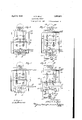
- Fi ure 1 is a plan View of an ordinary non-Fused switch, the switch enclosure having the cover thereof in open position, and the end walls thereof being discontinuous to receive a removable portion.
- a fitting embodying my invention is positioned in the discontinuous portion of said switch box wall;
- Fig. 2 is an end elevational view of the box and fitting shown in Fig. 1; Y
- Fig. 3 is an elevational sectional view taken on the line 3-3 of Fig. 1;
- Figs. 4, 5, 6, 7 and 8 are plan diagrammatic views illustrating the various methods of utilizing the auxiliary fitting to convert an ordinary switch into desirable forms.
- a switch is enclosed in a box 10, the latter being provided with a cover 11, which in Fig. 1 is shown as in open position.
- End walls 12 are discontinuous and in one end wall a fitting is inserted in the opening, it being assumed that the upper edge of said fitting, when in operative position, is flush with the upper edge of the body portion of the box.
- a switch base 13 has mounted thereupon stationary contacts 14 and 15, the latter being provided'with post portions 16 to which are pivoted movable switch blades 17.
- A. link 20 serves to connect the crosshead with an operating member 21, the latter being of the one-piece variety and havin its outer end 22 formed as a handle.
- heauxiliary fitting comprises a plate 23 from which side tangs 24:24: and bottom tangs 25 are struck, As best shown in Fig. 1, this plate may be set in, and close the open end of the wall 12, the tangs 24.- and 25 serving to accurately hold the end plate in position.
- the conducting member 31 is provided with a meter testing clip 34 and an ordinary binding post 35, while the connector 33 likewise comprises a meter test clip36 and a binding post 37.
- An insulating disc38 is interposed between the head 30a of the screw 30 and the base of the shell contact 28.
- Barriers 39 -39 and 39a extend outwardly from theback of insulating block 26, and between the various binding osts and connector elements fastened to t e back of said block, thereby constituting arc preventing members.
- Figs. 1, 2 and 3 I have shown Edison fuses 40 and 41 positioned in the receptacles. In the diagrammatic showings of the Fi s. 5 and 7, these fuses are also positioned in 51c fitting. In these latter figures moreover the manner of wiring the switch when the fitting is utilized to convert a non-fused switch into a fused switch'is clearly shown.
- a novel form of hood which, although it permits a view the state of the fuses, so covers these fuses that they cannot be withdrawn from the receptacles without the lid of the box first being raised.
- a hood is shown at 42 and comprises a body portion and an integrally formed upwardly extending wing 43.
- Fig. 4 I have shown diagrammatically the manner in which my improved fitting may be positioned in a normally fused switch. Under the circumstances, the fitting is applied to the switch in order to provide receptacles thereon into which plugs or lamps may be screwed. It will be noted that the wiring is of course slightly different in this figure since the translating device must be placed in parallel with the line circuits rather than in series therein, as is the case when fuses are inserted in the receptacles.
- This figure illustrates another use to which my fitting may be applied in order to convert a switch of one type into another of a different character. It frequently happens that it is desired to provide a receptacle in the vicinity of a switch to receive a lamp or translating device. By utilizing my fitting such provision ismade without the necessity of any wiring exterior to the switch and without the need of installing the. receptacles in question in the vicinity of the switch. 7
- Figs. 5 and 6, and Figs. 7 and 8 I have illustrated'the manner in which my fitting is utilized in order to convert an ordinary enclosed switch into aswitch having meter testing appurtenances.
- the fitting is utilized to provide testing circuits of the correct character when it is desired to test the meter with the switch blades closed.
- the testing circuits shown in Fig. 8 are of the correct character for use when the switch blades are open, as shown.
- the standard meter is placed in the circuit as shown in Fig. 6, the meter testing clips which are positioned on the back of the auxiliary fitting being utilized. It is of course understood that, during this testing, the box cover is thrown back and the test wires are connected by means of spring clips which are clampcd'on the upturned ends of the test connectors.
- the circuits may be traced as follows: Travelling in the direction of the arrows, the current enters from the line at the right, as indicated, passes through the left hand switch .blade 17, and to the left hand terminal 15.
- the current may fiow through two paths; first, from the terminal 15, through the jumper 44, to the test connector 36, through the upper lead to the load, from the load back t6 the test conncctor 36a, through fuse 41 to test connector 34a, through lead 45, lead 46, to the right hand terminal 15,- through the right hand switch blade 17 right hand terminal 14, and back to the line.
- the circuit just traced will jump the house meter 'and connect the load directly to the line through the switch'and the .fuse 41.
- the other path of the incoming line current may betraced as follows: Through left hand terminal 14, left hand switch blade 17, left hand terminal 15, through lead 47 to a series coil 48 of a house meter 49, the potential coil of said house meter 49 being designated as 50. The current then goes through the lead 51 to test connector 34, through the lead 52, test 'load or resistance 53, and the.
- the circuits in this figure may be traced as follows: Through'the line wire 57 through the fuse 40 to test connector 34. From this point two paths are open; first, through the umper 58 to the left hand terminal 15 and out through lead 59 to the load. Thence the circuit is from the load back through the lead 60 to the right hand terminal 15, through the jumper 61 to the right ,hand terminal 14, through lead 62 to the meter 49, lead 63, to test conngctor 34a, through the fuse 41 to contact 360:, and out to the .line. Thecircuit just traced jumps the house ineter and connects the load directly to the me. e
- the second path of the current is through lead 64, the series coil 48 of the meter, lead 65, to the left hand terminal 14, thence through lead 66, the test load or resistance 67, and the series coil 54 of the standard meter 55, thence through lead 68 to the connector 34a,
- a fitting adapted to close the open end of a standard switch box whereby the switch is convertible for a variety of uses said fitting comprising a removable end wall to close the open end of said box, an insulating block, exteriorly accessible receptacles positioned on said block, and wire connectors and testing clip connectors situated on the interior face of said block,'- said connectors being adapted for interconnection by the insertion of conducting devices in said receptacles.
- a fitting adapted to close the open end of a standard switch box having a cover whereby the switch is convertible for a variety of uses said fitting comprising a removable end wall to close the open end of said box, an insulating block, exteriorly accessible receptacles positioned on said block, wireconnectors and testing clip connectors situated on the interior face of said block, said connectors being adapted for interconnection by the insertion of conducting devices in said receptacles, and a covering hood adapted to be placed over said fuses and to be held in such position by the closing of said box cover.
- a fitting adapted to close the open end of a standard switch box whereby the switch' is convertible for a variety of uses said fitting comprising a removable end wall to close the open end of said box, an insulating block, exteriorly accessible receptacles positioned on said block, and connector members situated on the interior face of said block, each member being provided with a binding post and with a meter-test clip connector whereby either wires from said switch or meter testing clips or both may be connected I to said fitting.
- a quickly removable fitting for an ordinary switch box embodying means for adapting the switch for meter testing said fitting being provided with electrical connectors which may be utilized to test meters with the switch blades either open or closed.
- a fitting for a switch box having a cover comprising a removable end wall member having a fuse block extending therethrough
Landscapes
- Engineering & Computer Science (AREA)
- Power Engineering (AREA)
- Switch Cases, Indication, And Locking (AREA)
Description
April 5, 1932. A. P. BALL ELECTRICAL SWITCH 2 Sheets-Sheet 1 Filed April 28, 1922 Patented Apr. 5, 1 932 ALBERT P. BALL, OF DETROIT, MICHIGAN, ASSIGNOB, TO SQUARE D COMPANY, OF
DETROIT, MICHIGAN, A. CORPORATION OF MICHIGAN ELECTRICAL SWITCH Application filed. April 28,
My invention relates to electrical switches, and it has particular relation to the provision of an auxiliary fitting which may be associated with certain, switches, particularly those switches of theenclosed type whereby the latter are converted into a variety of desirable forms.
More particularly my invention contemplates the provision of a fitting which may be applied to the opening inthe ends of a switch box; that is, my novel auxiliary fitting is interchangeable with the standard removable end wall portions, which are particularly described and claimed in a copending application of Bryson D. Horton, Serial Number 285,269, filed March 26, 1919.
The fitting above referred to comprises an insulating block which is associated with any end plate, the latter being attached to fit in an opening at the end of a switch box.
Mounted on the insulating block are one or more receptacles, said receptacles opening outwardly when the fitting is in operative position and having connecting members extending through the insulating block so'that connections may be made to said receptacles on the rear or inner side of the fitting. Furthermore, I provide meter testing terminals on the inner face (if the fitting, and associate these terminals with the receptacles and with the binding posts on the rear face of the fitting.
It should be further understood that, when my fitting is in operative position, the cover or lid of the switch box may be closed in the normal manner. Upon the closure of said cover the fitting is automatically locked into place by the closed cover, and it is, there-. fore, impossible to obtain access. to the rear face of the fitting and thereby tamper with the connections. 2
The particular advantage of the auxiliary fitting to which I have above referred may be realized and the desirability thereof emphasized, when it is pointed out that this one fitting may be utilized in a variety of different ways. I will hereinafter point out a number of different ways in which this fitting is utilized to convert an ordinary enclosed switch into. a variety of diiferent'de- 1922. Serial N0. 557,079.
sirable forms, but it will be understood that there are other combinations of which these 7Ziirious forms that I point out are suscepti- If it is desired fuse plugs may be inserted in the receptacles, whereby any translating device may be fed from the switch; or lamps may be screwed into the receptacles whereby the ordinary switch box may be converted into a combined switch and fixture, if such use is desirable.
On the other hand the fitting may be utilized to convert an ordinary non-fused switch into a fused switch; under such circumstances the auxiliary fitting constitutes a two-pole cutout, fuses being placed in the receptacles. Under these circumstances the switch may be sealed closed by the utility supplying currentand the distributing circuits thereafter be equipped with fuses accessible to the customer.
Finally, the fitting may be utilized to con- I vert an ordinary switch into a metertesting switch, and it is this use of the fitting that I particularly'desire to emphasize.
The reason forthis emphasis is, that an ordinary enclosed switch which is provided with a removable end plate may be quickly and simply converted into a meter testing switch, by substituting the auxiliary fitting for whatever fitting may be in place in the open end of the switch box. Those skilled in the art will appreciate fully the advantages which accrue by reason of the employment of my novel fitting in this connection.
Moreover, my fitting is extremely flexible in that it permits of meter testing with the main switch either open or closed. The manner in which the fitting may be utilized to eventuate a meter testing device of either character will be better understood from the Y hereinafter description.
is adapted ter are positioned in the auxiliary fitting.
are rendered inaccessible by the closure of the cover of the box and the consequent lock-' ing of said hood into position over the fuses. Incidentally the condition of the fuses, that is, whether or not they are blown, may be noted because of the provision of properl disposed apertures int e fuse covering 1100 For a better understanding of my invention reference may be had to the accompanying drawings, in which:
Fig. 2 is an end elevational view of the box and fitting shown in Fig. 1; Y
Fig. 3 is an elevational sectional view taken on the line 3-3 of Fig. 1; and
Figs. 4, 5, 6, 7 and 8 are plan diagrammatic views illustrating the various methods of utilizing the auxiliary fitting to convert an ordinary switch into desirable forms.
Referring now more particularly to the drawings A switch is enclosed in a box 10, the latter being provided with a cover 11, which in Fig. 1 is shown as in open position. End walls 12 are discontinuous and in one end wall a fitting is inserted in the opening, it being assumed that the upper edge of said fitting, when in operative position, is flush with the upper edge of the body portion of the box.
. A switch base 13 has mounted thereupon stationary contacts 14 and 15, the latter being provided'with post portions 16 to which are pivoted movable switch blades 17.
Extending over themovable blades is a crosshead 18 which is attached thereto by straps 19. A. link 20 serves to connect the crosshead with an operating member 21, the latter being of the one-piece variety and havin its outer end 22 formed as a handle.
heauxiliary fitting comprises a plate 23 from which side tangs 24:24: and bottom tangs 25 are struck, As best shown in Fig. 1, this plate may be set in, and close the open end of the wall 12, the tangs 24.- and 25 serving to accurately hold the end plate in position.
It will be noted that, when the cover 11 is closed down, the plate 23 is permanently held in position and cannot be withdrawn from the end of the box. An insulating block 26 extends through the plate 23 and is secured thereto by screws 27 Two outwardly facing receptacles are positioned in the insulating block 26. These receptacles comprise a shell contact 28 and a center contact 29, the latter being secured to the block by a screw 30 which passes through the block and serves to fasten a conducting connector member 31 to the back of said block. The shell'contact is fastened to the block by a screw 32, which also passes through said block and serves to secure the connector member 33 to the back thereof.
The conducting member 31 is provided with a meter testing clip 34 and an ordinary binding post 35, while the connector 33 likewise comprises a meter test clip36 and a binding post 37. An insulating disc38 is interposed between the head 30a of the screw 30 and the base of the shell contact 28.
Barriers 39 -39 and 39a extend outwardly from theback of insulating block 26, and between the various binding osts and connector elements fastened to t e back of said block, thereby constituting arc preventing members.
In Figs. 1, 2 and 3 I have shown Edison fuses 40 and 41 positioned in the receptacles. In the diagrammatic showings of the Fi s. 5 and 7, these fuses are also positioned in 51c fitting. In these latter figures moreover the manner of wiring the switch when the fitting is utilized to convert a non-fused switch into a fused switch'is clearly shown.
One of the advantageous uses, therefore, to
which my improved fitting may be applied is to effect the conversion of an ordinary switch into one of the fused type. To effect the change it is only necessary to withdraw the ordinary plate which is positioned in the open end of the box and thereafter place in its stead the fitting just describedthe wiring, of course, being altered to cause the circuits to pass through the fuses. If it is desired that the fuses, although in plain view, should be inaccessible to all but properly authorized persons, use may be made of a novel form of hood which, although it permits a view the state of the fuses, so covers these fuses that they cannot be withdrawn from the receptacles without the lid of the box first being raised. Such a hood is shown at 42 and comprises a body portion and an integrally formed upwardly extending wing 43. This latter wing fits flush against the outer and upper portion of the end plate 23- and is secured between the latter and the flange 11a of the box lid, when the latter is closed. Therefore the closure of the box cover serves to hold the hood 42 tightly in place over the fuses rendering the switch, although it is so fused as to leave the fuses in plan view, entirely safe to unauthorized persons.
In Fig. 4 I have shown diagrammatically the manner in which my improved fitting may be positioned in a normally fused switch. Under the circumstances, the fitting is applied to the switch in order to provide receptacles thereon into which plugs or lamps may be screwed. It will be noted that the wiring is of course slightly different in this figure since the translating device must be placed in parallel with the line circuits rather than in series therein, as is the case when fuses are inserted in the receptacles.
This figure illustrates another use to which my fitting may be applied in order to convert a switch of one type into another of a different character. It frequently happens that it is desired to provide a receptacle in the vicinity of a switch to receive a lamp or translating device. By utilizing my fitting such provision ismade without the necessity of any wiring exterior to the switch and without the need of installing the. receptacles in question in the vicinity of the switch. 7
In Figs. 5 and 6, and Figs. 7 and 8 I have illustrated'the manner in which my fitting is utilized in order to convert an ordinary enclosed switch into aswitch having meter testing appurtenances. In the first two of these figures, namely, 5 and 6, the fitting is utilized to provide testing circuits of the correct character when it is desired to test the meter with the switch blades closed. On the other hand the testing circuits shown in Fig. 8 are of the correct character for use when the switch blades are open, as shown.
Having a fused switch with the circuits arranged as shown in Fig. 5; and desiring to test said meter with theswitch blades 17 closed, the standard meter is placed in the circuit as shown in Fig. 6, the meter testing clips which are positioned on the back of the auxiliary fitting being utilized. It is of course understood that, during this testing, the box cover is thrown back and the test wires are connected by means of spring clips which are clampcd'on the upturned ends of the test connectors. shown in Fig. 6, the circuits may be traced as follows: Travelling in the direction of the arrows, the current enters from the line at the right, as indicated, passes through the left hand switch .blade 17, and to the left hand terminal 15. From this point the current may fiow through two paths; first, from the terminal 15, through the jumper 44, to the test connector 36, through the upper lead to the load, from the load back t6 the test conncctor 36a, through fuse 41 to test connector 34a, through lead 45, lead 46, to the right hand terminal 15,- through the right hand switch blade 17 right hand terminal 14, and back to the line. The circuit just traced will jump the house meter 'and connect the load directly to the line through the switch'and the .fuse 41.
The other path of the incoming line current may betraced as follows: Through left hand terminal 14, left hand switch blade 17, left hand terminal 15, through lead 47 to a series coil 48 of a house meter 49, the potential coil of said house meter 49 being designated as 50. The current then goes through the lead 51 to test connector 34, through the lead 52, test 'load or resistance 53, and the.
potential coil of this latter meter being des- I ignated as 540.. It will'be noted that the fuse '40 is withdrawn from its associated receptacle in this figure.
\Vith the wiring arranged as series coil 54, it goes throu in lead to the test connector 34a, then t ough leads 45 and 4.6, right hand terminal 15,- right hand switch blade 17 ri ht hand terminal 14, and
e last traced circuit puts I the series coil of the two meters and thgatest load 53 in series and thereby forms the actual back to the line.
meter testing circuit.- It will be noted that, in the test circuits just described, the switch blades 17 are kept closed.
The circuits in this figure may be traced as follows: Through'the line wire 57 through the fuse 40 to test connector 34. From this point two paths are open; first, through the umper 58 to the left hand terminal 15 and out through lead 59 to the load. Thence the circuit is from the load back through the lead 60 to the right hand terminal 15, through the jumper 61 to the right ,hand terminal 14, through lead 62 to the meter 49, lead 63, to test conngctor 34a, through the fuse 41 to contact 360:, and out to the .line. Thecircuit just traced jumps the house ineter and connects the load directly to the me. e
Beginning again atthe connector 34'the second path of the current is through lead 64, the series coil 48 of the meter, lead 65, to the left hand terminal 14, thence through lead 66, the test load or resistance 67, and the series coil 54 of the standard meter 55, thence through lead 68 to the connector 34a,
through the fuse 41, to the connector 36a,"
and back to the line. This latter circuit puts .the series coils of the two meters and the test load 67 in series and constitutes the an auxiliary fitting constructed in accorch ance with my invention is of marked advantage in the electrical switch art. By its use the ordinary enclosed switch may be converted to a variety of uses, all of which are I highly desirable. It-may be, of course, that other combinations of'the various uses than those which I have above described'ma be desirable under some circumstances. not intend, therefore, to liniit the use of my fitting to only those situations which I have described. ,Because of the construction of this fitting it is extremely flexible in use and may be employed to convert switches in many ways.
ments of my invention as used with switches, it is obvious that many'modifications therein may occur to those skilled in the art without departing from the spirit of this inven While I have described but a few embodi tion, and I desire therefore that the latter be limited only by the showing of the prior art and by the scope of the appended claims.
What I now claim as new and desire to secure by Letters Patent from the United States is:
1. A quickly removable fitting for an ordinary switch box embodying means for adaptin the switch for meter testing,- said fitting being interchangeable with other standard end wall members of a discontinuous-walled switch box.
2. A fitting adapted to close the open end of a standard switch box whereby the switch is convertible for a variety of uses, said fitting comprising a removable end wall to close the open end of said box, an insulating block, exteriorly accessible receptacles positioned on said block, and wire connectors and testing clip connectors situated on the interior face of said block,'- said connectors being adapted for interconnection by the insertion of conducting devices in said receptacles.
3. A fitting adapted to close the open end of a standard switch box having a cover whereby the switch is convertible for a variety of uses, said fitting comprising a removable end wall to close the open end of said box, an insulating block, exteriorly accessible receptacles positioned on said block, wireconnectors and testing clip connectors situated on the interior face of said block, said connectors being adapted for interconnection by the insertion of conducting devices in said receptacles, and a covering hood adapted to be placed over said fuses and to be held in such position by the closing of said box cover. i
4. A fitting adapted to close the open end of a standard switch box whereby the switch' is convertible for a variety of uses, said fitting comprising a removable end wall to close the open end of said box, an insulating block, exteriorly accessible receptacles positioned on said block, and connector members situated on the interior face of said block, each member being provided with a binding post and with a meter-test clip connector whereby either wires from said switch or meter testing clips or both may be connected I to said fitting.
5. A quickly removable fitting for an ordinary switch box embodying means for adapting the switch for meter testing, said fitting being provided with electrical connectors which may be utilized to test meters with the switch blades either open or closed.
6. A fitting for a switch box having a cover comprising a removable end wall member having a fuse block extending therethrough,
' receptacles on said block,'connections from said receptacles to the other side of said block whereby the current passing through said switch may be derived from said receptacles, and means for covering said recepscribed my name.
ALBERT BALL.
Priority Applications (1)
| Application Number | Priority Date | Filing Date | Title |
|---|---|---|---|
| US557079A US1852871A (en) | 1922-04-28 | 1922-04-28 | Electrical switch |
Applications Claiming Priority (1)
| Application Number | Priority Date | Filing Date | Title |
|---|---|---|---|
| US557079A US1852871A (en) | 1922-04-28 | 1922-04-28 | Electrical switch |
Publications (1)
| Publication Number | Publication Date |
|---|---|
| US1852871A true US1852871A (en) | 1932-04-05 |
Family
ID=24223974
Family Applications (1)
| Application Number | Title | Priority Date | Filing Date |
|---|---|---|---|
| US557079A Expired - Lifetime US1852871A (en) | 1922-04-28 | 1922-04-28 | Electrical switch |
Country Status (1)
| Country | Link |
|---|---|
| US (1) | US1852871A (en) |
-
1922
- 1922-04-28 US US557079A patent/US1852871A/en not_active Expired - Lifetime
Similar Documents
| Publication | Publication Date | Title |
|---|---|---|
| US2606232A (en) | Combined meter socket and circuit interrupting device | |
| US4786885A (en) | Molded case circuit breaker shunt trip unit | |
| IE57241B1 (en) | Fittings for motor vehicles | |
| US20180059185A1 (en) | Monitoring unit for monitoring an electrical circuit breaker and circuit breaker comprising such a monitoring unit | |
| US1880543A (en) | Safety fuse block | |
| US1852871A (en) | Electrical switch | |
| USRE21148E (en) | Meter base | |
| US1686289A (en) | Switch | |
| GB2161333A (en) | Electronics box for motor vehicles | |
| US2565314A (en) | Rotatable dihedral protective enclosure for high-voltage apparatus | |
| US2002623A (en) | Electrical switch | |
| US3614537A (en) | Integral-breaker trailer socket with bimetallic breaker blades | |
| US1305998A (en) | fromager and j | |
| US1351043A (en) | Electric switch and fuse box | |
| US1992719A (en) | System of circuit controlling devices | |
| US1729877A (en) | Fuse-panel box | |
| US796821A (en) | Switchboard for meter tests. | |
| US1910660A (en) | Multiple switch | |
| US1338180A (en) | Service and meter-test system and associated apparatus | |
| US1767259A (en) | Protected electric-meter-service appurtenance | |
| US2120574A (en) | Electric meter connection appliance | |
| US1906080A (en) | Switch and fuse mounting | |
| US1767260A (en) | Protected electric-meter-service appurtenance | |
| US1323047A (en) | Electkic-bahge switch | |
| US3275762A (en) | Automatic circuit closer with spring biased normally closed contact structure |