US1852850A - loewe - Google Patents
loewe Download PDFInfo
- Publication number
- US1852850A US1852850A US1852850DA US1852850A US 1852850 A US1852850 A US 1852850A US 1852850D A US1852850D A US 1852850DA US 1852850 A US1852850 A US 1852850A
- Authority
- US
- United States
- Prior art keywords
- hot wire
- valve
- wire
- current
- hot
- Prior art date
- Legal status (The legal status is an assumption and is not a legal conclusion. Google has not performed a legal analysis and makes no representation as to the accuracy of the status listed.)
- Expired - Lifetime
Links
- 241000282320 Panthera leo Species 0.000 title description 3
- 238000010438 heat treatment Methods 0.000 description 13
- 230000035945 sensitivity Effects 0.000 description 7
- 230000003321 amplification Effects 0.000 description 6
- 238000003199 nucleic acid amplification method Methods 0.000 description 6
- 239000011248 coating agent Substances 0.000 description 4
- 238000000576 coating method Methods 0.000 description 4
- 238000010276 construction Methods 0.000 description 4
- 239000011521 glass Substances 0.000 description 3
- 230000005855 radiation Effects 0.000 description 3
- 230000009466 transformation Effects 0.000 description 3
- 235000009854 Cucurbita moschata Nutrition 0.000 description 2
- 240000001980 Cucurbita pepo Species 0.000 description 2
- 235000009852 Cucurbita pepo Nutrition 0.000 description 2
- 230000005540 biological transmission Effects 0.000 description 2
- 238000010586 diagram Methods 0.000 description 2
- 235000020354 squash Nutrition 0.000 description 2
- BSYNRYMUTXBXSQ-UHFFFAOYSA-N Aspirin Chemical compound CC(=O)OC1=CC=CC=C1C(O)=O BSYNRYMUTXBXSQ-UHFFFAOYSA-N 0.000 description 1
- 239000004020 conductor Substances 0.000 description 1
- 238000001816 cooling Methods 0.000 description 1
- 230000001419 dependent effect Effects 0.000 description 1
- 230000000694 effects Effects 0.000 description 1
- 238000004070 electrodeposition Methods 0.000 description 1
- 230000005484 gravity Effects 0.000 description 1
- 238000000034 method Methods 0.000 description 1
- NJPPVKZQTLUDBO-UHFFFAOYSA-N novaluron Chemical compound C1=C(Cl)C(OC(F)(F)C(OC(F)(F)F)F)=CC=C1NC(=O)NC(=O)C1=C(F)C=CC=C1F NJPPVKZQTLUDBO-UHFFFAOYSA-N 0.000 description 1
- 238000012216 screening Methods 0.000 description 1
- 230000003068 static effect Effects 0.000 description 1
- 230000001629 suppression Effects 0.000 description 1
Images

Classifications
-
- G—PHYSICS
- G01—MEASURING; TESTING
- G01R—MEASURING ELECTRIC VARIABLES; MEASURING MAGNETIC VARIABLES
- G01R21/00—Arrangements for measuring electric power or power factor
-
- G—PHYSICS
- G01—MEASURING; TESTING
- G01R—MEASURING ELECTRIC VARIABLES; MEASURING MAGNETIC VARIABLES
- G01R21/00—Arrangements for measuring electric power or power factor
- G01R21/02—Arrangements for measuring electric power or power factor by thermal methods, e.g. calorimetric
Definitions
- y invention consists of the combination of an electron valve with a hot wire which in known manner 'elongates or increases its deflection according to the assing current to be measured. It may best e applied by the position of one or several electrodes of an electron valve being in relation to the other electrodes of the same amplifier system chan ed under the influence of the change in the s a e of a hot wire or similar conductor by the entry of current. According change will appropriately be eflected in such a manner that the change in the position of l the electrode due to the heating of the hot wire produces a variation of the plate current of an electron valve which for this purpose is operated with constant'plate voltage source and grid bias.
- the control of the electrode position by the hot wire may be eflected by the walls of the electrode valves being in some spots madeso e currents passing manner that it is electrically independent thin that a deflection is possible.
- the change of position of the hot-wire outside the valve thus influences across the deflection of the glass bulb wall the position of an electrode which is comparatively well connected with this spot of the wall of the bulb, whilst the other electrodesare best connected with the other points of the bulb-wall (or the valve pedestal) and are therefore not exposed to p the relative changes of position.
- the hot-wire is sealed into an electron valve and influences directly the position of an electrode inside such a valve.
- the electrode may be influenced in such a way that the position of the anode is changed whilst at the same time the position of grid and cathode to one another remains constant. In this manner, as a rule, particularly good v results mag be obtained.
- the V grid may e changed in its position to the anode and incandescent'filament or in the density of its mesh and the like. By moving the grid with respect to the incandescent wire specially sensitive embodiments of the invention may be obtained.
- the hot wire may be connected in such a from the connection of the electron valve or so that one of the hot-wire leads coincides with one of the electron leads, e. g. with the grid lead, or that the two leads of the hot- Wlle coincide each with one lead of an elec- 5 trode, e. g. with the two cathode-leads.
- This may be efiected in such a manner that by the heating of the hot-wire only the position of the cathode in relation to the other electrodes is changed, for instance if cathodes are used the emission of which is independent or little dependent upon the temperature of the oathode, e.
- the wire to be heated may be arranged in a multiple valve which simultaneously contains in known manner a resistance amplifying cascade (e. a triple valve).
- a resistance amplifying cascade e. a triple valve.
- the further one or two eads necessary for this purpose do not cause any additional difiiculty in the construction of the multiple valve.
- the valve is best constructed in such a manner that the fluctuations of the plate current in the plate circuits, especially in the plate circuit of the terminal stage under the influence of the heating are as large as possible, while the feed current has not to be large.
- the grid bias could be adjusted in such a way that the smallest plate currents to be expected are almost zero. If the measurin or indicating instrument to be connecte at the end, is not loaded with considerable feed currents, a higher sensitivity may be obtained in the case of many arrangements (for instance if less sensitive hot wire instruments are used in the output circuit). With such indicating instruments, however, like olarized relays in the output circuit, which require a rectified current of fixed minimum current intensity and operate on the fluctuations of such a current, the grid bias is adjusted so as to produce such 9. current in every instance.
- the sensitivity of hot wire instruments may be increased by the increase of the amplitude of movement of the hot wire by means of a (mechanical) lever transformation and by the subsequent transmission of such amplitude to an indicator.
- the sensitivity is increased to completely difl'erent orders of magnitude if such a mechanical transformation for the increase of the amplitude of movement is first connected to a hot wire and if subsequently the position of the electrode of an amplifier system is controlled with the amplitudes thus increased, if thereb a further considerable increase of sensitivity is obtained and if finally by connection with a normal amplifier cascade the current, thus changed, of the primary valve is regenerated.
- the hot wire is considerably heated it is advisable in this connection to arrange the hot wire close to an uncoated point of the glass wall in order that the factors of emission for the hot wire remain constant. If, however, the temperatures of the hot wire to be expected, are so small that the heat discharged by the hot wire does not noticeably influence the temperature of the valve, it will be advisable to arrange the hot wire opposite those points of the valve where by the coating of the walls it is protected from outside disturbances. In this case it may be particularly advisable to arrange the incandescent filament, if any, of the valve close to an uncoated point in order that the heat emitted by it may be rapidly and directly radiated.
- the coated part of the glass bulb such a shape as to effect that the part of the heat evolved by the incandescent filament which is radiated against the coated portions of the inner wall of the valve, after being once reflected by the valve parts is directly thrown to the outside.
- This may be done by the incandescent wire being arranged in the focus of a parabolically sha ed coated head of the electron valve so t at the heating of the incandescent filament is prevented from influencing the heating of the hot wire.
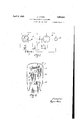
- Fig. 1 is a diagram of a circuit in which the valve which, according to my invention, is controlled by a hot wire may be used in a connection which results in a very great sensitivity.
- Fig. 2 shows a valve in which the hot wire is arranged inside the same valve which contains the electrode system to be controlled and in which the control of one electrode (the grid) is effected by a lever transmission.
- Fig. 3 is an arrangement in which one cathode which, in both the cold and hot state, emits electrons, changes its position.
- Fig. 4 shows an appropriate arrangement of the valve coating through whichrthe heat generated by the incandescent filament is thus reflected to the outside of the valve, so that the hot wire is not influenced in a disturbing manner.
- Fig. 1, 1 is a discharge'vessel any one electrode of which is controlled in its position by the hot wire H being arranged in the interior of the discharge vessel.
- the figure indicates by a dash-dot line 2 diagrammatically that the incandescent filament 3 is by the hot wire changed in its position in relaelectron valve 1 whose cathode tion to the other electrodes, but the circuit diagram of Fig. 1 is in other manner useful for a different control of electrodes.
- the 3 may, for instance, be heated by means of a static current source, e. g.-by means of the accumulator 4, the grid 5 and anode 6 in relation to the cathode 3 may also lie at a constant and not fluctuating potential, for instance a plate battery 7.
- a further electron valve '11 is joined u in whose plate circuit or in the plate circuit of a following stage coupled in a similar manner any amm-eter 12 may be arranged which need not be particularly sensitive.
- the hot wire H may be a thin wire compared with the lead in wires 13 and 14 to which the electric factor (voltage and the like) may be joined at M. In this arrangement the hot wire H is protected against unevenly cooling influences by suitable ing devices, a screen and the like.
- Fig. 2 shows in a valve 1 a cylindrical electrode system consisting of the stretched incandescent wire 3, the spirally wound grid 5 and the cylindrical anode 6.
- a valve 1 a cylindrical electrode system consisting of the stretched incandescent wire 3, the spirally wound grid 5 and the cylindrical anode 6.
- Fig. 3 shows diagrammatically an electron valve with flat plate 6, with zig-zag strained grid 5 and V-shape strained cathode 3 which rection vertical to the l (indicated by a considerable variation of the plate current 'erated in it.
- the right end changes its position corresponding to the heat expansion of the thread 3 by a spring 23, for example, stretching and straining the "cathode 3 towards the right whilst at the same end a'spring 24 grips in the dilevel of the drawings and upon a change of position of the thread as a consequence of a heating draws the thread outside.
- the level of the drawings i. e. away from the grid (or possibly nearer to the grid).
- Fig. 3 may also beefiected such that the cathode 3 is arranged as a normal incandescent filament and that corresponding fluctuations of the emission current varied by the changing temperatures of the hot wire are measured at the plate current or for further amplification are led to an amplification cascade. In this arrangement it may be expedient in the interest of sensitivity, though not being always necessary, to provide a separate grid 5.
- Fig. 4 shows diagrammatically a valve 1 the upper part of which has a mirror coating a double line).
- the mirrorcoated head is constructed as a rotation paraboloid or a parabolic cylinder or the like in the focus of which the incandescent filament 3 of the electrode system and the anode 6 and grid 5 are arranged so that the heat evolved by the electrode system and especially-by the incandescent filament 3 is emitted outside the valve (cf. the dotted primary rays 26 and the reflected rays 27).
- he mirror coated portion' may' be given any other shape where a dispersal of the heat generated inside the valve is effected to the outside in'order that the hot wire H may not be noticeably influenced by the radiation.
- the hot wire H warped to the direction of the elec rode system axis and particularly to the direction of the incandescent filament 3.
- the hot wire may come to lie in the shadow of the plate cylinder 6, so that it neither reflects heat radiation nor obtains reflected heat radiation from the incandescent filament 3. If, as indicated in Fig. 4, it is outside arranged in the neighbourhood of the uncoated portion of the bulb 1, it rapidly emits directly the heat gen- The apparatus then has little heat inertia. Therefore only a short starting time is necessary before the instruments indicate well and evenly.
- My invention is not limited to those measuring instruments by means of which electric values are to be measured directly; it may with the appropriate changes be applied also in those cases in which other factors influence a hot wire and indicate its changes, e. g. in the operation of a hot Wire in fire alarms and similar indicating devices.
- a measuring instrument with a hot wire and a system with several electrodes and means to influence the relative position of the electrodes by the hot wire.
- a measuring instrument with a hot wire and a system with several electrodes and means to influence the position of the cathode with respect to the other electrodes by the hot wire.
- a hot wire measuring instrument a hot wire and an electrode system and means to influence the amplification factor of the electrode system by heating the hot wire.
- a measuring instrument with a hot wire and a system with several electrodes and means to influence the relative position of the electrodes by the hot wire arranged in a common vacuum bulb.
- a measuring instrument with a hot wire and a system with several electrodes and means to influence the'position of the cathode with respect to the other electrodes by the hot wire the cathode having a photo-electric coat being influenced by a source of constant light intensity.
Landscapes
- Engineering & Computer Science (AREA)
- Power Engineering (AREA)
- Physics & Mathematics (AREA)
- General Physics & Mathematics (AREA)
- Control Of Resistance Heating (AREA)
Description
S. LOEWE April 5, 1932.
HOT WIRE MEASURING INSTRUMENT Filed Jan. 20, 1930 2 Sheets-Sheet l v Jaw 7f:
rect current and alternating current of any fre uency.
y invention consists of the combination of an electron valve with a hot wire which in known manner 'elongates or increases its deflection according to the assing current to be measured. It may best e applied by the position of one or several electrodes of an electron valve being in relation to the other electrodes of the same amplifier system chan ed under the influence of the change in the s a e of a hot wire or similar conductor by the entry of current. According change will appropriately be eflected in such a manner that the change in the position of l the electrode due to the heating of the hot wire produces a variation of the plate current of an electron valve which for this purpose is operated with constant'plate voltage source and grid bias.
By this method it is ossible to transform small variations of t through the hot wire into large variations of the plate current. A further increase of the transformation may be eflt'ected by the plate circuit of the first electron valve being in known manner coupled with several further electron valves, e. g. with a resistance amplifymg cascade when minute variations of cur-' rent to be measured correspond toconsiderable variations of current of the plate current of the terminal .valve. These variations may be indicated in several known ways, for instance acoustically,-or may be measured, for instance, by any galvanometer, possibly also by a less sensitive hot-wire instrument. If desired, any relay, too, which has to operate on a smaller current intensity, may be actuated by the terminal plate current circuit. 7
The control of the electrode position by the hot wire may be eflected by the walls of the electrode valves being in some spots madeso e currents passing manner that it is electrically independent thin that a deflection is possible. The change of position of the hot-wire outside the valve thus influences across the deflection of the glass bulb wall the position of an electrode which is comparatively well connected with this spot of the wall of the bulb, whilst the other electrodesare best connected with the other points of the bulb-wall (or the valve pedestal) and are therefore not exposed to p the relative changes of position. According to a further object of my in-. vention the hot-wire is sealed into an electron valve and influences directly the position of an electrode inside such a valve. The electrode may be influenced in such a way that the position of the anode is changed whilst at the same time the position of grid and cathode to one another remains constant. In this manner, as a rule, particularly good v results mag be obtained. In addition the V grid may e changed in its position to the anode and incandescent'filament or in the density of its mesh and the like. By moving the grid with respect to the incandescent wire specially sensitive embodiments of the invention may be obtained.
Finally it is possible to influence the cathode in its position by means of the hot-wire. The hot wire may be connected in such a from the connection of the electron valve or so that one of the hot-wire leads coincides with one of the electron leads, e. g. with the grid lead, or that the two leads of the hot- Wlle coincide each with one lead of an elec- 5 trode, e. g. with the two cathode-leads. This may be efiected in such a manner that by the heating of the hot-wire only the position of the cathode in relation to the other electrodes is changed, for instance if cathodes are used the emission of which is independent or little dependent upon the temperature of the oathode, e. g. in the case of photoelectric emission or in such amanner that at the same time with the heating of the hot-"wire the'emission of the'cathode is increased so that with a constant grid potential the corresponding plate current fluctuates to a considera ole degree In order to increase the sensltivlty it may be useful to combine several of the abovementioned arrangements.
In order to obtain particularly handy and well useful hot-wire galvanometers of high sensitivity, the wire to be heated may be arranged in a multiple valve which simultaneously contains in known manner a resistance amplifying cascade (e. a triple valve). The further one or two eads necessary for this purpose do not cause any additional difiiculty in the construction of the multiple valve. By such an arrangement an apparatus is obtained in a single valve which reacts upon very small current intensities with great changes of the output plate current.
' The valve is best constructed in such a manner that the fluctuations of the plate current in the plate circuits, especially in the plate circuit of the terminal stage under the influence of the heating are as large as possible, while the feed current has not to be large.
, Therefore the grid bias could be adjusted in such a way that the smallest plate currents to be expected are almost zero. If the measurin or indicating instrument to be connecte at the end, is not loaded with considerable feed currents, a higher sensitivity may be obtained in the case of many arrangements (for instance if less sensitive hot wire instruments are used in the output circuit). With such indicating instruments, however, like olarized relays in the output circuit, which require a rectified current of fixed minimum current intensity and operate on the fluctuations of such a current, the grid bias is adjusted so as to produce such 9. current in every instance.
It is known that the sensitivity of hot wire instruments may be increased by the increase of the amplitude of movement of the hot wire by means of a (mechanical) lever transformation and by the subsequent transmission of such amplitude to an indicator. The sensitivity is increased to completely difl'erent orders of magnitude if such a mechanical transformation for the increase of the amplitude of movement is first connected to a hot wire and if subsequently the position of the electrode of an amplifier system is controlled with the amplitudes thus increased, if thereb a further considerable increase of sensitivity is obtained and if finally by connection with a normal amplifier cascade the current, thus changed, of the primary valve is regenerated.
In constructing the apparatus according to my invention provision should be made against undesired heating of the hot wire from other sources. This is effected for instance in the cases in which for any reasons whatsoever the heat supply b the heating would not be constant, by a t ermo-technic screening of the hot wire against the heat of the incandescent filament. It will be best to arrange the hot wire in such points of the valve in which upon the short operation of the valve on the one hand and upon a short heating of the hot wire on the other hand a constant temperature is produced. For such 1purpose those valves are most suitable the ulbs of which are either not at all or only in part provided with a mirror-like coating. If the hot wire is considerably heated it is advisable in this connection to arrange the hot wire close to an uncoated point of the glass wall in order that the factors of emission for the hot wire remain constant. If, however, the temperatures of the hot wire to be expected, are so small that the heat discharged by the hot wire does not noticeably influence the temperature of the valve, it will be advisable to arrange the hot wire opposite those points of the valve where by the coating of the walls it is protected from outside disturbances. In this case it may be particularly advisable to arrange the incandescent filament, if any, of the valve close to an uncoated point in order that the heat emitted by it may be rapidly and directly radiated. It may finally'be expedient to give the coated part of the glass bulb such a shape as to effect that the part of the heat evolved by the incandescent filament which is radiated against the coated portions of the inner wall of the valve, after being once reflected by the valve parts is directly thrown to the outside. This may be done by the incandescent wire being arranged in the focus of a parabolically sha ed coated head of the electron valve so t at the heating of the incandescent filament is prevented from influencing the heating of the hot wire.
The four figures represent exemplary forms of construction of my invention.
Fig. 1 is a diagram of a circuit in which the valve which, according to my invention, is controlled by a hot wire may be used in a connection which results in a very great sensitivity.
Fig. 2 shows a valve in which the hot wire is arranged inside the same valve which contains the electrode system to be controlled and in which the control of one electrode (the grid) is effected by a lever transmission.
Fig. 3 is an arrangement in which one cathode which, in both the cold and hot state, emits electrons, changes its position.
Fig. 4 shows an appropriate arrangement of the valve coating through whichrthe heat generated by the incandescent filament is thus reflected to the outside of the valve, so that the hot wire is not influenced in a disturbing manner.
In Fig. 1, 1 is a discharge'vessel any one electrode of which is controlled in its position by the hot wire H being arranged in the interior of the discharge vessel. The figure indicates by a dash-dot line 2 diagrammatically that the incandescent filament 3 is by the hot wire changed in its position in relaelectron valve 1 whose cathode tion to the other electrodes, but the circuit diagram of Fig. 1 is in other manner useful for a different control of electrodes. In the 3 may, for instance, be heated by means of a static current source, e. g.-by means of the accumulator 4, the grid 5 and anode 6 in relation to the cathode 3 may also lie at a constant and not fluctuating potential, for instance a plate battery 7. By a suitable connection, expediently by a resistance amplification consisting of a plate-resistance 8, block condenser 9 and leak resistance 10, a further electron valve '11 is joined u in whose plate circuit or in the plate circuit of a following stage coupled in a similar manner any amm-eter 12 may be arranged which need not be particularly sensitive. The hot wire H may be a thin wire compared with the lead in wires 13 and 14 to which the electric factor (voltage and the like) may be joined at M. In this arrangement the hot wire H is protected against unevenly cooling influences by suitable ing devices, a screen and the like.
If a current passes .through the wire H and if in consequence of the heatin the latter expands, it influences any one of the electrodes of the first valve 1. With constant grid bias the plate current of such first valve thereupon changes. The variations are amplified by the further amplification stages with the result that the terminal stage shows protectwhich may be measured by a simple instrument.
Fig. 2 shows in a valve 1 a cylindrical electrode system consisting of the stretched incandescent wire 3, the spirally wound grid 5 and the cylindrical anode 6. Through the squash of the valve 1 two leads 13 and 14' presses by its own gravity or, if necessary,
with the aid of the strain of a spiral spring 41 fastened'at the squash upon the lever 19, the right end of which is thereby pressed downward so that its left end holds the hot wire H in tension. The hot wire extends as soon as it is heated by the passage of a current supplied by means of the leads 13 and 14. Consequently the grid is pulled downward. The amplification factor of the valve changes accordingly, so that even with a constant grid bias the plate current is fluctuating. With the arrangement according to Fig. 2 it is furthermore possible to use one of the' leads 13 or 14 simultaneously as a lead for the constant grid bias.
Fig. 3 shows diagrammatically an electron valve with flat plate 6, with zig-zag strained grid 5 and V-shape strained cathode 3 which rection vertical to the l (indicated by a considerable variation of the plate current 'erated in it.
the right end changes its position corresponding to the heat expansion of the thread 3 by a spring 23, for example, stretching and straining the "cathode 3 towards the right whilst at the same end a'spring 24 grips in the dilevel of the drawings and upon a change of position of the thread as a consequence of a heating draws the thread outside. the level of the drawings, i. e. away from the grid (or possibly nearer to the grid).
The construction according to Fig. 3 may also beefiected such that the cathode 3 is arranged as a normal incandescent filament and that corresponding fluctuations of the emission current varied by the changing temperatures of the hot wire are measured at the plate current or for further amplification are led to an amplification cascade. In this arrangement it may be expedient in the interest of sensitivity, though not being always necessary, to provide a separate grid 5. Fig. 4 shows diagrammatically a valve 1 the upper part of which has a mirror coating a double line). The mirrorcoated head is constructed as a rotation paraboloid or a parabolic cylinder or the like in the focus of which the incandescent filament 3 of the electrode system and the anode 6 and grid 5 are arranged so that the heat evolved by the electrode system and especially-by the incandescent filament 3 is emitted outside the valve (cf. the dotted primary rays 26 and the reflected rays 27). he mirror coated portion'may' be given any other shape where a dispersal of the heat generated inside the valve is effected to the outside in'order that the hot wire H may not be noticeably influenced by the radiation. It may be expedient, moreover,'to arrange the level direction of the hot wire H warped to the direction of the elec rode system axis and particularly to the direction of the incandescent filament 3. Or the hot wire may come to lie in the shadow of the plate cylinder 6, so that it neither reflects heat radiation nor obtains reflected heat radiation from the incandescent filament 3. If, as indicated in Fig. 4, it is outside arranged in the neighbourhood of the uncoated portion of the bulb 1, it rapidly emits directly the heat gen- The apparatus then has little heat inertia. Therefore only a short starting time is necessary before the instruments indicate well and evenly.
A considerable heat inertia is preferred in many cases for the suppression of undesired fluctuations in electron valves (e. g.
with thick short incandescent wires for the purpose of direct heating from the mains the fluctuations of which shalt not appear inv the plate current). In contradistinction to this it is expedient for my invention that not only the hot wire, but the eiectrode system too should possess little heat inertia in order that the plate current may follow the fluctuations of the hot wire condition. For this purpose the hot wire in the arrangement according to Fig. 3 as well as in the other forms of construction is appropriately made very thin.
My invention is not limited to those measuring instruments by means of which electric values are to be measured directly; it may with the appropriate changes be applied also in those cases in which other factors influence a hot wire and indicate its changes, e. g. in the operation of a hot Wire in fire alarms and similar indicating devices.
I claim:
1. A measuring instrument with a hot wire and a system with several electrodes and means to influence the relative position of the electrodes by the hot wire.
2. A measuring instrument with a hot wire and a system with several electrodes and means to influence the position of the cathode with respect to the other electrodes by the hot wire.
3. In a hot wire measuring instrument a long thin filament and electrodes neighboured to this filament and springs to avoid variations of the distance of this filament to the further electrodes if the filament is expanded by the heating.
4. In a hot wire measuring instrument a hot wire and an electrode system and means to influence the amplification factor of the electrode system by heating the hot wire.
5. A measuring instrument with a hot wire and a system with several electrodes and means to influence the relative position of the electrodes by the hot wire arranged in a common vacuum bulb.
6. A measuring instrument with a. hot wire and a system with several electrodes and means to influence the relative position of the electrodes by the hot wire together with amplifying systems arranged in a common vacuum bu- 7. A measuring instrument with a hot wire and a system with several electrodes and means to influence the position of the cathode with respect to the other electrodes by the hot wire, the cathode having a coat emitting electrons when the temperature is slightly increased.
8. A measuring instrument with a hot wire and a system with several electrodes and means to influence the'position of the cathode with respect to the other electrodes by the hot wire the cathode having a photo-electric coat being influenced by a source of constant light intensity.
signature.
SIEGMUND LOEWE.
Publications (1)
| Publication Number | Publication Date |
|---|---|
| US1852850A true US1852850A (en) | 1932-04-05 |
Family
ID=3423639
Family Applications (1)
| Application Number | Title | Priority Date | Filing Date |
|---|---|---|---|
| US1852850D Expired - Lifetime US1852850A (en) | loewe |
Country Status (1)
| Country | Link |
|---|---|
| US (1) | US1852850A (en) |
-
0
- US US1852850D patent/US1852850A/en not_active Expired - Lifetime
Similar Documents
| Publication | Publication Date | Title |
|---|---|---|
| US2683223A (en) | X-ray tube | |
| US2569872A (en) | Electron discharge tube | |
| US2306272A (en) | Electro-optical relay | |
| US3002101A (en) | Image amplifier | |
| US1852850A (en) | loewe | |
| US2788452A (en) | Thermal image detecting tube | |
| US2617046A (en) | X-ray apparatus | |
| US2534668A (en) | Automatic inverse feedback method and means for correcting response characteristic of phototube circuits | |
| US2175700A (en) | Electronic indicating device | |
| US2280303A (en) | Electron multiplier system | |
| US2276152A (en) | Thermionic valve voltmeter and potentiometer circuits and the like | |
| US2243034A (en) | Fluorescent indicating device | |
| US2842694A (en) | X-ray apparatus | |
| Langmuir | The pure electron discharge. and its applications in radio telegraphy and telephony | |
| US2979622A (en) | Thermal image converter | |
| US3082340A (en) | Radiation sensitive device | |
| US2230216A (en) | High frequency oscillation generator | |
| US2228895A (en) | Electrical translating device | |
| US2803782A (en) | Triode thermionic tube | |
| US1938426A (en) | Light sensitive apparatus | |
| US1696103A (en) | Electric discharge tube | |
| US2282198A (en) | Photoelectric differential analyzer | |
| US2152321A (en) | Electronic tube and apparatus employing same | |
| US2440537A (en) | Exciter lamp supply | |
| US1883926A (en) | Combination of alpha phototube and an amplifier |