US1852849A - Duplex fastener setting machine - Google Patents
Duplex fastener setting machine Download PDFInfo
- Publication number
- US1852849A US1852849A US218458A US21845827A US1852849A US 1852849 A US1852849 A US 1852849A US 218458 A US218458 A US 218458A US 21845827 A US21845827 A US 21845827A US 1852849 A US1852849 A US 1852849A
- Authority
- US
- United States
- Prior art keywords
- work
- carrier
- punch
- machine
- feed
- Prior art date
- Legal status (The legal status is an assumption and is not a legal conclusion. Google has not performed a legal analysis and makes no representation as to the accuracy of the status listed.)
- Expired - Lifetime
Links
- 230000033001 locomotion Effects 0.000 description 21
- 238000004080 punching Methods 0.000 description 20
- 230000007246 mechanism Effects 0.000 description 11
- 230000000694 effects Effects 0.000 description 7
- 230000009471 action Effects 0.000 description 5
- 230000008859 change Effects 0.000 description 2
- 239000000463 material Substances 0.000 description 2
- 230000004048 modification Effects 0.000 description 2
- 238000012986 modification Methods 0.000 description 2
- 230000000284 resting effect Effects 0.000 description 2
- 125000000349 (Z)-3-carboxyprop-2-enoyl group Chemical group O=C([*])/C([H])=C([H])\C(O[H])=O 0.000 description 1
- 239000000969 carrier Substances 0.000 description 1
- 230000000994 depressogenic effect Effects 0.000 description 1
- 230000005484 gravity Effects 0.000 description 1
- 238000007689 inspection Methods 0.000 description 1
- 230000013011 mating Effects 0.000 description 1
- 238000005192 partition Methods 0.000 description 1
- 229920000136 polysorbate Polymers 0.000 description 1
Images


Classifications
-
- A—HUMAN NECESSITIES
- A43—FOOTWEAR
- A43D—MACHINES, TOOLS, EQUIPMENT OR METHODS FOR MANUFACTURING OR REPAIRING FOOTWEAR
- A43D100/00—Setting or removing eyelets, buttons, lacing-hooks, or elastic gussets in shoes
- A43D100/02—Punching and eyelet-setting machines or tools
Definitions
- This invention relates to fastener setting machines of the duplex type, that is, in which a pair of fasteners are set simultaneously in opposed relation in two layers of work.
- One of the objects of the present invention is to simplify and lighten the machine to make possible high speed with a minimum of vibration.
- a further object is to provide such a mal chine in which the punching and feeding of the work is effected before the fastener setting operation in each cycle, the fasteners being presented and set in the first feed positionin v the cycle.
- Figure 1a is a detail inperspective.
- I t Figure 2 is a right side elevation of the machine.
- Figure is a detail section through: the punching mechanism and work support.
- Figure 7 1s a section on line 7-7ofF1gure 1.
- Figures 8 and 9 are details of the stop cam Figure 10 is a fragmentary front elevation of the machine.
- Figure llis a detail section on-line 1111"
- Figures 12, 13 and 14 aredetails showing the relative positions of raceways, punches and sets during successive stages of the cycle of operation.
- Figure 15 is a sectional detail showing a modification.
- operative mechanisms are carried entirely by a slngle upstanding web 1 havlng a supporting foot 2 at its lower end by which it" may be carried onia suitable bench or platform.
- the upper end portion of the web 1 integral pins 10 to end flanges 11 of a tool supporting block or carrier indicated as a Whole at 12.
- This block is provided with spaced arms leihaving enlarged head por tions15 at. their ends through which are upper and lower sets 19' and 20.
- the arms l l are joined by a web 21.
- the pivots 10 not only connect the links 7 to the arms 14, but they also pivotally connect these members with'upper and lower levers 25, the rearends of which are pivotedby the screws 26 to up I per and lower bearing bosses 27 carried by the web 1 and extending within a transverse opening 28 therethrough.”
- the tool-supporting block has a pivotal motion about the pins 10 which permits it a motion in addition to the feed motion produced by swinging of the levers 25.
- This pivotal motion is for the purpose of bringing the punches and sets alternately into operative relation to the work.
- the arms 14 are extended rearwardly of the pivot 10 and are provided with wear pieces 85 which are normally pressed into engagement with the ends of adjusting wear screws 36 extended through flanges 37 in the sides of the arms 25, the screws 36 being held in adjusted position as by means of the lock nuts 38.
- the feed frame 6 is given its traversing motion by means of a cam positioned on the forward end of a cam shaft 51 which is journaled in bosses 52 and 53 projecting from one side of the web 1, the shaft 51 being arranged in a forwardly and downwardly inclined position.
- the cam 50 is provided with a face cam groove 55 within which rides a follower 56 on a lever 57, this lever being pivoted at 58 to a portion 59 projecting laterally from the web 1, as shown in Figure 11.
- the lever 57 is provided with a longitudinal slot within which rides a block 60 carried by a pin 61 journaled in and projecting inwardly from an adjustment slide 62 (see Figure 10) this slide having an integral portion projecting through a slot 64 in the feed frame.
- the pin 61 is held to the slide 62 by a screw 63 ( Figure 10).
- a screw 63 Figure 10
- the distance of the block 60 from the fulcrum of the lever may be adjusted thus to change the effective throw of this lever to actuate the feed frame.
- Both layers of work in which the fasteners are to be set are placed upon the work support 70, which is fixed to a bracket 71 extending laterally from the supporting web 1, a spring presser foot 7 2 carried by the work support holding the work in place thereon. As shown best in Figures 3 and 4, this work support and press-er foot are each provided with a slot or clearance space 73 within which the punch mechanism may operate during the punching and feeding movements.
- the lower punch 18 is provided at its upper end with a removable anvil 75 fixed by a threaded retaining collar 76 to the shank portion of the punch, which for the punching operation is moved upwardly into the clearance space 73 at the same time that a hollow cutting punch 77 carried by the upper punch ing device descends and cuts through the work against the anvil 75.
- An opening 78 through the cutting punch 77 and opening laterally through the side of its supporting shank portion permits the escape of the punchings.
- the sets are shown as of usual form each being provided with a central spindle which may engage within the eyelet barrel to remove it from the raceway and present it to the hole in the work.
- the sets having been moved toward each other to take the eyelets from the raceway, means are provided for rocking the punch and set carrier, so that the eyelets are presented to the holes punched in the work, whereupon the sets are actuated to set the eyelets therein.
- This movement of the punch and set carrier to present the eyelets to the work is effected by means of a rod 82 slidable through the web member 1. and having at its rear end a cam follower 83 engaging in an edge cam groove 84 in a cam 85 also carried by the shaft 51.
- the outer end of the rod 82 when this rod is pushed outwardly by the action of the cam 85, impinges on the web 21 of the block 12, thus rocking this block about the pivot 10 against: the tens on of the springs 40.
- the outer end of the rod 82 carries an anvil plate 88 adapted to be interposed between the setting devices so that the eyelets are clinched thereagainst.
- the rod 82 is then drawn backward, the levers 25 swung back to starting position, the position of the feed block 62 detern'iining how far back of the final setting posit on this start-ing position is situated. thus determining the spacing between the eyelets.
- the anvil plate instead of carrying the anvil plate by the rod 82, it may be carried by the tool block 12 being so shown in 89 in Figure 15.
- the punches and sets are reciproeated toward and from each other and both l'QliltlX't-Z to the work support to effect the punch ng and setting actions, their motions toward each other being produced by the rocking of a pair of hammers 90 pivoted at. 91 to the web 1 and having connected to the opposite ends of their pivots, arms 92 provided with intermeshing gear segments 93 at their adjacent ends, whereby ntion of one hammer causes opposite simultaneous motion of the other.
- One of the arms 92 herein shown the lower arm, has a rearward extension94 provided with a cam follower 95 which rides in a groove in a cam 96 keyed to the main drive shaft 97 of the machine
- the shaft 51 is driven from this main shaft through a 98 and 99011 these respective shafts,
- Each oft'he hammers 90 has an adjustable head portion 100 which bears on the punches and actuates them fortheir punching stroke
- the layers of work are punched together by punching means common to both while they rest in superposed relation and in contact on the upper face of 1 a work support and that thereafter an individual fastener set in each of the two layers of work in the holes so punchedby a setting 1 device individual for each of the two layers and an anvil'placed between the layers'and' devices cooperate.
- the drive shaft97' is shown as driven by a belt pulley 120 journaled thereon (see Fig-' ure 7) which is provided in a hub portion 121 with a clutch face 122whichcooperates with a mating clutch I face on a clutch collar 123 slidable on the shaft 97 into and out of clutch ing relation with the pulley clutch face.
- This plate is-slidablv guided on bolts 12'? which hold it against rotation, coil-springs 126 surrounding these bolts pressing theplate headsand tending; to hold the collar 128 in clutching engagement-with the pulley
- This clutch collar has'a cam face member shown detached in Figures 8 and 9 at 128 with which cooperates the upper end of a rod 129 vertically slidable througha bracket 130 carried by the webmember 1.
- This depression 138 also performs the function oftending to prevent rebound when therotation of the, clutch collar is final-i ly positively stopped byimpiiigement of thev shoulder 142 onithe cam member 128 against the rod129.
- a lock ing rod 144 is provided whichmay be prov jected' upwardly by any suitable means, asby a rocking handlever 145, in frontof a flange,
- a pin 147 is eccentrically disposed to the pivotal axis 148 of the lever'145, and engages between spaced pins1149 carried by'the rod 144.
- the rod144 may be held in the desired position by engagement of a spring pressed locking dog 150carried by the lever 145 in either of a pair of'notches as 151 in the edge of a fixed disk 152.
- the rodi129, as shown in Figure 1 may have a hooked rod 156 attached thereto by which'it maybe depressed, if desired, as by means of a foot treadle (not shown).
- the upper raceway Above its lower end the upper raceway is given a half twist as shown in Figures 1 and 3, so as to reverse the position of the eyelets therein as they are taken from the hopper, the upper raceway presenting the eyelets to its setting mechanism with the flange upwardly disposed and the lower raceway presenting its eyelets to the lower setting mechanisms with the flange lowermost.
- the upper ends of the raceways pass about opposite sides of the supply hopper 170 to which they are made fast, the supply hopper and the raeeways forming together a unit mechanism which may be removed and replaced upon the machine as a whole.
- the hopper device has a base comprising a disk shaped plate 17 2 through which is journalled a shaft 173 carrying at its upper end a circular agitating brush holder 17 1.
- the lower end of this shaft 173 is provided with a head 175 with a rib 176 diametrically arranged thercon.
- This head 175 is seated within a socket portion 177 at the lower end of a hub portion 178 of the disk 172, this socket being so formed as to partially surround and be held rearwardly by its engagement with the head 180 of a driving shaft 181, this hub having a notch 182 within which the rib 176 fits.
- This shaft 181 extends through a worm gear 183 having a hub 184 journaled in a bracket member 185 carried by the web 1, and it is arranged to be rotated by means of a. worm 186 on a worm shaft 187 journaled in this bracket and provided at one end with a belt pulley 188 by which it may be driven by a belt passing over one of the two belt grooves in the main drive pulley 120.
- the worm wheel 183 is arranged to be clutched to the shaft 181 to drive the latter, and thus transmit rotation to the brush holder 17 4, by means of a cluch mechanism com prising a transverse pin 190 passing through the shaft 181 and, when in driving relation, resting in a.
- notch 191 in the lower face of the hub 184 of the worm wheel It may, however, be moved out of this notch by axial movement imparted to the shaft 181. It will be normally held therein, however, by a coil spring 103 surrounding the shaft 181 and bearing between its head 180 and wall portion 195 at the end of the worm wheel hub, the spring thus being seated in a socket in the Worm wheel.
- the lower end of the shaft 181 is grooved as at 196 and riding in this groove are spaced alined pins 197 projecting from the end of the lever 198 which is journaled on a screw 199 fixed to a portion of the bracket 185.
- the head of the screw 199 may be provided with a notch 200 within which may be engaged a dog 201 pivoted at 202 to the lever 198, this dog being pressed by the spring 203 to engage in this notch whenever the lever 198 is rocked to the proper position.
- the hopper 170 is provided with openings 205 on opposite sides of the cylindrical lower wall portion 206 to permit the escape of eyelets therefrom in proper position into the raceways.
- the hopper walls are shown as flared outwardly at 207 to form a larger upper chamber or receptacle from which the eyelets may pass in a somewhat restricted manner to the lower portion of agitator chamber past a partition plate 208 which has an arcuate slot 209 therein through which the eyelets pass.
- This plate bridges the small diameter lower portion of the hopper and serves to hold back the large mass of eyelets in the upper large portion of the hopper to keep their weight away from the brushes which might prevent the brushes properly agitating and turning the eyelets so as to present them in proper position to escape to the raeeways.
- a cover 209 having a spring latch 210 thereon, which cover may be opened whenever it is desired to replenish the hopper with eyelets.
- the plate 208 also may be moved to facilitate the removal of eyelets from the lower chamher as when a change of eyelets is desired, it being shown as held in position adjacent to. the lower end of the flaring portion of the hopper by means of a spring 215 surrounding a central stem 216, the spring reacting between the plate 208 and the upper wall of the hopper and having at its upper end a head 218 projecting above the hopper which may be grasped and raised when it is desired to lift the plate 208 from its seated position.
- a punch In a machine of the class described, a punch, a set, a carrier for said punch and set, a feed member pivotally supporting said carrier, means for moving said feed member to move said carrier to feed the work, and means for swinging said carrier relative to said feed member to bring the punch and set alternately into operative position.
- a punch In a machine of the class described, a punch, a set, a carrier for said punch and set, a pair of feed levers between which said carrier is pivoted, means for swinging said levers to effect feed of the work, and means for swinging said carrierabout its pivot onv said levers to br1ng said punch and set alternately into operative position.
- a frame In a machine of the class-described, a frame, a slide movable rectilinearly on said frame, a tool carrier, a lever pivoted to said frame and connected to said carrier, opera tive connections between said slide and car-, rier, and means for moving said slide to effect work feeding and retracting movement of said tool carrier.
- a' frame a slide movable rectilinearly on said frame,'a tool carrier, a pair of levers each pivoted atone end to said frame and connected to sa d carrier at their other ends, operative connections between said slide and car rier, and means for effecting work feeding. and. retracting movement of said tool carrier.
- a g 14 In a machine of the class described, a frame, a slide movable rectilmearly on said frame, a tool carrier, a pair of levers each" pivoted at one end to said frame and connect ed to said carrier at their other ends, links pivoted at opposite ends to said slide and carrier, and means'for moving said slide to efiect work feeding and retracting movement of said tool carrier. 7 v
- devices comprising a punch and a set, a carrier for said devices, a feed member pivotally supporting said carrier, cooperating stops on said member and carrier, a spring for holding said stops in Contact and with one of said devices in operative position, means for moving said feed member to feed work, and means acting at a suitable time in the cycle of operations to swing said carrier relative to said member to bring said stops out of contact and to present the other of said devices in operative position.
- apunch and a set a carrier for said punch and set, a feed member pivotally supporting said carrier, cooperating stops on said member and carrier, a spring for holding said stops in contact with said punch in operative position, means for moving said feed member to feed work, an anvil, and means acting at a suitable time in the cycle of operations to swing said carrier relative to said member to bring said stops out of contact to present said set in operative position, and to present said anvil into cooperative relation to said set.
- a work support having a slot therein, a presser foot for holding a pair of layers of work on said support, a pair of cooperating punching members movable toward and from each other and both relative to said work support at a certain portion of said slot to punch the work and movable lengthwise of said slot to feed the work, and means for setting a fastener in the holes made by the punching means in each of said pair of layers of work.
- a support for two layers of work a pair of cooperating punching members one above and the other below the work-supporting face of said support, said punching members being movable toward each other and both relative to said work support to punch both layers of work resting on said support, and means for setting a fastener in the holes made by the punching means in each of said two layers of work.
Landscapes
- Press Drives And Press Lines (AREA)
Description
April 5, 1 l I G. w. JACQUES 1,852,849
DUPLEX FASTENER SETTING MACHINE Filed Sept. 9, 192 5 Sheets-Sheet l Apr-H5, 1932. G. w. JACQUES I 1,852,849 DUPLEX FASTENE R SETTING MACHINE I I .Fiied Se t. 9. 1927 5 Sheets-Shet 2 jwmir: 6203a M74"! April 5, 1932. G. w. JAC'QUEs 1,852,849
- DUPLEX FASTENER SETTING MACHINE Filed Sept. 9, 192'? 5 Sheets-Sheet 3 5'5 i l ;Q-,-- I W T :T I
"1;! l l a if i l /1 I I 91 G- l l if i4 if 1 if I} fl r o o I April 5, 1932. 5, w, JACQUES DUPLEX FASTENER SETTING MACHINE Filed Sept. 9. 192 5 Sheets-Sheet 4 If"! I W lllm April 1932- G. w. JACQUES 1,852,849
DUPLEX FASTENER SETTING MACHINE Fi led Sept. 9. 192'? 5 Sheets-Sheet 5 Mal/W Mama Patented, Apr. 5, 1932 rssasn UmrEosr rEs PATENT oars;
GEORGE W. JACQUES, OF. NEW BEDFGRD, MASSACHUSETTS, ASSIGNOR TOATLAS TACK v GQRPORATION', OF FAIRHAVEN, NIASSACH'USETTS, A CORPORATION OF NEW YORK DUPLEX. FASTENER SETTING MACHINE Application filed September 9, 1927.! Serial No'..218,458.
This invention relates to fastener setting machines of the duplex type, that is, in which a pair of fasteners are set simultaneously in opposed relation in two layers of work.
5 One of the objects of the present invention is to simplify and lighten the machine to make possible high speed with a minimum of vibration. x r
A further object is to provide such a mal chine in which the punching and feeding of the work is effected before the fastener setting operation in each cycle, the fasteners being presented and set in the first feed positionin v the cycle.
- A still furtherobject'is to provide a simplified punching mechanism for punching both layers of the material in which the fasteners are to be set.
Otherimprovements reside in thedriving mechanism by which the'machine is brought to rest quickly and in the desired position of its operative cycle, but so relieved from frictional drag as to permit it to be turned over by hand readily fromthat position. 7
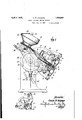
Further objects and advantages will appear from. a more complete'description of a duplexeyeleting machine embodying the invention disclosed in the accompanying drawings in which I LA Figure -1 is a left side elevation of the machine.
Figure 1a is a detail inperspective. I t Figure 2 is a right side elevation of the machine.
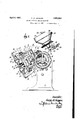
' Figurefiis atop plan of the machine.
Figure is a detail section through: the punching mechanism and work support.
Figures 5 and. Gare sectional details of the supply hopper and drivemechanisnn the drive parts being shown in different posi- V tions. p
Figure 7 1s a section on line 7-7ofF1gure 1.
' and pin indifferent positions.
. of Figure ,2.
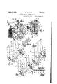
Figures 8 and 9 are details of the stop cam Figure 10 is a fragmentary front elevation of the machine. I
Figure llis a detail section on-line 1111" Figures 12, 13 and 14 aredetails showing the relative positions of raceways, punches and sets during successive stages of the cycle of operation. T
Figure 15"is a sectional detail showing a modification.
. As best shown in Figures 1; 2, and3, the
operative mechanisms are carried entirely by a slngle upstanding web 1 havlng a supporting foot 2 at its lower end by which it" may be carried onia suitable bench or platform. The upper end portion of the web 1 integral pins 10 to end flanges 11 of a tool supporting block or carrier indicated as a Whole at 12. I This block is provided with spaced arms leihaving enlarged head por tions15 at. their ends through which are upper and lower sets 19' and 20. The arms l l are joined by a web 21. The pivots 10 not only connect the links 7 to the arms 14, but they also pivotally connect these members with'upper and lower levers 25, the rearends of which are pivotedby the screws 26 to up I per and lower bearing bosses 27 carried by the web 1 and extending within a transverse opening 28 therethrough." The pivot screws 26'form1the pivotal center for the. feed motionof the. work, as will later appear, and V the levers 25 are swung backwardly and forslidably mounted in opposed relation, the 1 upper and lower punches 17 and 18 and the wardly as the feed frame 6 is reciprocated on the guide pins 5, the links 7 permitting the rectilinear motion of the feed frame to impart the desired swinging motion to the levers 25 without binding of the parts.
As will be seen from an inspection of Figures 12, 13 and 14, the tool-supporting block has a pivotal motion about the pins 10 which permits it a motion in addition to the feed motion produced by swinging of the levers 25. This pivotal motion is for the purpose of bringing the punches and sets alternately into operative relation to the work. For controlling this motion, the arms 14 are extended rearwardly of the pivot 10 and are provided with wear pieces 85 which are normally pressed into engagement with the ends of adjusting wear screws 36 extended through flanges 37 in the sides of the arms 25, the screws 36 being held in adjusted position as by means of the lock nuts 38. Such pressing together of these partsis efiected by means of the springs l0 reacting between pins 41 on the arms 14 and pins 12 positioned centrally in the pivot pins 8. When the stops are in contact, the punches are in operative position. But at suitable times, as will later appear, the tool block is swung about the pivots 10 to bring the sets into operative position.
The feed frame 6 is given its traversing motion by means of a cam positioned on the forward end of a cam shaft 51 which is journaled in bosses 52 and 53 projecting from one side of the web 1, the shaft 51 being arranged in a forwardly and downwardly inclined position. The cam 50 is provided with a face cam groove 55 within which rides a follower 56 on a lever 57, this lever being pivoted at 58 to a portion 59 projecting laterally from the web 1, as shown in Figure 11. The lever 57 is provided with a longitudinal slot within which rides a block 60 carried by a pin 61 journaled in and projecting inwardly from an adjustment slide 62 (see Figure 10) this slide having an integral portion projecting through a slot 64 in the feed frame. The pin 61 is held to the slide 62 by a screw 63 (Figure 10). By adjustment of the block 62 lengthwise of the feed frame, the distance of the block 60 from the fulcrum of the lever may be adjusted thus to change the effective throw of this lever to actuate the feed frame.
Both layers of work in which the fasteners are to be set are placed upon the work support 70, which is fixed to a bracket 71 extending laterally from the supporting web 1, a spring presser foot 7 2 carried by the work support holding the work in place thereon. As shown best in Figures 3 and 4, this work support and press-er foot are each provided with a slot or clearance space 73 within which the punch mechanism may operate during the punching and feeding movements. As shown in Figure 4., the lower punch 18 is provided at its upper end with a removable anvil 75 fixed by a threaded retaining collar 76 to the shank portion of the punch, which for the punching operation is moved upwardly into the clearance space 73 at the same time that a hollow cutting punch 77 carried by the upper punch ing device descends and cuts through the work against the anvil 75. An opening 78 through the cutting punch 77 and opening laterally through the side of its supporting shank portion permits the escape of the punchings. Through the action of the cam 50 the punches are then moved laterally to feed the work, and to bring the setting devices in line with the last eyelet in the raceway 80, as shown in Figure 13. The sets are shown as of usual form each being provided with a central spindle which may engage within the eyelet barrel to remove it from the raceway and present it to the hole in the work.
The sets having been moved toward each other to take the eyelets from the raceway, means are provided for rocking the punch and set carrier, so that the eyelets are presented to the holes punched in the work, whereupon the sets are actuated to set the eyelets therein. This movement of the punch and set carrier to present the eyelets to the work is effected by means of a rod 82 slidable through the web member 1. and having at its rear end a cam follower 83 engaging in an edge cam groove 84 in a cam 85 also carried by the shaft 51. The outer end of the rod 82, when this rod is pushed outwardly by the action of the cam 85, impinges on the web 21 of the block 12, thus rocking this block about the pivot 10 against: the tens on of the springs 40. As shown also, the outer end of the rod 82 carries an anvil plate 88 adapted to be interposed between the setting devices so that the eyelets are clinched thereagainst. The rod 82 is then drawn backward, the levers 25 swung back to starting position, the position of the feed block 62 detern'iining how far back of the final setting posit on this start-ing position is situated. thus determining the spacing between the eyelets. Instead of carrying the anvil plate by the rod 82, it may be carried by the tool block 12 being so shown in 89 in Figure 15.
The punches and sets are reciproeated toward and from each other and both l'QliltlX't-Z to the work support to effect the punch ng and setting actions, their motions toward each other being produced by the rocking of a pair of hammers 90 pivoted at. 91 to the web 1 and having connected to the opposite ends of their pivots, arms 92 provided with intermeshing gear segments 93 at their adjacent ends, whereby ntion of one hammer causes opposite simultaneous motion of the other. One of the arms 92, herein shown the lower arm, has a rearward extension94 provided with a cam follower 95 which rides in a groove in a cam 96 keyed to the main drive shaft 97 of the machine The shaft 51 is driven from this main shaft through a 98 and 99011 these respective shafts,
Each oft'he hammers 90 has an adjustable head portion 100 which bears on the punches and actuates them fortheir punching stroke,
is axially moved at any one time.
It will be noted that the layers of work are punched together by punching means common to both while they rest in superposed relation and in contact on the upper face of 1 a work support and that thereafter an individual fastener set in each of the two layers of work in the holes so punchedby a setting 1 device individual for each of the two layers and an anvil'placed between the layers'and' devices cooperate.
with opposite faces of whichthe two setting DTiLWiILf] (m d -stop mechanism The drive shaft97' is shown as driven by a belt pulley 120 journaled thereon (see Fig-' ure 7) which is provided in a hub portion 121 with a clutch face 122whichcooperates with a mating clutch I face on a clutch collar 123 slidable on the shaft 97 into and out of clutch ing relation with the pulley clutch face. The opposite end of the clutch collar 123 from the pulleygwhen moved out; of clutching relaawav from the web 11 and toward thc bolt' tion to the pulley, bears'throug'h' a pad-124 of frictional material against a. plate 125. This plate is-slidablv guided on bolts 12'? which hold it against rotation, coil-springs 126 surrounding these bolts pressing theplate headsand tending; to hold the collar 128 in clutching engagement-with the pulley This clutch collar, however. has'a cam face member shown detached in Figures 8 and 9 at 128 with which cooperates the upper end of a rod 129 vertically slidable througha bracket 130 carried by the webmember 1. hen the rod 129 is'moved upwardly to br ng its inner end into the groove] 31'of the clutch collar at a suitable angularpositiomthecam member 128 rides thereagainst as shown ure 8, this acting to ni'ovethe clutch colout of clutching position, as shown in 7 and bringing'the clutch collar into lar Figure brakingrelation-to the plate 125, thus tending to stop rotation of this 'COll-:Il-&11(.lill
pair of spiral gears spacing collars 1G1.
wise rotation of the shaft, 97 with which itjis keyed. At. the same time, the plate 125 which has fixed thereto a brake disk is moved over toward the web member '1 so as to bring this brake disk 135, againstthe outer face of v the cani96, thus effecting a braking action;be-- tween the cam 96 and the plate 125, as well as between the clutch collar 131 and this plate.
The axial thrust ofthese members is taken 'upby the thrust ball bearingshown at1861 Just before the stopping of the shaft 977 however,- the depression 138 in the cam meme is J her 128 comes opposite to the rod;129 as; i
shown in Figure 9, thus permitting the plate; 125 to spring backqslightly under the action of the sorin s 126 but not sufiicient to brin L b 7 i D i the clutch collar 131 into clutching relation with'the pulley. This motion is sufficient, 5
however, to relieve th-epressure of the brake disk 135 on the cam 96, thus to reduce the braking effort on theshaft 97 so that it may be turned by hand as by means of the hand wheel 140 after the machine has been stopped, This depression 138 also performs the function oftending to prevent rebound when therotation of the, clutch collar is final-i ly positively stopped byimpiiigement of thev shoulder 142 onithe cam member 128 against the rod129.
lnorder that the shaft 97 maybe turned by hand, it is necessary that'the rod 129 should be retractedfrom the cam 128, but invorder that this may be done without. causing spring-S 126 to move theclutchcollar into clutching position with the pulley 102, a lock ing rod 144 is provided whichmay be prov jected' upwardly by any suitable means, asby a rocking handlever 145, in frontof a flange,
146 on the inner end of the clutch collalr,-th,us to prevent the clutchcollar from beingreturned by'the springs 126 when the rod 129' is retract-ed. As shown (see Figures 1 and 1a) a pin 147 is eccentrically disposed to the pivotal axis 148 of the lever'145, and engages between spaced pins1149 carried by'the rod 144. The rod144 may be held in the desired position by engagement of a spring pressed locking dog 150carried by the lever 145 in either of a pair of'notches as 151 in the edge of a fixed disk 152. The rodi129, as shown inFigure 1, may have a hooked rod 156 attached thereto by which'it maybe depressed, if desired, as by means of a foot treadle (not shown).
Fastener feed mechanism T The raceways 80, hereinbefore referred to,
and from thelowerends of which theeyelets i are picked 011' by the sets, are'held at their lower 'ends in parallel spaced relation, as
shown in Figure-11, as by screws 160 and as a unit toward andfroin theweb member: 1, forithis purpose the lowerraceway has aslot They may be adjusted W 182therein eng'agingover the head 1680f an E I adjusting screw 16% threaded into the bracket block 71 fixed to the web member 1, to which block is also fixed the rear end of the work support.
Above its lower end the upper raceway is given a half twist as shown in Figures 1 and 3, so as to reverse the position of the eyelets therein as they are taken from the hopper, the upper raceway presenting the eyelets to its setting mechanism with the flange upwardly disposed and the lower raceway presenting its eyelets to the lower setting mechanisms with the flange lowermost. The upper ends of the raceways pass about opposite sides of the supply hopper 170 to which they are made fast, the supply hopper and the raeeways forming together a unit mechanism which may be removed and replaced upon the machine as a whole.
The hopper device has a base comprising a disk shaped plate 17 2 through which is journalled a shaft 173 carrying at its upper end a circular agitating brush holder 17 1. The lower end of this shaft 173 is provided with a head 175 with a rib 176 diametrically arranged thercon. This head 175 is seated within a socket portion 177 at the lower end of a hub portion 178 of the disk 172, this socket being so formed as to partially surround and be held rearwardly by its engagement with the head 180 of a driving shaft 181, this hub having a notch 182 within which the rib 176 fits. This shaft 181 extends through a worm gear 183 having a hub 184 journaled in a bracket member 185 carried by the web 1, and it is arranged to be rotated by means of a. worm 186 on a worm shaft 187 journaled in this bracket and provided at one end with a belt pulley 188 by which it may be driven by a belt passing over one of the two belt grooves in the main drive pulley 120. The worm wheel 183 is arranged to be clutched to the shaft 181 to drive the latter, and thus transmit rotation to the brush holder 17 4, by means of a cluch mechanism com prising a transverse pin 190 passing through the shaft 181 and, when in driving relation, resting in a. notch 191 in the lower face of the hub 184 of the worm wheel. It may, however, be moved out of this notch by axial movement imparted to the shaft 181. It will be normally held therein, however, by a coil spring 103 surrounding the shaft 181 and bearing between its head 180 and wall portion 195 at the end of the worm wheel hub, the spring thus being seated in a socket in the Worm wheel.
For the purpose of withdrawing the pin 190 from engagement in the slot 191, the lower end of the shaft 181 is grooved as at 196 and riding in this groove are spaced alined pins 197 projecting from the end of the lever 198 which is journaled on a screw 199 fixed to a portion of the bracket 185. The head of the screw 199 may be provided with a notch 200 within which may be engaged a dog 201 pivoted at 202 to the lever 198, this dog being pressed by the spring 203 to engage in this notch whenever the lever 198 is rocked to the proper position. When in this position, to which it may be moved manually, the dog engages in the notch and holds the lever against turning with the pin 190 out of clutching relation, thus disconnecting the rotary drive for the brushes. This disconnection, however, is accomplished independently of the disconnection afforded through the engagement between the rib 17 0 and the notch 182, it being possible at any time to raise up the hopper and the raceways fixed thereto and remove them from the machine since they merely rest by gravity in position thereon.
The hopper 170 is provided with openings 205 on opposite sides of the cylindrical lower wall portion 206 to permit the escape of eyelets therefrom in proper position into the raceways. Above the lower portion the hopper walls are shown as flared outwardly at 207 to form a larger upper chamber or receptacle from which the eyelets may pass in a somewhat restricted manner to the lower portion of agitator chamber past a partition plate 208 which has an arcuate slot 209 therein through which the eyelets pass. This plate bridges the small diameter lower portion of the hopper and serves to hold back the large mass of eyelets in the upper large portion of the hopper to keep their weight away from the brushes which might prevent the brushes properly agitating and turning the eyelets so as to present them in proper position to escape to the raeeways.
At the upper portion of the hopper is shown a cover 209 having a spring latch 210 thereon, which cover may be opened whenever it is desired to replenish the hopper with eyelets. The plate 208 also may be moved to facilitate the removal of eyelets from the lower chamher as when a change of eyelets is desired, it being shown as held in position adjacent to. the lower end of the flaring portion of the hopper by means of a spring 215 surrounding a central stem 216, the spring reacting between the plate 208 and the upper wall of the hopper and having at its upper end a head 218 projecting above the hopper which may be grasped and raised when it is desired to lift the plate 208 from its seated position.
While this invention has been shown embodied in a'machine for setting eyelets, it should be understood that except as specifically stated in the appended claims, it is not limited to the setting of eyelets or other fasteners of the barrel type, that is, which have tubular shank portions which pass through the 1 work, and it should also be evident that various changes and modifications might be made therein without departing from the spirit or scope of this invention as defined by the appended claims.
fastener from said racewayand set it in the hole punched. ,2. Ina machine ofthe class described, a punch, a set, a carrrier for said punch. and set,jm'eans toactuate. said pnnch and set to punch the work and then set fasteners in the work, and means acting between the punch and set actuations to move said carrier first to feed the work and then to bring said set with a fastener thereon into .alinement with the punched hole.
3. In a machine of the class described, a
punch, a'set, a carrier for said punch and set,
support, then to movelaterallyto feed the Work oversaid support while in engagement 'with said punching devices, then to take a means for moving said carrier while the punch is in operative position to feed the work, and means for thereafter moving said carrier to bring said set into operative position.
I. In a machine of the class described, a punch, a set, a carrier for said punch and set, a feed member pivotally supporting said carrier, means for moving said feed member to move said carrier to feed the work, and means for swinging said carrier relative to said feed member to bring the punch and set alternately into operative position. I
5. In a machine .of the class described, a punch, a set, a carrier for said punch and set,
. a feed leverto which said carrier is pivoted,
means for swinging said lever to effect feed of the work, and means for swinging said carrier about its pivot on said lever to bring said punch and set alternately into operative position. I
6.- In a machine of the class described, a punch, a set, a carrier for said punch and set, a pair of feed levers between which said carrier is pivoted, means for swinging said levers to effect feed of the work, and means for swinging said carrierabout its pivot onv said levers to br1ng said punch and set alternately into operative position.
7 In a machine forv setting barrel fasteners, punching and setting devices, a stationary fastener presenting raceway, a work support, and means to actuate said devices to cause sald punch to cut a l10l6 111 the work, then to move said devices laterally to feed the work over said support, then to take a barrel fastener fromsaid stationary raceway and set it in the hole cut in the work, and then to return said devices to initial positions.
8. In a machine of the class described, oppositely disposed punching devices and oppositely disposed setting devices, a pair of raceways for presenting a pair of fasteners simultaneously, a work support, and means to actuate such devices to cut holes simultaneously in a pairof layers of work on said pair of fasteners from said raceways, and then to set both'of-said fasteners simultaneously each inthe hole .ofone of said layers of work. a I I 9. In a machine ofxthe class described, a frame, av slide movable rectilinearly on said frame, a tool carrier pivotally connected to said frame, operative connections between said "slide and carrier,,and means for moving aid slide to effect work feeding and retractingmovement of'said, tool carrier.
11. In a machine of the class described, a' frame, a slide movable rectilinearly on said frame,'a tool carrier, a pair of levers each pivoted atone end to said frame and connected to sa d carrier at their other ends, operative connections between said slide and car rier, and means for effecting work feeding. and. retracting movement of said tool carrier.
; 12. Ina machine of theclass described, a
frame,a slide movable rectilinearly on said frame, a tool carrier pivot-ally connected to saidframe and to said slide, and means for movlng saidslide to effect work feed ng and retracting movement of said tool carrier. Y
13. In a machine of the class described, a f
frame, a slide movable rectilinearly on said frame, a tool carrier, a lever pivoted to said! frame and connected to said carrier, pivoted l nk connections between. said sl de and car.- rier, and means for-moving said slide to effectwork feeding and. retracting movement of said tool carrier. a g 14. In a machine of the class described, a frame, a slide movable rectilmearly on said frame, a tool carrier, a pair of levers each" pivoted at one end to said frame and connect ed to said carrier at their other ends, links pivoted at opposite ends to said slide and carrier, and means'for moving said slide to efiect work feeding and retracting movement of said tool carrier. 7 v
.15. In a machine ofthe class described, av slide, alever, a block carried b-ysaid slide and engagingsaid lever and adjustable toward and from itsfulcnun by movement relative to said slide, a pivotallymounted tool can rier, operative connections between said slide and carrier, and means for swinging said leverto effect movements of said carrier of amplitude determined by the position of said block relative to saidv slide.
a machine f the class described, a.
punch and a set, a carrier for said punch and set, a feed member pivotally supporting said carrier, cooperating stops on said member and carrier, a spring for holding said stops in contact with said punch in operative position, means for moving said feed member to feed work, and means acting at a suitable time in the cycle of operations to swing said carrier relative tosaid member to bring said stops out of contact and to present said set in operative position.
17. In a machine of the class described, devices comprising a punch and a set, a carrier for said devices, a feed member pivotally supporting said carrier, cooperating stops on said member and carrier, a spring for holding said stops in Contact and with one of said devices in operative position, means for moving said feed member to feed work, and means acting at a suitable time in the cycle of operations to swing said carrier relative to said member to bring said stops out of contact and to present the other of said devices in operative position.
18. In a machine of the class described, apunch and a set, a carrier for said punch and set, a feed member pivotally supporting said carrier, cooperating stops on said member and carrier, a spring for holding said stops in contact with said punch in operative position, means for moving said feed member to feed work, an anvil, and means acting at a suitable time in the cycle of operations to swing said carrier relative to said member to bring said stops out of contact to present said set in operative position, and to present said anvil into cooperative relation to said set.
19. In a duplex machine of the class described, a work support having a slot therein, a presser foot for holding a pair of layers of work on said support, a pair of cooperating punching members movable toward and from each other and both relative to said work support at a certain portion of said slot to punch the work and movable lengthwise of said slot to feed the work, and means for setting a fastener in the holes made by the punching means in each of said pair of layers of work.
20. In a duplex machine of the class described, a support for two layers of work, a pair of cooperating punching members one above and the other below the work-supporting face of said support, said punching members being movable toward each other and both relative to said work support to punch both layers of work resting on said support, and means for setting a fastener in the holes made by the punching means in each of said two layers of work.
21. In a duplex machine of the class described, a support for two layers of work, a pair of cooperating punching members one above and the other below the work-supporting face of said support, said punching memsignature.
GEORGE W. JACQUES.
Priority Applications (1)
| Application Number | Priority Date | Filing Date | Title |
|---|---|---|---|
| US218458A US1852849A (en) | 1927-09-09 | 1927-09-09 | Duplex fastener setting machine |
Applications Claiming Priority (1)
| Application Number | Priority Date | Filing Date | Title |
|---|---|---|---|
| US218458A US1852849A (en) | 1927-09-09 | 1927-09-09 | Duplex fastener setting machine |
Publications (1)
| Publication Number | Publication Date |
|---|---|
| US1852849A true US1852849A (en) | 1932-04-05 |
Family
ID=22815201
Family Applications (1)
| Application Number | Title | Priority Date | Filing Date |
|---|---|---|---|
| US218458A Expired - Lifetime US1852849A (en) | 1927-09-09 | 1927-09-09 | Duplex fastener setting machine |
Country Status (1)
| Country | Link |
|---|---|
| US (1) | US1852849A (en) |
-
1927
- 1927-09-09 US US218458A patent/US1852849A/en not_active Expired - Lifetime
Similar Documents
| Publication | Publication Date | Title |
|---|---|---|
| US1721276A (en) | Die-shearing press | |
| US1852849A (en) | Duplex fastener setting machine | |
| US2179900A (en) | Rivet setting machine | |
| US2061193A (en) | Setter for snap fasteners | |
| US1454841A (en) | Feeding mechanism for dieing and other machines | |
| US1834919A (en) | Machine for ornamenting shoe parts | |
| US1792051A (en) | Apparatus for sizing bushings | |
| US1962715A (en) | Vibrating riveter control | |
| US1778956A (en) | Automatic machine for making metal plugs for barrels | |
| US1049463A (en) | Machine for setting fasteners. | |
| US1132988A (en) | Riveting-machine. | |
| US1839048A (en) | Rivet setting machine | |
| US1924982A (en) | Fastener setting machine | |
| GB382643A (en) | Improvements in machines for setting fasteners | |
| US1019005A (en) | Machine for punching and feeding sheet material. | |
| US441388A (en) | Erett m | |
| US2324482A (en) | Clutch throwout mechanism | |
| US845714A (en) | Sole-pressing machine. | |
| US2065621A (en) | Machine for operating upon sheet materials | |
| US704356A (en) | Button-machine. | |
| US443570A (en) | Punching and eyeleting machine | |
| US703573A (en) | Stitch-separating machine. | |
| US259100A (en) | Eyeleting-machine | |
| US1041343A (en) | Automatic drill. | |
| US1798969A (en) | Button-attaching machine |