US1852844A - Tool joint - Google Patents
Tool joint Download PDFInfo
- Publication number
- US1852844A US1852844A US230492A US23049227A US1852844A US 1852844 A US1852844 A US 1852844A US 230492 A US230492 A US 230492A US 23049227 A US23049227 A US 23049227A US 1852844 A US1852844 A US 1852844A
- Authority
- US
- United States
- Prior art keywords
- protector
- joint
- drill pipe
- tool joint
- box
- Prior art date
- Legal status (The legal status is an assumption and is not a legal conclusion. Google has not performed a legal analysis and makes no representation as to the accuracy of the status listed.)
- Expired - Lifetime
Links
- 230000001012 protector Effects 0.000 description 25
- 238000010276 construction Methods 0.000 description 5
- 238000005553 drilling Methods 0.000 description 2
- 239000003129 oil well Substances 0.000 description 1
- 230000000630 rising effect Effects 0.000 description 1
- 239000004576 sand Substances 0.000 description 1
Images
Classifications
-
- E—FIXED CONSTRUCTIONS
- E21—EARTH OR ROCK DRILLING; MINING
- E21B—EARTH OR ROCK DRILLING; OBTAINING OIL, GAS, WATER, SOLUBLE OR MELTABLE MATERIALS OR A SLURRY OF MINERALS FROM WELLS
- E21B17/00—Drilling rods or pipes; Flexible drill strings; Kellies; Drill collars; Sucker rods; Cables; Casings; Tubings
- E21B17/10—Wear protectors; Centralising devices, e.g. stabilisers
- E21B17/1057—Centralising devices with rollers or with a relatively rotating sleeve
-
- E—FIXED CONSTRUCTIONS
- E21—EARTH OR ROCK DRILLING; MINING
- E21B—EARTH OR ROCK DRILLING; OBTAINING OIL, GAS, WATER, SOLUBLE OR MELTABLE MATERIALS OR A SLURRY OF MINERALS FROM WELLS
- E21B17/00—Drilling rods or pipes; Flexible drill strings; Kellies; Drill collars; Sucker rods; Cables; Casings; Tubings
- E21B17/10—Wear protectors; Centralising devices, e.g. stabilisers
- E21B17/1042—Elastomer protector or centering means
-
- E—FIXED CONSTRUCTIONS
- E21—EARTH OR ROCK DRILLING; MINING
- E21B—EARTH OR ROCK DRILLING; OBTAINING OIL, GAS, WATER, SOLUBLE OR MELTABLE MATERIALS OR A SLURRY OF MINERALS FROM WELLS
- E21B17/00—Drilling rods or pipes; Flexible drill strings; Kellies; Drill collars; Sucker rods; Cables; Casings; Tubings
- E21B17/10—Wear protectors; Centralising devices, e.g. stabilisers
- E21B17/1057—Centralising devices with rollers or with a relatively rotating sleeve
- E21B17/1064—Pipes or rods with a relatively rotating sleeve
Definitions
- My invention relates to improvements in tool joints, and particularly to joints employed for connecting sections of drill pipe employed in drilling wells.
- both the joints and the casing in which the drill pipe operates are subjected to considerable wear.
- One of the main objects of the present nvention is to provide a joint havlng protector means for preventing wear on the joint as well as on the casing, said protector or wearing means being of such a character that they may be readily replaced when worn.
- a further object is to provide a joint embodying protector means of such a character that the drill pipe sections to'which the joint is applied will not be injured.
- Fig. 1 is a vertical sectional view of a tool joint embodying my invention, said joint being shown in asection of the casing;
- Fig. 2 a horizontal sectional view, the section being taken on line II-II of Fig. 1;
- Fig. 3 a view similar to Fig. 1, showing a modified form of protector means employed in connection with the joint; and j,
- Fig. 4 a vertical sectional view of a joint comprising the box and pinmembers, each having protector receiving means shown in connection therewith, vthe protector means being omitted.
- Fig. 1, 5 designates a sectionof ⁇ a casing of the character employed in oil and gas wells
- [40. and 6 and 7 respectively designate sections of a drill pipe of the form usually employed in rotary well drilling operations.
- the tool joint includes a box-member 8 and a pin- -member 9, each provided adjacent the joint therebetween with a grip portion 3 and 4 respectively lfor a ⁇ tong.
- Box-member 8 is formed hollow, and is provided with an in-y ternally threaded tapered portion 10 adapted to receive the threaded end portion 11 ,of the rollers and the outer made of some suitable rubber.
- the protector 22 is positioned ony In addition to the parts just mentioned, pin
- member 9 is provided adjacent the grip portion 4 with an outwardly projecting annular flange 15 and a hollow cylindrical extension 16, said extension being formed at its lower end with threads 17.
- the extension 16, t0- gether with the-annular flange 15, constitutes protector receiving means, the latter being designed to be mounted thereon and be maintained in the desired operative position by means of a locking member, as, for example, a threaded ring member 18 designed to be attached to the lower threaded portion 17 of the said extension 16.
- the protector designated generally by the numeral 19, includes a series of rollers 20 and a freely rotatable collar or sleeve 21, rollers 20 extending vertically of the protector receiving means and being interposed between the outer Iace of the cylindrical eXtension 16 and the sleeve 21. From the above, it will be understood that the protector is maintained in operative position on the exf tension by means of the flange 15 and the locking means 18.
- the pin member of the joint is of substantially the same con- 4.
- a tool joint comprising struction as in the other forms described.
- I have shown protector ing adjacent the joint therebetween a grip receiving means formed on the box-member portion for a tong, one of said members hav- 8a, and for this purpose, have provided the ing integrally formed therewith a cylindrical 70 box-member 8a with an annular flange 15a extension adapted to telescope over the end and with an upper exteriorly threaded porof a drill pipe and a protector rotatably tion 23 adapted to receive an internally mounted on said cylindrical extension. threaded ring 24.
- . tector means may be applied to either the pin-member or the box-member of the tool joint, or to both, if so desired.
- the protector means may be readily applied to or removed 80 from the joint structure and that the construction provides simple and edeetive means for preventing wear of both the joint and the casing in which the drill pipe operates. It will also be noted that the construction pere5 mits the sections of drill pipe to be connected and disconnected inthe usual manner, and that the drill pipe sections will not be injured due to sand, etc. working into and perhaps temporarily affecting the proper functioning eo of the protector means, and, further, that the said protector means are not directly connected with the drill pipe sections.
- rIhe outer diameter ⁇ of the protector means 3 is greater than the diameter of the joint propa5 er and slightly greater than the projecting iiange of the joint. Consequently, 'the protector will, as thedrill pipe is operated and swings in the casing or hole, act as an antifriction bearing means. 20o
- a tool joint comprising interitting box and pin members each having adjacent the joint therebetween a 'grip o portion for a tong, one opt said members havl05 ing integrally formed therewith a cylindrical extension adapted to telescope over the end of a drill pipe and a protector mounted on said cylindrical extension.
- a tool joint comprising Y10 a box member and a pin member each having adjacent the joint therebetween a grip portion for a tong and each having a threaded bore for engaging the threaded end of a drill ipe, one of said members having integrally "-15 ormed therewith a cylindrical extension adapted to telescope-over a drill pipe engaged by said member, and a protector mounted on said cylindrical extension.
- a tool joint com rising l2() a box member and a pin member each aving adjacent the joint therebetween a grip portion for a. tong and each having a threaded bore for engaging the threaded'end of a drill pipe, one of said members having integrally 5 formed therewith a cylindrical extensionr adapted to telescope over a drill pipe enga ed by saidy member, and a protector rotataly y ⁇ mounted on roller bearings on said cylindrical extension.
Landscapes
- Engineering & Computer Science (AREA)
- Life Sciences & Earth Sciences (AREA)
- Geology (AREA)
- Mining & Mineral Resources (AREA)
- Mechanical Engineering (AREA)
- Physics & Mathematics (AREA)
- Environmental & Geological Engineering (AREA)
- Fluid Mechanics (AREA)
- General Life Sciences & Earth Sciences (AREA)
- Geochemistry & Mineralogy (AREA)
- Earth Drilling (AREA)
Description
E. E. GREVE April 5, 1932.
TOOL. JOINT v Filed NOV-'2, 1927 61H01 ML,
Patented Apr. 5, 1932 UNITED STATES PATENT OFFICE EDGAR E. GBEVEOF BELLEVUE, PENNSYLVANIA, ASSIGNOR, BY MESNE ASSIGNMENTS, F PITTSBURGH, PENNSYLVANIA, A CORPORA` TO OIL WELL SUPPLY COMPANY, TION 0F NEW JERSEY TOOL JOINT l 4 .Application led November 2, 1927. Serial No. 230,492.
My invention relates to improvements in tool joints, and particularly to joints employed for connecting sections of drill pipe employed in drilling wells.
5 In the use of these joints, both the joints and the casing in which the drill pipe operates are subjected to considerable wear. One of the main objects of the present nvention is to provide a joint havlng protector means for preventing wear on the joint as well as on the casing, said protector or wearing means being of such a character that they may be readily replaced when worn. A further object is to provide a joint embodying protector means of such a character that the drill pipe sections to'which the joint is applied will not be injured.
Other objects and advantages of the invention will be pointed out or become apparent from a consideration of the following description taken in connection with the accompanying drawings.
In the drawings:
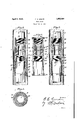
Fig. 1 is a vertical sectional view of a tool joint embodying my invention, said joint being shown in asection of the casing;
Fig. 2, a horizontal sectional view, the section being taken on line II-II of Fig. 1;
Fig. 3, a view similar to Fig. 1, showing a modified form of protector means employed in connection with the joint; and j,
Fig. 4, a vertical sectional view of a joint comprising the box and pinmembers, each having protector receiving means shown in connection therewith, vthe protector means being omitted.
Referring to the drawings, and first to Fig. 1, 5 designates a sectionof `a casing of the character employed in oil and gas wells, [40. and 6 and 7 respectively designate sections of a drill pipe of the form usually employed in rotary well drilling operations.
The tool joint, as illustrated and as preferred, includes a box-member 8 and a pin- -member 9, each provided adjacent the joint therebetween with a grip portion 3 and 4 respectively lfor a` tong. Box-member 8 is formed hollow, and is provided with an in-y ternally threaded tapered portion 10 adapted to receive the threaded end portion 11 ,of the rollers and the outer made of some suitable rubber. The protector 22 is positioned ony In addition to the parts just mentioned, pin
As illustrated in the form of Fig. 1, the protector, designated generally by the numeral 19, includes a series of rollers 20 and a freely rotatable collar or sleeve 21, rollers 20 extending vertically of the protector receiving means and being interposed between the outer Iace of the cylindrical eXtension 16 and the sleeve 21. From the above, it will be understood that the protector is maintained in operative position on the exf tension by means of the flange 15 and the locking means 18.
In the form of Fig. 3, the construction of the joint is identical with the construction shown in the form however, in this latter form dii'ers somewhat from the protector means shown in the form of Fig. 1. In theform of Fig. 3, in place sleeve, I employ as the protector or anti-friction means an of Fig. 1. The protector,
elongated rotatable collar 22, preferably yielding materia-l, as
the extension'l and maintained thereon between the flange 15 and the locking ring 18 in the same manner in which the other protector means are maintained.
In the forni of Fig. 4,the pin member of the joint is of substantially the same con- 4. In combination, a tool joint comprising struction as in the other forms described. In intertting box and pin members each havthis form, however, I have shown protector ing adjacent the joint therebetween a grip receiving means formed on the box-member portion for a tong, one of said members hav- 8a, and for this purpose, have provided the ing integrally formed therewith a cylindrical 70 box-member 8a with an annular flange 15a extension adapted to telescope over the end and with an upper exteriorly threaded porof a drill pipe and a protector rotatably tion 23 adapted to receive an internally mounted on said cylindrical extension. threaded ring 24. By the employment of In testimony whereof I aix my signature. 1 this construction, it will be seen that the pro- EDGAR E. GREVE. 75
,. tector means may be applied to either the pin-member or the box-member of the tool joint, or to both, if so desired.
It will be understood that the protector means may be readily applied to or removed 80 from the joint structure and that the construction provides simple and edeetive means for preventing wear of both the joint and the casing in which the drill pipe operates. It will also be noted that the construction pere5 mits the sections of drill pipe to be connected and disconnected inthe usual manner, and that the drill pipe sections will not be injured due to sand, etc. working into and perhaps temporarily affecting the proper functioning eo of the protector means, and, further, that the said protector means are not directly connected with the drill pipe sections.
rIhe outer diameter` of the protector means 3 is greater than the diameter of the joint propa5 er and slightly greater than the projecting iiange of the joint. Consequently, 'the protector will, as thedrill pipe is operated and swings in the casing or hole, act as an antifriction bearing means. 20o
I claim: l. In combination, a tool joint comprising interitting box and pin members each having adjacent the joint therebetween a 'grip o portion for a tong, one opt said members havl05 ing integrally formed therewith a cylindrical extension adapted to telescope over the end of a drill pipe and a protector mounted on said cylindrical extension.
2. In combination, a tool joint comprising Y10 a box member and a pin member each having adjacent the joint therebetween a grip portion for a tong and each having a threaded bore for engaging the threaded end of a drill ipe, one of said members having integrally "-15 ormed therewith a cylindrical extension adapted to telescope-over a drill pipe engaged by said member, and a protector mounted on said cylindrical extension.
3. In combination, a tool joint com rising l2() a box member and a pin member each aving adjacent the joint therebetween a grip portion for a. tong and each having a threaded bore for engaging the threaded'end of a drill pipe, one of said members having integrally 5 formed therewith a cylindrical extensionr adapted to telescope over a drill pipe enga ed by saidy member, and a protector rotataly y `mounted on roller bearings on said cylindrical extension. 130
Priority Applications (1)
| Application Number | Priority Date | Filing Date | Title |
|---|---|---|---|
| US230492A US1852844A (en) | 1927-11-02 | 1927-11-02 | Tool joint |
Applications Claiming Priority (1)
| Application Number | Priority Date | Filing Date | Title |
|---|---|---|---|
| US230492A US1852844A (en) | 1927-11-02 | 1927-11-02 | Tool joint |
Publications (1)
| Publication Number | Publication Date |
|---|---|
| US1852844A true US1852844A (en) | 1932-04-05 |
Family
ID=22865440
Family Applications (1)
| Application Number | Title | Priority Date | Filing Date |
|---|---|---|---|
| US230492A Expired - Lifetime US1852844A (en) | 1927-11-02 | 1927-11-02 | Tool joint |
Country Status (1)
| Country | Link |
|---|---|
| US (1) | US1852844A (en) |
Cited By (1)
| Publication number | Priority date | Publication date | Assignee | Title |
|---|---|---|---|---|
| US3999618A (en) * | 1975-01-22 | 1976-12-28 | Smith International, Inc. | Hammer stabilizer |
-
1927
- 1927-11-02 US US230492A patent/US1852844A/en not_active Expired - Lifetime
Cited By (1)
| Publication number | Priority date | Publication date | Assignee | Title |
|---|---|---|---|---|
| US3999618A (en) * | 1975-01-22 | 1976-12-28 | Smith International, Inc. | Hammer stabilizer |
Similar Documents
| Publication | Publication Date | Title |
|---|---|---|
| US4380347A (en) | Well tool | |
| US3978933A (en) | Bit-adjacent stabilizer and steel | |
| US3764168A (en) | Drilling expansion joint apparatus | |
| GB1461003A (en) | Dual concentric drill pipe | |
| US5261498A (en) | Drill string component | |
| US2624549A (en) | Method and means of rotary drilling | |
| US1876627A (en) | Multiple pipe unit adaptable to the drilling and pumping arts | |
| US2288124A (en) | Drilling string protector | |
| US2368415A (en) | Drill pipe protector | |
| US4919202A (en) | Sucker rod guide bearing | |
| US1474905A (en) | Tool joint | |
| US2325132A (en) | Protector for drill stems | |
| US2708100A (en) | Safety joint for oil well drilling stems | |
| US2664272A (en) | Coupling | |
| US1839690A (en) | Twist-off safety coupling | |
| US2507849A (en) | Swivel | |
| US1852844A (en) | Tool joint | |
| US2325811A (en) | Drilling sleeve | |
| US2513621A (en) | Tool joint wear collar | |
| US1265706A (en) | Collar and lead ring and process of coupling drill-pipes. | |
| US1824257A (en) | Tool joint | |
| US2592854A (en) | Tool joint wear sleeve | |
| US1507991A (en) | Tool joint | |
| US1518960A (en) | Sucker-rod joint | |
| US1741720A (en) | Sucker-rod-joint lock |