US1852841A - Radiator hanger - Google Patents
Radiator hanger Download PDFInfo
- Publication number
- US1852841A US1852841A US314282A US31428228A US1852841A US 1852841 A US1852841 A US 1852841A US 314282 A US314282 A US 314282A US 31428228 A US31428228 A US 31428228A US 1852841 A US1852841 A US 1852841A
- Authority
- US
- United States
- Prior art keywords
- radiator
- plate
- wall
- bolt
- hanger
- Prior art date
- Legal status (The legal status is an assumption and is not a legal conclusion. Google has not performed a legal analysis and makes no representation as to the accuracy of the status listed.)
- Expired - Lifetime
Links
- 125000006850 spacer group Chemical group 0.000 description 2
- XUKUURHRXDUEBC-KAYWLYCHSA-N Atorvastatin Chemical compound C=1C=CC=CC=1C1=C(C=2C=CC(F)=CC=2)N(CC[C@@H](O)C[C@@H](O)CC(O)=O)C(C(C)C)=C1C(=O)NC1=CC=CC=C1 XUKUURHRXDUEBC-KAYWLYCHSA-N 0.000 description 1
- 238000010438 heat treatment Methods 0.000 description 1
- 235000015250 liver sausages Nutrition 0.000 description 1
- 239000002184 metal Substances 0.000 description 1
- 239000000725 suspension Substances 0.000 description 1
Images
Classifications
-
- F—MECHANICAL ENGINEERING; LIGHTING; HEATING; WEAPONS; BLASTING
- F24—HEATING; RANGES; VENTILATING
- F24D—DOMESTIC- OR SPACE-HEATING SYSTEMS, e.g. CENTRAL HEATING SYSTEMS; DOMESTIC HOT-WATER SUPPLY SYSTEMS; ELEMENTS OR COMPONENTS THEREFOR
- F24D19/00—Details
- F24D19/02—Arrangement of mountings or supports for radiators
- F24D19/022—Constructional details of supporting means for radiators
- F24D19/0223—Distance pieces between the radiator and the wall
-
- F—MECHANICAL ENGINEERING; LIGHTING; HEATING; WEAPONS; BLASTING
- F24—HEATING; RANGES; VENTILATING
- F24D—DOMESTIC- OR SPACE-HEATING SYSTEMS, e.g. CENTRAL HEATING SYSTEMS; DOMESTIC HOT-WATER SUPPLY SYSTEMS; ELEMENTS OR COMPONENTS THEREFOR
- F24D19/00—Details
- F24D19/02—Arrangement of mountings or supports for radiators
- F24D19/0203—Types of supporting means
- F24D19/0209—Supporting means having bracket
-
- F—MECHANICAL ENGINEERING; LIGHTING; HEATING; WEAPONS; BLASTING
- F24—HEATING; RANGES; VENTILATING
- F24D—DOMESTIC- OR SPACE-HEATING SYSTEMS, e.g. CENTRAL HEATING SYSTEMS; DOMESTIC HOT-WATER SUPPLY SYSTEMS; ELEMENTS OR COMPONENTS THEREFOR
- F24D19/00—Details
- F24D19/02—Arrangement of mountings or supports for radiators
- F24D19/024—Functioning details of supporting means for radiators
- F24D19/0256—Radiators clamped by supporting means
- F24D19/0263—Radiators clamped by supporting means between two columns or tubes
-
- F—MECHANICAL ENGINEERING; LIGHTING; HEATING; WEAPONS; BLASTING
- F24—HEATING; RANGES; VENTILATING
- F24D—DOMESTIC- OR SPACE-HEATING SYSTEMS, e.g. CENTRAL HEATING SYSTEMS; DOMESTIC HOT-WATER SUPPLY SYSTEMS; ELEMENTS OR COMPONENTS THEREFOR
- F24D19/00—Details
- F24D19/02—Arrangement of mountings or supports for radiators
- F24D19/024—Functioning details of supporting means for radiators
-
- F—MECHANICAL ENGINEERING; LIGHTING; HEATING; WEAPONS; BLASTING
- F24—HEATING; RANGES; VENTILATING
- F24D—DOMESTIC- OR SPACE-HEATING SYSTEMS, e.g. CENTRAL HEATING SYSTEMS; DOMESTIC HOT-WATER SUPPLY SYSTEMS; ELEMENTS OR COMPONENTS THEREFOR
- F24D2220/00—Components of central heating installations excluding heat sources
- F24D2220/20—Heat consumers
- F24D2220/2009—Radiators
- F24D2220/2018—Column radiators having vertically extending tubes
Definitions
- This invention relates to radiator hangers ⁇ forsupporting radiators of the m'odern type whichvary in width between wide limits.
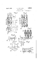
- Figure 1 is a side elevation of our improved radiator hanger in place on a wall and with a radiator indicated in dotted lines;
- Fig.2 is a sectlon taken on the line 2-2 of Fig. 1;
- Fig. 3 1s a horizontal section taken on the line 3-3 of Fig. 1;
- Fig. 4 is a plan view of the bracket arm;
- Fig. 5 is a perspective viewof the radia-, tor engaging and supporting plate;
- FIG. 7 is a perspective view of the plate for attachment to the wall;
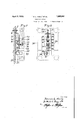
- FIG. 7 is a side elevation showing. the arrangement of thejparts for hanging a radiator of the single column or wall type and with the position of the radiae tor-indicated in dotted lines and
- FigyS is a front elevation of thearrangement shown in F ig.; 7.
- V a We provide a wall engaging plate 9 adapted to besecured by a suitable anchor bolt 10 upon a wall 1 1, the bolt, 10 being'inserted through a hole 12, shown in Figure 6. Upon its lower edge the plate 9 has a flange 13 projecting horizontally away from the wall and formed with an opening 14 to receive and support asuspension bolt'15.
- a tooth 9a projects from the back of the plate 9 to prevent tilting on the wall.
- a bracket arm .17 Supported by a nut '16 on the lower end of the bolt-15 is a bracket arm .17, adapted toproject between thesections of the radiator 18.
- the arm 17 has a sleeve portion 19 130 receive the bolt 15 and a flat bearing surface 20 for engagingthe wall 11.
- depressions21 and 22 In the upper surface of :the arm 17 is formed depressions21 and 22 in which a radiatorengaging pate 23 may be supported as hereinafter described.
- This plate” 23 is preferably made otheavy sheet metal and has openings 24, 25 and 26 disposed along its normally'vertical centerline. Lugs 27 project from onelend of the, plate 23landa slot 28" is formed between the lugs 27t0 receive a bolt 29.
- bolt 29" is provided tosecure the plate 23 to the radiatorasin Figs. land 2,'wh-ere' it is shown in the space between columns and on the outer surface of the columns nearestthe wall.
- the e openings 24 and 25 in the plate 23 are designed 'to selectively receive thebracket arm 17 and. d to engage thesame'in thedepression 21 .in
- the weight of the radiator may be placed on.
- the hanger and the retaining bolt 29 removed, if desired, by loosening the nut on its inner end.
- the spacing of openings 1841. from the inner surface on the radiators of different widths does not vary, it will be evident that the plate 23, when secured in said opening, is uniformly spaced from the wall irrespective of'the size or number of columns of the radiator.
- the lugs 27 project between sections to properly center the plate 23 and insure the engagement adjacent sections.
- the elongated opening 14 permits adjustment of the position of "the bracket arm 17 to register with the s ace between sections where the openings 2 and '25 are located. Adjustments (oi the height .of .the radiator upon the wall are provided for in the nut 16 and openings 24 and into which the arm 17 may be selectively-inserted.
- the bracket arm 17 may be :aused to engage the plate 23 in the opening 25.
- the depression 22 in the arm 17 is employed to retain (the plate 23 at the proper distance from the wall 111 the arrangement of .thehanger shown in Figs. .7 and .8, the spaeing memb r .32 bein further employed for [this .urpose. It wil thus be seen that in this ,a ternate arrangement of our invention the plate 23 becomes a suspension member whereas in the arrangement shown in Figs. 1 and 2 .it-is .under oom .ression by theapplication of the weight .to i s upper edge.
- a radiator hanger a wall engaging member, an arm Suspended firom said memher and arranged to project between sections of a radiator for supporting the same and a plate adapted rto be held engagement with the tubes of a radiator in substantial y parallel relation to the wall, said plate .being runs/aged to span the space between sections of both edges 80 with of the radiator and to engage said sections to support the radiator and being formed with an opening to receive said arm, said arm being insertable in said opening to support the plate and radiator.
- a radiator hanger a wall engaging member, a bracket arm suspended from said member and arranged to project between sections of a radiator for supporting the same, a plate insertable between the tubes of a mediator in substantially parallel relation to the Wall, said plate having laterally projecting'portions for engaging the upper part .of .at least two adjacent sections of the radiator and being formed with an opening to reflexive said arm, said arm being .inseltable in'said opening to support the plate-and radiator andn projection onsaid plate to main- .tain the same in properly centered relation :to the radiator sections.
- a radiator support comprising .a .bracket,.a ,bolt supported thereby, a hanger .member comprising a sleeve having .a vertically disposed web projecting outwardly therefrom, the sleeve being .slidabl on the bolt, and .the outer end of the web @having an .upwardly projecting pin, an adjusting nut-on the .bolt, under the-sleeve, and a plate adapted .to .fit between the tubes of .a radiator anddetachably engaging'the pin.
Landscapes
- Engineering & Computer Science (AREA)
- Physics & Mathematics (AREA)
- Thermal Sciences (AREA)
- Chemical & Material Sciences (AREA)
- Combustion & Propulsion (AREA)
- Mechanical Engineering (AREA)
- General Engineering & Computer Science (AREA)
- Supports For Pipes And Cables (AREA)
Description
April 5, 1932. .0. L. HEALY ET AL RADIATOR HANGER Filed Oct. 22, 1928 &
Dennis/Alisa) attained? 2 Sheets-Sheet l gwuewlioz.
. Q eMZtCPu/ Z April 5, 1932. D. 1.. HEALY ET AL RADIATOR HANGER 2 Sheets-Sheet 2 Filed Oct. 22, 1928 J r I l I I I I l l I I 1 I I I ILH Patented Apr. 5,1932 4 l DENNIS L. nanny-Arman WITT c.aurr, qan,; or sr. rnun-nrnnnsora RAIi A OBI HANGER o a d Application fi lc' d 'oct ober 22, 1928, semi No. 314,282.
This inventionrelates to radiator hangers} forsupporting radiators of the m'odern type whichvary in width between wide limits.
It is our object to provide a hanger adapt-' ed to support any of the modern radiators-of the various sizes in common use and thereby make it unnecessary fora heating contractor tokeep on hand more than'o-ne type and slze ot'hanger. More particularly it is. our object to provide'airadiator hanger with means for engaging'a partof such radiatorswhich isnot variously located in .the radiators of difierent sizes and at the same timeto provide an unusually strong and secure device de signed to facilitate the adjustments necessary to properly position the radiator underthe conditions met in practice.
In the accompanying drawings,Figure 1 is a side elevation of our improved radiator hanger in place on a wall and with a radiator indicated in dotted lines; Fig.2 is a sectlon taken on the line 2-2 of Fig. 1; Fig. 3 1s a horizontal section taken on the line 3-3 of Fig. 1; Fig. 4 is a plan view of the bracket arm; Fig. 5 is a perspective viewof the radia-, tor engaging and supporting plate; Fig. 6
- is a perspective view of the plate for attachment to the wall; Fig. 7 is a side elevation showing. the arrangement of thejparts for hanging a radiator of the single column or wall type and with the position of the radiae tor-indicated in dotted lines andFigyS is a front elevation of thearrangement shown in F ig.; 7. V a We provide a wall engaging plate 9 adapted to besecured by a suitable anchor bolt 10 upon a wall 1 1, the bolt, 10 being'inserted through a hole 12, shown in Figure 6. Upon its lower edge the plate 9 has a flange 13 projecting horizontally away from the wall and formed with an opening 14 to receive and support asuspension bolt'15. A tooth 9a projects from the back of the plate 9 to prevent tilting on the wall. Supported by a nut ' 16 on the lower end of the bolt-15 is a bracket arm .17, adapted toproject between thesections of the radiator 18. The arm 17 has a sleeve portion 19 130 receive the bolt 15 and a flat bearing surface 20 for engagingthe wall 11. In the upper surface of :the arm 17 is formed depressions21 and 22 in which a radiatorengaging pate 23 may be supported as hereinafter described. This plate" 23 is preferably made otheavy sheet metal and has openings 24, 25 and 26 disposed along its normally'vertical centerline. Lugs 27 project from onelend of the, plate 23landa slot 28" is formed between the lugs 27t0 receive a bolt 29. The
saldarm. Tofacilitate securing the plate 23 to the radiator in this position, a tapered head may be placed inengagement withtheradiator between sections and anut on theend of the bolt may be tightened to retainthe i plate. To hold the lower portionof the rad atorin proper spacedirelation to the wall we prefer toemploy a spacer 32-like that described andclaimed in the copending applica-.
'tion ,ofne Witt YCLRHfi, 2d,- filed June 30, I
1928; Serial Number 289,380; Parallel gripping members 133 of the Spacer-32 are arl ranged to be clamped in convenient position u e of the radiator tubes by means of 5 a bolt 34 (see Figs. 1 and 3) I I f .In use, before the radiator 18 is hung upon the wall, the plate 23 may be secured inplace between the columns by meansof the bolt 29.
and head 31', said bolt extending in the slot 28. 'To hang aradiatorfla wall engaging member 9 is secured upon the wall 11 by the anchor bolt 10 in the usual manner, the tooth "962' being embedded in the wall to prevent tilting of the flange 13 out of its substantial-v ly'horizontal position. With the spacer member 32 securedtothe lower portion of the radiator "the latter is raised and the arm 17' caused to pass between sections and through the opening 24 or 25 inthe plate :23. Now
the weight of the radiator may be placed on.
the hanger and the retaining bolt 29 removed, if desired, by loosening the nut on its inner end. As the spacing of openings 1841. from the inner surface on the radiators of different widths does not vary, it will be evident that the plate 23, when secured in said opening, is uniformly spaced from the wall irrespective of'the size or number of columns of the radiator. The lugs 27 project between sections to properly center the plate 23 and insure the engagement adjacent sections. The elongated opening 14 permits adjustment of the position of "the bracket arm 17 to register with the s ace between sections where the openings 2 and '25 are located. Adjustments (oi the height .of .the radiator upon the wall are provided for in the nut 16 and openings 24 and into which the arm 17 may be selectively-inserted.
In the arrangement of our hanger, shown in Figs. .7 and 8, we have provided for the hanging ore-radiator ofthe singlecolumn or wall type rwhich is without openings .oorresp nding to the openings 18a, (Fig 1.). With .a single column radiator the wall engaging member 9 and bracket arm 17 are secured .upon the wall as above described .but the plate 23 is inverted, :as clearly shown .in Fig. 8, and secured upon the surface of the radiator adjacent to the wall. ,To secure the plate 23 upon the radiator a bolt .36 is insorted through the opening 26 in the plate 23.836. :a headBT, having a hore .to {receive the bolt 36, is placed in engagement with the radiator in one of the vertical openings 35a, Fig. 8. By tightening a nut :38a1pon .tho1in her and of the bolt .36, it will .he understood that the plate 23 may he clamped at any desired height upon the inner surface .of the radiator.
With the .plate .23 in this positi n the bracket arm 17 may be :aused to engage the plate 23 in the opening 25. The depression 22 in the arm 17 is employed to retain (the plate 23 at the proper distance from the wall 111 the arrangement of .thehanger shown in Figs. .7 and .8, the spaeing memb r .32 bein further employed for [this .urpose. It wil thus be seen that in this ,a ternate arrangement of our invention the plate 23 becomes a suspension member whereas in the arrangement shown in Figs. 1 and 2 .it-is .under oom .ression by theapplication of the weight .to i s upper edge.
Having described our invention what we claim as new and desire to protect .by Letters Patentis:
L In a radiator hanger a wall engaging member, an arm Suspended firom said memher and arranged to project between sections of a radiator for supporting the same and a plate adapted rto be held engagement with the tubes of a radiator in substantial y parallel relation to the wall, said plate .being runs/aged to span the space between sections of both edges 80 with of the radiator and to engage said sections to support the radiator and being formed with an opening to receive said arm, said arm being insertable in said opening to support the plate and radiator.
2. In a radiator hanger a wall engaging member, a bracket arm suspended from said member and arranged to project between sections of a radiator for supporting the same, a plate insertable between the tubes of a mediator in substantially parallel relation to the Wall, said plate having laterally projecting'portions for engaging the upper part .of .at least two adjacent sections of the radiator and being formed with an opening to reflexive said arm, said arm being .inseltable in'said opening to support the plate-and radiator andn projection onsaid plate to main- .tain the same in properly centered relation :to the radiator sections.
.3. A radiator support comprising .a .bracket,.a ,bolt supported thereby, a hanger .member comprising a sleeve having .a vertically disposed web projecting outwardly therefrom, the sleeve being .slidabl on the bolt, and .the outer end of the web @having an .upwardly projecting pin, an adjusting nut-on the .bolt, under the-sleeve, and a plate adapted .to .fit between the tubes of .a radiator anddetachably engaging'the pin.
In testimony whereof, we vhave hereunto signed our names to this specification.
DENNIS L. I-IEALY.
DE WITT .C. RUFF, 21).
up and down
Priority Applications (1)
| Application Number | Priority Date | Filing Date | Title |
|---|---|---|---|
| US314282A US1852841A (en) | 1928-10-22 | 1928-10-22 | Radiator hanger |
Applications Claiming Priority (1)
| Application Number | Priority Date | Filing Date | Title |
|---|---|---|---|
| US314282A US1852841A (en) | 1928-10-22 | 1928-10-22 | Radiator hanger |
Publications (1)
| Publication Number | Publication Date |
|---|---|
| US1852841A true US1852841A (en) | 1932-04-05 |
Family
ID=23219338
Family Applications (1)
| Application Number | Title | Priority Date | Filing Date |
|---|---|---|---|
| US314282A Expired - Lifetime US1852841A (en) | 1928-10-22 | 1928-10-22 | Radiator hanger |
Country Status (1)
| Country | Link |
|---|---|
| US (1) | US1852841A (en) |
Cited By (2)
| Publication number | Priority date | Publication date | Assignee | Title |
|---|---|---|---|---|
| US2595308A (en) * | 1948-03-03 | 1952-05-06 | Modine Mfg Co | Gas-to-gas heat exchanger |
| US20160084284A1 (en) * | 2013-04-17 | 2016-03-24 | Hbn Agencies | System for Mounting Heating Panels on to Wall Without Drilling Holes on the Wall |
-
1928
- 1928-10-22 US US314282A patent/US1852841A/en not_active Expired - Lifetime
Cited By (3)
| Publication number | Priority date | Publication date | Assignee | Title |
|---|---|---|---|---|
| US2595308A (en) * | 1948-03-03 | 1952-05-06 | Modine Mfg Co | Gas-to-gas heat exchanger |
| US20160084284A1 (en) * | 2013-04-17 | 2016-03-24 | Hbn Agencies | System for Mounting Heating Panels on to Wall Without Drilling Holes on the Wall |
| US9732779B2 (en) * | 2013-04-17 | 2017-08-15 | Hbn Agencies | System for mounting heating panels on to wall without drilling holes on the wall |
Similar Documents
| Publication | Publication Date | Title |
|---|---|---|
| US3603637A (en) | Adjustable arm rest for automobiles | |
| US2522901A (en) | Adjustable picture hanger | |
| US1474660A (en) | Form support | |
| US3198343A (en) | Storage rack | |
| US1852841A (en) | Radiator hanger | |
| US1852650A (en) | Support for flowerpots and the like | |
| US3062945A (en) | Electric heater with plate-clamping reflector | |
| US1786038A (en) | Apparatus for map display | |
| US2903712A (en) | Fixture carrier construction | |
| US2578993A (en) | Wall bracket for radiators | |
| US2546359A (en) | Radiator bracket | |
| US2898064A (en) | Picture hanger device | |
| US1879519A (en) | Radiator hanger | |
| US1878187A (en) | Radiator hanger | |
| US1861599A (en) | Holder for sign characters | |
| US2111918A (en) | Wall hanger for radiators | |
| US2939669A (en) | Hanger assembly for lighting fixtures | |
| US2017710A (en) | Tub bracket | |
| US1887031A (en) | Radiator supporting hanger | |
| US1802939A (en) | Sign | |
| US1505608A (en) | License-plate holder | |
| US2043041A (en) | Bicycle mudguard clamp | |
| US1682486A (en) | Radiator hanger | |
| US1005499A (en) | Hanger for license-plates. | |
| US2053987A (en) | Radiator supporting device |