US1852829A - Dynamo electric machine - Google Patents
Dynamo electric machine Download PDFInfo
- Publication number
- US1852829A US1852829A US438857A US43885730A US1852829A US 1852829 A US1852829 A US 1852829A US 438857 A US438857 A US 438857A US 43885730 A US43885730 A US 43885730A US 1852829 A US1852829 A US 1852829A
- Authority
- US
- United States
- Prior art keywords
- core structure
- shell
- electric machine
- dynamo
- dynamo electric
- Prior art date
- Legal status (The legal status is an assumption and is not a legal conclusion. Google has not performed a legal analysis and makes no representation as to the accuracy of the status listed.)
- Expired - Lifetime
Links
- 239000007859 condensation product Substances 0.000 description 4
- ISWSIDIOOBJBQZ-UHFFFAOYSA-N phenol group Chemical group C1(=CC=CC=C1)O ISWSIDIOOBJBQZ-UHFFFAOYSA-N 0.000 description 4
- 239000000463 material Substances 0.000 description 3
- 239000002184 metal Substances 0.000 description 3
- 239000007787 solid Substances 0.000 description 3
- 239000011248 coating agent Substances 0.000 description 2
- 238000000576 coating method Methods 0.000 description 2
- 229910000831 Steel Inorganic materials 0.000 description 1
- 238000004519 manufacturing process Methods 0.000 description 1
- 238000012986 modification Methods 0.000 description 1
- 230000004048 modification Effects 0.000 description 1
- 239000010959 steel Substances 0.000 description 1
Images
Classifications
-
- H—ELECTRICITY
- H02—GENERATION; CONVERSION OR DISTRIBUTION OF ELECTRIC POWER
- H02K—DYNAMO-ELECTRIC MACHINES
- H02K1/00—Details of the magnetic circuit
- H02K1/06—Details of the magnetic circuit characterised by the shape, form or construction
- H02K1/12—Stationary parts of the magnetic circuit
- H02K1/18—Means for mounting or fastening magnetic stationary parts on to, or to, the stator structures
- H02K1/185—Means for mounting or fastening magnetic stationary parts on to, or to, the stator structures to outer stators
Definitions
- My invention relates to dynamo-elcctri'c machines ot small size of the type ineluding a laminated core structure which is secured in a shell.
- the stationary member constitutes a solid mass which produces a clear ringing note when struck as compared with a dull clatteringr sound in a stationary memv ber in which the shell is not united with the core structure, and I have found that /this characteristic di'tfcrence'gives a clear 35,/ indication as'ito Whether or not the stationary member will make the dynamo-electric machine noisy in operation.
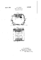
- Fig. lg is a side elevation of a small dynainoclectric machine embodying my invention'
- Fig. 2 is al longitudinal section of the stationary member of the machine.
- a small dymimo-electric machine including a-slotted core structure 10 havingwindings. 11i arranged thereon.
- This core structure is supported in a thin cylindrical steel shell 12 which closely tits the outer periphery of thev core structure and has its edges folded inwardly as indicatedA at 13* ⁇ so as to securely clamp.
- the rotatable mem-ber 14 of the machine includes a shaft which is supported in bearings 15 in the end-heads 1G. The end-heads are secured to the shell .12 by bolts 17 which secure the entire structure together.
- a layer of material such as a phenolic condensation product indicated at 18, so that when the shell and core structure are secured together that the layer of material solidiies and unites the core structure 10 and the shell 12, or so completely ills the space between them that the shell and the core structure constitute a solid mass.
- the coating 1S may be applied after the shell and core structure are assembled by ditecting it into the space between them under pressure.
- a stationary member for dynamo-electric machines including a. laminated core structure, a thin metal shell secured about said core structure, and means including a layer of phenolic condensation product entirely filling the space between said core structure and said shell for preventing their vibrating Withl respect to each other.
- a stationary member for dynamo-electric machines including a laminated core structure, means including a thin metal shell surrounding the entire periphery of said core structure for supporting the same, and a thin hardened layer of phenolic condensation product between said core structure and said shell and conforming thereto for preventing vibration of said shell and said core structure With. respect to each other.
- a stationary member for dynamo-electric machines including an annular laminated core structure, a thin metal shell closely fitting theperiphery of said core structure, said shell havingthe edges thereof turned inwardly to secure said core structure between them, and a thin rigid'layer of a phenolic condensation product between said core structure and said shell, said layer of material being united to said shell and said core structure to prevent their vibrating with respect to each other.
Landscapes
- Engineering & Computer Science (AREA)
- Power Engineering (AREA)
- Iron Core Of Rotating Electric Machines (AREA)
Description
April'S, 1932. A. F. WELCH DYNAMO ELECTRIC MACHINE Filed March 25, 1930 ,a Figa.
e bww Il@ 1, f@ .o Fw am m gw Patented Apr. 5, 1932 UNITED STATES PATENT OFFICE .ALFRED F. WELCH, OF FORT WAYNE, INDIANA, ASSIGNOR T GENERAL ELECTRIC COM- PANY, A CORPORATION 0F NEW YORK DYNAMO ELECTRIC MACHINE Application filed vMarch 25, 1930. Serial No. 438,857. h
My invention relates to dynamo-elcctri'c machines ot small size of the type ineluding a laminated core structure which is secured in a shell.
In making small stationaryv members for dynamo-electric machines of this type heretofore, it Was found that a large percentage of the stationary members mamltactured have had to be rejected after the machines were completed because of their being noisy in opera-tion. Every possible precaution was taken in the n'ianufacture of these machines' to obtain quiet operation such as making the parts accurately to the required dimensions,
making the rotor exactly concentric with recore structure having a. shell secured about .the same and united therewith to .prevent their vibrating With respect to each other. In this way the stationary member constitutes a solid mass which produces a clear ringing note when struck as compared with a dull clatteringr sound in a stationary memv ber in which the shell is not united with the core structure, and I have found that /this characteristic di'tfcrence'gives a clear 35,/ indication as'ito Whether or not the stationary member will make the dynamo-electric machine noisy in operation.
My invention will be more fullyT set forth in the followingr description referring to 40 the accompanying drawings, and the features of novelty which characterize my invention will he pointed out with particularity in the claims annexed to and forming a part of this specification.
.3 In the drawings Fig. lgis a side elevation of a small dynainoclectric machine embodying my invention', and Fig. 2 is al longitudinal section of the stationary member of the machine.
0 Referring to the dran/"ings, I have shown my invention in connection with a small dymimo-electric machine including a-slotted core structure 10 havingwindings. 11i arranged thereon. This core structure is supported in a thin cylindrical steel shell 12 which closely tits the outer periphery of thev core structure and has its edges folded inwardly as indicatedA at 13*` so as to securely clamp. the core structure 1() between the opposing intnrned edges. of the shell. The rotatable mem-ber 14 of the machine includes a shaft which is supported in bearings 15 in the end-heads 1G. The end-heads are secured to the shell .12 by bolts 17 which secure the entire structure together.
In manufacturing these stationary mem# bers it has been found that vibration of the shell 12 with respect to the annular core structure l0 causes the machine to be noisy in operation. vWhen the annular core structure and the shell are not united they do vibrate with respect to each other and this may readily be detected by striking the shell as it then gives a dull clattering sound. In accordance with my invention, therefore, I unite the shell 12 and the annular core structure 10 so that they constitute a solid mass which gives a clear musical note when struck. I prefer to unite the annular core structure and the shell by coating one or the other with a layer of material such as a phenolic condensation product indicated at 18, so that when the shell and core structure are secured together that the layer of material solidiies and unites the core structure 10 and the shell 12, or so completely ills the space between them that the shell and the core structure constitute a solid mass. It will be understood, of course, that if desired the coating 1S may be applied after the shell and core structure are assembled by ditecting it into the space between them under pressure.
All though I have shown my invention in connection with a dynamo-electric machine ot a particular type, I do not desire to be limited thereto, and I intend in the appended claims to cover all modifications which do not depart from the spirit and scope of my invention.
What I claim as new and desire to secure by Letters `Patent of the United States is:
1. A stationary member for dynamo-electric machines including a. laminated core structure, a thin metal shell secured about said core structure, and means including a layer of phenolic condensation product entirely filling the space between said core structure and said shell for preventing their vibrating Withl respect to each other.
2. A stationary member for dynamo-electric machines including a laminated core structure, means including a thin metal shell surrounding the entire periphery of said core structure for supporting the same, and a thin hardened layer of phenolic condensation product between said core structure and said shell and conforming thereto for preventing vibration of said shell and said core structure With. respect to each other. v
3. A stationary member for dynamo-electric machines including an annular laminated core structure, a thin metal shell closely fitting theperiphery of said core structure, said shell havingthe edges thereof turned inwardly to secure said core structure between them, and a thin rigid'layer of a phenolic condensation product between said core structure and said shell, said layer of material being united to said shell and said core structure to prevent their vibrating with respect to each other.
In Witness whereof, I have hereunto set my hand this 21st day of March, 1930.
ALFRED F. WELCH.
Priority Applications (1)
| Application Number | Priority Date | Filing Date | Title |
|---|---|---|---|
| US438857A US1852829A (en) | 1930-03-25 | 1930-03-25 | Dynamo electric machine |
Applications Claiming Priority (1)
| Application Number | Priority Date | Filing Date | Title |
|---|---|---|---|
| US438857A US1852829A (en) | 1930-03-25 | 1930-03-25 | Dynamo electric machine |
Publications (1)
| Publication Number | Publication Date |
|---|---|
| US1852829A true US1852829A (en) | 1932-04-05 |
Family
ID=23742309
Family Applications (1)
| Application Number | Title | Priority Date | Filing Date |
|---|---|---|---|
| US438857A Expired - Lifetime US1852829A (en) | 1930-03-25 | 1930-03-25 | Dynamo electric machine |
Country Status (1)
| Country | Link |
|---|---|
| US (1) | US1852829A (en) |
Cited By (5)
| Publication number | Priority date | Publication date | Assignee | Title |
|---|---|---|---|---|
| US2582005A (en) * | 1948-10-27 | 1952-01-08 | Gen Motors Corp | Stator and method of making same |
| US2668925A (en) * | 1949-04-05 | 1954-02-09 | Kearfott Company Inc | Electric machine construction |
| US2941098A (en) * | 1958-08-04 | 1960-06-14 | Thompson Tool And Mfg Co | Portable tool assembly |
| US2953699A (en) * | 1958-02-07 | 1960-09-20 | Us Electrical Motors Inc | Stator structures for dynamo-electric machines |
| WO1987003147A1 (en) * | 1985-11-06 | 1987-05-21 | Robert Bosch Gmbh | Device for fixing the stator of a three-phase current alternator |
-
1930
- 1930-03-25 US US438857A patent/US1852829A/en not_active Expired - Lifetime
Cited By (6)
| Publication number | Priority date | Publication date | Assignee | Title |
|---|---|---|---|---|
| US2582005A (en) * | 1948-10-27 | 1952-01-08 | Gen Motors Corp | Stator and method of making same |
| US2668925A (en) * | 1949-04-05 | 1954-02-09 | Kearfott Company Inc | Electric machine construction |
| US2953699A (en) * | 1958-02-07 | 1960-09-20 | Us Electrical Motors Inc | Stator structures for dynamo-electric machines |
| US2941098A (en) * | 1958-08-04 | 1960-06-14 | Thompson Tool And Mfg Co | Portable tool assembly |
| WO1987003147A1 (en) * | 1985-11-06 | 1987-05-21 | Robert Bosch Gmbh | Device for fixing the stator of a three-phase current alternator |
| US4894574A (en) * | 1985-11-06 | 1990-01-16 | Robert Bosch Gmbh | Stator support for electric machine |
Similar Documents
| Publication | Publication Date | Title |
|---|---|---|
| US2554226A (en) | Dynamoelectric machine core mounting | |
| US3260875A (en) | Dynamoelectric machine core and method of making same | |
| US2303893A (en) | Dynamo-electric machine | |
| US1852829A (en) | Dynamo electric machine | |
| US2685658A (en) | Dynamoelectric machine | |
| US2199141A (en) | Dynamoelectric machine | |
| KR910007211A (en) | Arrangements for fixing the winding ends of the stator windings in a dynamoelectric machine | |
| US3906264A (en) | Rotor vibration suppressing apparatus for miniature electric motors | |
| US1808572A (en) | Rotor for dynamo electric machines | |
| US2058362A (en) | Laminated core for electrical apparatus | |
| US493337A (en) | Armature for dynamo-electric machines | |
| US1401708A (en) | Commutator-cylinder | |
| US2083395A (en) | Method of making cores for electrical apparatus | |
| US1031316A (en) | Dynamo-electric machine. | |
| US2249834A (en) | Balance-ring combination | |
| US2323035A (en) | Synchronous motor | |
| US784032A (en) | Laminated core for dynamo-electric machines. | |
| US582481A (en) | Fastening means for core-plates of electrical machines | |
| US2027136A (en) | Dynamo-electric machine | |
| US2235807A (en) | Electric motor frame construction | |
| US1158495A (en) | Induction-motor. | |
| US3054005A (en) | Electric motor | |
| US479030A (en) | Armature for electric machines | |
| US2447383A (en) | Rotatable electrical device | |
| US1685742A (en) | Core for electrical apparatus |