US1852801A - Ribbon feed mechanism - Google Patents
Ribbon feed mechanism Download PDFInfo
- Publication number
- US1852801A US1852801A US438553A US43855330A US1852801A US 1852801 A US1852801 A US 1852801A US 438553 A US438553 A US 438553A US 43855330 A US43855330 A US 43855330A US 1852801 A US1852801 A US 1852801A
- Authority
- US
- United States
- Prior art keywords
- ribbon
- feed mechanism
- roll
- gear
- ribbon feed
- Prior art date
- Legal status (The legal status is an assumption and is not a legal conclusion. Google has not performed a legal analysis and makes no representation as to the accuracy of the status listed.)
- Expired - Lifetime
Links
- 230000033001 locomotion Effects 0.000 description 9
- 238000004804 winding Methods 0.000 description 4
- 238000010276 construction Methods 0.000 description 2
- 230000000694 effects Effects 0.000 description 1
- ORQBXQOJMQIAOY-UHFFFAOYSA-N nobelium Chemical compound [No] ORQBXQOJMQIAOY-UHFFFAOYSA-N 0.000 description 1
- 230000003014 reinforcing effect Effects 0.000 description 1
Images

Classifications
-
- B—PERFORMING OPERATIONS; TRANSPORTING
- B65—CONVEYING; PACKING; STORING; HANDLING THIN OR FILAMENTARY MATERIAL
- B65H—HANDLING THIN OR FILAMENTARY MATERIAL, e.g. SHEETS, WEBS, CABLES
- B65H20/00—Advancing webs
- B65H20/24—Advancing webs by looping or like devices
-
- B—PERFORMING OPERATIONS; TRANSPORTING
- B65—CONVEYING; PACKING; STORING; HANDLING THIN OR FILAMENTARY MATERIAL
- B65H—HANDLING THIN OR FILAMENTARY MATERIAL, e.g. SHEETS, WEBS, CABLES
- B65H2301/00—Handling processes for sheets or webs
- B65H2301/40—Type of handling process
- B65H2301/44—Moving, forwarding, guiding material
- B65H2301/449—Features of movement or transforming movement of handled material
- B65H2301/4491—Features of movement or transforming movement of handled material transforming movement from continuous to intermittent or vice versa
-
- B—PERFORMING OPERATIONS; TRANSPORTING
- B65—CONVEYING; PACKING; STORING; HANDLING THIN OR FILAMENTARY MATERIAL
- B65H—HANDLING THIN OR FILAMENTARY MATERIAL, e.g. SHEETS, WEBS, CABLES
- B65H2801/00—Application field
- B65H2801/91—Recording tape manufacture
Definitions
- My said invention relates to improvements in ribbon feed mechanism intended to supply ribbon from a supply spool to intermittently acting ribbon applying means.
- mechanism designed to successively apply such tapes to the out together seams of articles made from unvulcanized rubber sheets and subsequently vulcanized, and is particularly adapted for use in connection-with seam reinforcing means such as disclosed in an application filed by me in the United States Patent Office on the th day of De cember, 1929, Serial Number 415,545, now Patent No. 1,828,997.
- the invention aims to provide ribbon feed mechanism which will be strong and durable in construction and which will permit the ribbon to be conductedto the work with minimum amount of resistance.
- the invention also aims to provide means by which the ribbon will be drawn from a supply roll in successive loops ofpredeter mined length which loops are successively drawn upon for application to the seams.
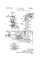
- Figure 1 is a side elevation of my improved feed mechanism with a portion of the table top of the applying machine of my aforesaid ap lication shown in section.
- ig. 2 is a plan View of the drive mechanism for the cable operating drum.
- Fig. 3 is an end elevation.
- Fig. 4 is a section 011 line 4-4 of Fig. 2.
- Fig. dis a section on line 5-5 of Fig. 1.
- Figs. 6 and 7 are detail views in side elevation and plan respectively of a modified form of drive. 7
- the numeral 6 designates the table 7 top of the ribbon or tape applying machine 1930. Serial No. 438,553.
- a pivoted pawl-like device 1010 acting in conjunction with the guide roll lOlserves to prevent any retrograde movement of the ribbon under the action of the floating roller 99 as hereinafter described.
- the roller is drawn downwardly during the time the ribbon applying means is at rest or is inactive thereby forming a depending loop, the extent of movement of the roller being such that exactly the amount of ribbon required for a single article or applying operation, is formed into such loop.
- the ribbon is drawn upon for application .with the article the floating roller is raised'in such a manner as to relieve the loop of all resistance and the tape is thereby fed to thework from a slack loop.
- I connect to the slide 100 thereof the one end of a cable or like flexible element 102 which passes upward to and over an idle pulley 103 journaled at the top of the standard, from which idle pulley the cable descends through opening fia to and around idle-pulley 104: journaled in bearings carried by the standard. From pulley 104, the cablepasses to the winding drum 105, preferably of pulley form, to which'the end of the cable is attached.
- This winding pulley 105 is designed to oscillate, and to have imparted thereto an alternating rotary movement, rotating first in one direction through nearly a complete rotation and then in the reverse direction, and its periphery is of such extent as, in the winding action, to draw sufficiently on the cable to raise the slide the required height.
- Said drum 105' is fast on stub shaft 106 journaled in a bearing bracket Also fast on this shaft is a spur gear 108 which meshes with a spur gear 109 to provide amplified movement from the driving mechanism, said gear 109 being fast on shaft 118.
- Motion is derived from the chain 68 of my aforesaid application which passes around pulley 111 fast on sleeve 110.
- This sleeve passes through a bearing bracket 112 and has secured to its other end the hub of an eccentric member 113, the strap 114 of which is connected by pitman 114a to a pivot pin carried by an car 115 of a gear segment 116 mounted to oscillate on fixed stub shaft 116a.
- the gear segment 116 is oscillated and thereby oscillates gear 117 with which it is in mesh.
- this gear 11'lis fast on shaft 118 to which pinion 109, previously referred to, is secured it will be seen that the oscillating movement of the gear segment will impart corresponding alternating rotary movement to the pulley or drum 105.
- a shaft of the ribbon applying machine carries a crank arm 120 designed to make a complete rotation during the activecycle.
- This 0 crank arm is connected by pitman 121 to the gear (or gear segment), 122 by offset pivot 121a, whereby the rotation of the crank imparts alternating rotary movement to said gear or gear segment which is journaledto rotate about fixed axis 122a.
- Gear member 122 meshes'with a pinion 123 fast on shaft 106a (similar to shaft 106 in the form first described), which shaft carries a winding and unwinding pulley or drum 1 050, to which the 9 slide operating cable 102 of the floating roll 104 is attached.
- V v p v Ribbon feed mechanism for fecdingrib- 5 bon to intermittently operating ribbon applying means, said mechanism comprising a rotatable supply spool, a guide roll adjacent the same, means for preventing rotation thereof in one direction, a'vertical-ly movable contact with the ribbon during rotation of J the guide roll and for permitting descent roll located below said spool and guide roll,-
- Ribbon feed mechanism for intermittently supplying ribbon applying means said mechanism comprising a frictionally retarded supply spool, a ribbon guide roll adjacent the same, a vertically movable'idle' roll located below said spool and guide roll, said ribbon passing from said spool around said movable idle roll and over said guide r011,
Landscapes
- Impression-Transfer Materials And Handling Thereof (AREA)
Description
April 5, 1932. A. E. COLLINS RIBBON FEED MECHANISM Filed March 24. 1930 2 Sheets-Shee n 1 5 m H m I I \1 I I m w 1 w. m H E 9 1 6 O 1 O 1 o 1 o m 1 o.
April 5, 1932.- A. E. COLLINS 8 ,8
RIBBON FEED MECHANISM Filed March 24, 1930 2 Sheets-Sheet 2 q qliligilllIli-ileilllu.
Arfl'hurE. Callins; V
12 /%m WW wag referred to in the aforesaid application which Patented Apr. 5, 1932 UNITED STATES PATENT OFFICE ATE-THUR E. COLLINS, OF CUYAHOGA FALLS, OHIO, ASSIGNOR, BY MESNE ASSIGNMENTS,
TO MILLER RUBBER COMPANY INC., 016 WILMINGTON, DELAWARE, A CORPORATION OF DELAWARE RIBBON FEED MECHANISM Application filed March 24,
My said invention relates to improvements in ribbon feed mechanism intended to supply ribbon from a supply spool to intermittently acting ribbon applying means.
It is designed more especially for supplying ribbon or tape of unvulcanized rubber to. mechanism designed to successively apply such tapes to the out together seams of articles made from unvulcanized rubber sheets and subsequently vulcanized, and is particularly adapted for use in connection-with seam reinforcing means such as disclosed in an application filed by me in the United States Patent Office on the th day of De cember, 1929, Serial Number 415,545, now Patent No. 1,828,997.
The invention aims to provide ribbon feed mechanism which will be strong and durable in construction and which will permit the ribbon to be conductedto the work with minimum amount of resistance.
The invention also aims to provide means by which the ribbon will be drawn from a supply roll in successive loops ofpredeter mined length which loops are successively drawn upon for application to the seams.
With these and other objects in view, the invention includes the novel features of construction and arrangement and combination of parts hereinafter described, the invention being defined by the claims appended hereto. In order that the invention may be more readily understood, reference is made to the accompanying drawings in which: Figure 1 is a side elevation of my improved feed mechanism with a portion of the table top of the applying machine of my aforesaid ap lication shown in section.
ig. 2 is a plan View of the drive mechanism for the cable operating drum.
Fig. 3 is an end elevation.
Fig. 4 is a section 011 line 4-4 of Fig. 2. Fig. dis a section on line 5-5 of Fig. 1. Figs. 6 and 7 are detail views in side elevation and plan respectively of a modified form of drive. 7
Referring byreference characters to these drawings, the numeral 6 designates the table 7 top of the ribbon or tape applying machine 1930. Serial No. 438,553.
to and around a floating idle roller 99 rotat- V ably carried by a slide member 100 vertical.- 1y guided by the standard 96,'from which idle roll the ribbon passes upward to and around the idle guide roller 101 carried by a bracket 96b fast on the standard in the vicinity of the supply spool but on the opposite side of the standard. From thisidle guide roll the ribbon is conducted to the ribbon applying means as disclosedin said application.
A pivoted pawl-like device 1010; acting in conjunction with the guide roll lOlserves to prevent any retrograde movement of the ribbon under the action of the floating roller 99 as hereinafter described.
In such action, the roller is drawn downwardly during the time the ribbon applying means is at rest or is inactive thereby forming a depending loop, the extent of movement of the roller being such that exactly the amount of ribbon required for a single article or applying operation, is formed into such loop. While the ribbon is drawn upon for application .with the article the floating roller is raised'in such a manner as to relieve the loop of all resistance and the tape is thereby fed to thework from a slack loop. In order to effect this vertical rectilinear move ment of the floating roller, I connect to the slide 100 thereof the one end of a cable or like flexible element 102 which passes upward to and over an idle pulley 103 journaled at the top of the standard, from which idle pulley the cable descends through opening fia to and around idle-pulley 104: journaled in bearings carried by the standard. From pulley 104, the cablepasses to the winding drum 105, preferably of pulley form, to which'the end of the cable is attached. This winding pulley 105 is designed to oscillate, and to have imparted thereto an alternating rotary movement, rotating first in one direction through nearly a complete rotation and then in the reverse direction, and its periphery is of such extent as, in the winding action, to draw sufficiently on the cable to raise the slide the required height.
Said drum 105' is fast on stub shaft 106 journaled in a bearing bracket Also fast on this shaft is a spur gear 108 which meshes with a spur gear 109 to provide amplified movement from the driving mechanism, said gear 109 being fast on shaft 118.
Motion is derived from the chain 68 of my aforesaid application which passes around pulley 111 fast on sleeve 110. This sleeve passes through a bearing bracket 112 and has secured to its other end the hub of an eccentric member 113, the strap 114 of which is connected by pitman 114a to a pivot pin carried by an car 115 of a gear segment 116 mounted to oscillate on fixed stub shaft 116a. By this arrangement, the gear segment 116 is oscillated and thereby oscillates gear 117 with which it is in mesh. As this gear 11'lis fast on shaft 118 to which pinion 109, previously referred to, is secured, it will be seen that the oscillating movement of the gear segment will impart corresponding alternating rotary movement to the pulley or drum 105.
Instead of using the transmitting mechanism above described, I may use the modified form shown in Figures 6 and 7 in which a shaft of the ribbon applying machine carries a crank arm 120 designed to make a complete rotation during the activecycle. This 0 crank arm is connected by pitman 121 to the gear (or gear segment), 122 by offset pivot 121a, whereby the rotation of the crank imparts alternating rotary movement to said gear or gear segment which is journaledto rotate about fixed axis 122a. Gear member 122 meshes'with a pinion 123 fast on shaft 106a (similar to shaft 106 in the form first described), which shaft carries a winding and unwinding pulley or drum 1 050, to which the 9 slide operating cable 102 of the floating roll 104 is attached.
Having thus described my invention, what I claim is: V v p v 1. Ribbon feed mechanism for fecdingrib- 5 bon to intermittently operating ribbon applying means, said mechanism comprising a rotatable supply spool, a guide roll adjacent the same, means for preventing rotation thereof in one direction, a'vertical-ly movable contact with the ribbon during rotation of J the guide roll and for permitting descent roll located below said spool and guide roll,-
thereof to Withdraw a loop of ribbon from said supply spool.
V 2. Ribbon feed mechanism for intermittently supplying ribbon applying means said mechanism comprising a frictionally retarded supply spool, a ribbon guide roll adjacent the same, a vertically movable'idle' roll located below said spool and guide roll, said ribbon passing from said spool around said movable idle roll and over said guide r011,
ribbon between said supply roll and said idler roll, gravitationally actuated means for causing said looper roll to withdraw a loop of ribbon from said supply roll, and poweractuated means for retractingsaid looper roll during the feeding of the looped ribbon over said idler roll and in advance of said l'oop.
In testimony whereof, I affix lsigl-iature'.
ARTHUR COLLINS.
Priority Applications (1)
| Application Number | Priority Date | Filing Date | Title |
|---|---|---|---|
| US438553A US1852801A (en) | 1930-03-24 | 1930-03-24 | Ribbon feed mechanism |
Applications Claiming Priority (1)
| Application Number | Priority Date | Filing Date | Title |
|---|---|---|---|
| US438553A US1852801A (en) | 1930-03-24 | 1930-03-24 | Ribbon feed mechanism |
Publications (1)
| Publication Number | Publication Date |
|---|---|
| US1852801A true US1852801A (en) | 1932-04-05 |
Family
ID=23741068
Family Applications (1)
| Application Number | Title | Priority Date | Filing Date |
|---|---|---|---|
| US438553A Expired - Lifetime US1852801A (en) | 1930-03-24 | 1930-03-24 | Ribbon feed mechanism |
Country Status (1)
| Country | Link |
|---|---|
| US (1) | US1852801A (en) |
-
1930
- 1930-03-24 US US438553A patent/US1852801A/en not_active Expired - Lifetime
Similar Documents
| Publication | Publication Date | Title |
|---|---|---|
| US2135668A (en) | Spooling machine | |
| US2986781A (en) | Apparatus for longitudinal feeding and laying of flexible strands | |
| US2383562A (en) | Beam letoff | |
| US1852801A (en) | Ribbon feed mechanism | |
| US2218062A (en) | Plaiter-down folding attachment and method of laying the cloth | |
| US1952209A (en) | Cloth cutting machine | |
| US2605053A (en) | Synchronous follower drive for spooler traverses | |
| US1161284A (en) | Spooling-machine. | |
| GB639915A (en) | Improvements in or relating to stitching machines | |
| US2276479A (en) | Cloth feeding device for unwinding and laying up machines | |
| US2281308A (en) | Mechanism for the manufacture of comfortables, quilts, and the like | |
| US1587639A (en) | Paper-feed device | |
| US1316845A (en) | Giovanni magnasco | |
| US1127551A (en) | Cordage-machine. | |
| US2147856A (en) | Bag manufacture | |
| US3059547A (en) | Side seam sealing mechanism for bag making machines | |
| US2081962A (en) | Cutting machine or the like and drive therefor | |
| US1950913A (en) | Sewing machine | |
| US2246363A (en) | Tension and take-up device | |
| US1499924A (en) | Machine for cutting tubular stock into continuous strips | |
| US1524707A (en) | Pinking and winding machine | |
| US1431052A (en) | Soft-ball machine | |
| US1787208A (en) | Machine for cutting bias fabrics | |
| US594290A (en) | sohwaez | |
| GB794463A (en) | Folding machine for piling fabric in superposed folds preparatory to simultaneous cutting of the various folds according to a pattern |