US1852800A - Vertical tube furnace - Google Patents
Vertical tube furnace Download PDFInfo
- Publication number
- US1852800A US1852800A US480306A US48030630A US1852800A US 1852800 A US1852800 A US 1852800A US 480306 A US480306 A US 480306A US 48030630 A US48030630 A US 48030630A US 1852800 A US1852800 A US 1852800A
- Authority
- US
- United States
- Prior art keywords
- support
- furnace
- articles
- stacked
- motor
- Prior art date
- Legal status (The legal status is an assumption and is not a legal conclusion. Google has not performed a legal analysis and makes no representation as to the accuracy of the status listed.)
- Expired - Lifetime
Links
Images
Classifications
-
- F—MECHANICAL ENGINEERING; LIGHTING; HEATING; WEAPONS; BLASTING
- F27—FURNACES; KILNS; OVENS; RETORTS
- F27D—DETAILS OR ACCESSORIES OF FURNACES, KILNS, OVENS OR RETORTS, IN SO FAR AS THEY ARE OF KINDS OCCURRING IN MORE THAN ONE KIND OF FURNACE
- F27D11/00—Arrangement of elements for electric heating in or on furnaces
- F27D11/02—Ohmic resistance heating
-
- H—ELECTRICITY
- H05—ELECTRIC TECHNIQUES NOT OTHERWISE PROVIDED FOR
- H05B—ELECTRIC HEATING; ELECTRIC LIGHT SOURCES NOT OTHERWISE PROVIDED FOR; CIRCUIT ARRANGEMENTS FOR ELECTRIC LIGHT SOURCES, IN GENERAL
- H05B3/00—Ohmic-resistance heating
- H05B3/62—Heating elements specially adapted for furnaces
- H05B3/64—Heating elements specially adapted for furnaces using ribbon, rod, or wire heater
Definitions
- t a tic es o be heated may be stac ed ar upon the ot er and m ssed in th tack d r la io hrough the tu -nece- Gur invention has particular application to the .”Eurnaces for carrying u a p e mined heatcycle on a plurality of uniformly shaped articles which may be stacked and passed in this stacked relation through the furnace;
- the articles maybe in the formo-f disl s in which case We provide an upright cylindrical heating chamber with meansat the top and bottom for sealing the chamberaround the articles so that a suitable selected atmosphere may be used in the furnace.
- Our invention also comprehends, among other features, means for lowering the stacked articles so as to pass them through the heating chamber and for removing articles from the stack after they have emerged from the furnace, together with a sectional construction for the furnace whereby the heater may be readily accessible for repairs.
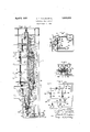
- Fig. 1 is an elevation View partly in vertical-section of an electric furnace embodyingourinvention
- Fig. 2 is a plan View of the mechanism for lowering the articles
- Fig.3 is a fragmentary elevation View of the apparatus shown in Fig. 2
- Fig. 4 is a diagrammatic view showingthe control circuitsfor lowering'the apparatus.
- FIG. 1 of the drawings We have shown our invention in one form as particularly adapted'forcarrying out a predetermined heat cycle on a pluralityof dislrshaped articles '10.
- the heating chamber 11 is tubular in form and is placed in a vertical position with the disksh-apedarticles-to be heat treated stackedupo-n each. other. on a vertically adjustable support 12 'ad acent the lower end of the furnace.
- thestack d.erti sform a con n ous column extending from the support .12 upward through the entire length of the heating chamber and projecting from the top opening.
- the column of stacked articles in the heating chamber itself has been omitted from the drawings.
- the heating chamber is of considerable height its vertical dimension in atypical example being about t is supported on a suitable metallic framework 13.
- a tubular member 18 which in the low temperature region vmay be madeof steel.
- a tubular member 19 made of asuitable heat resisting material such as an alloy of nickel or chromium.
- heat refractory electrical insulating sections or members 20 Surrounding the two members 18 and 19 are heat refractory electrical insulating sections or members 20 which are fitted together to form an insulating support on which is wound a heating resistor 21 formed of ,a suitable heat resisting material such afS-an-alloyof iron, nickel and chromium. Surrounding the heating resistor are layers, as showntwo-layers, of heat refractory bricks 22. Near the lower endof the tubular member 19 a third layer 23 of heatresisting material is provided for increased heat insulation du -t th igher temp ra r a this point, the casing being enlarged accordingly.
- a plurality of lugs 26 are provided on the lower end of the member 19 on which the inner layer of insulation rests. he other two outer layers are supported on a ring 27 which is in turn supported by bolts 28 eX- tending through the horizontal portion 29 of the casing connecting the upper section with the lower larger section.
- the upper portion 17 is a separable removable unit. It will further be observed that the portions of the tubular members 18 and 19 above and below the flange 25 are free to expand and contract, a packing joint 30 being provided to form a gastight seal between the member 18 and the outer casing so that a suitable selected gas such as hydrogen may be admitted to the outer casing which is gastight, there being suitable sufficient openings, for example at the joints between the inner sections defining the heating chamber, to give the gas access into the heating chai ber.
- a suitable selected gas such as hydrogen
- the central section 31 of the furnace is somewhat different in construction in order to adapt it for the still hi her temperatures, the maximum temperature of operation being reached in this section.
- the heating chamber is defined by a tubular member 32 made of suitable heatrefractory electrical insulating material such as Alundum or bonded aluminum oxide on which the heating resistor 33, preferably made of molybdenum, is wound.
- This inner tube and heating resistor is in turn surrounded by a second Alundum tube 84 around which is packed a suitable powdered heat refractory material 35 such as powdered aluminum oxide, the outer tube 34 and powdered insulating material being supported at the lower end on I suitable heat insulating bricks 36.
- Two outer layers 37 and 38 of heat insulating bricks are also provided.
- the layers of heat insulating bricks are supported on the outer casing of this central section by means of an internal flange 39 at the bottom of the section which engages with the outer layer of bricks, a metallic ring 40 secured by brackets (not shown) to the outer casing and forming a support for the next inner layer, and a second metallic ring 41 secured in the second layer of bricks and supporting the innermost layer of bricks 36.
- This central section also is removable as a unit.
- the inner tubular member 32 is supported by the inner tubular member 44 of the lowermost section.
- the construction of the lowermost section V 42 is very similar to the construction of the upper section 17 and differs mainly in the arrangement for supporting the varlous parts. As shown this section is somewhat longer, however, than the uppermost section since a longer time may be required to cool the articles than to heat them. The required cooling time, however, will obviously vary with character of the material and the required final temperature. The length of the cooling section can be designed accordingly.
- the lowermost section 42 comprises an inner steel tubular member 43 at the lower end defining the heating chamber and an upper tubular member 44 made of a heat resisting alloy. Sectional heat refractory members 45 are placed around these metallic tubes and form supports for the heating resistors 46 and 47 by means of which the temperature gradient in this cooling end of the furnace is regulated.
- the casing in this lower section is formed in steps gradually decreas ing in diameter toward the lower end in such manner as to give the desired rate of heat dissipation and hence desired temperature distribution.
- Shoulders 48, 49, 50 and 51 are thus provided which are utilized as sup ports for the layers of heat insulating brick and the various parts.
- A. gastight packing joint 52 is provided around the member 43 at the lower end, whereby the members 43 and 44 are free to expand downward.
- a suitable gas such as hydrogen is admitted into the interior of the gastight outer casing through suitable conduits 53, 53a and 535 located at intervals along the length of the furnace. These conduits extend through the outer layers of heat insulating brick into the relatively narrow space 54 provided between the heating resistor and the surrounding insulating bricks. It will be noted thatthis same space 54 is provided in all the var ous sections so that the gas has free access to the heating resistors to prevent oxidation of these parts as well as other parts in the interior of the casing. leis previously. noted, the gas has access also through the cracks and crevices between the various sections or through openings for this purpo e, if necessary, into the interior of the heating chamber so as to protect the material being heated.
- Electrical insulated terminals for the heating resistors are brought out through the casing at convenient points in each section.
- the upper resistor 21 is provided with terminals 55 and 56, and the central heating resistor 83 with the terminals 57 and 5%.
- the heating resistor in the lower section 42 of the furnace is divided into two sections having respectively terminals 59. 60 and 61, 62. In the operation of the furnace these various sections of the heating resistor are separately controlled so as to maintain each zone of the furnace as defined by the heating resistors at some predetermined temperature.
- thermocouples are subject to rapid deterioration in the atmosphere encountered and consequently they are inserted onlyoccasionally to checkthetemperature against a suitable optical pyrometer.
- the voltage of the heatinglunit in this high temperature zone is automatically regulated and the input to the heating unit is varied, when necessary, by a hand regulatorto maintain the desired temperature.
- a hand regulator to maintain the desired temperature.
- this hand regulator which may be of any suitable type operatingito vary the voltage or the heating resistor itself. Since the disks have a definite weight and travel through the furnace at a definite speed, this hand control affords a practical way of maintaining a given temperature within the desired limits.
- thermocouples were maintained in operative relation with the furnace chamber and they were connected with theheating resistor through suitable control means (not shown) such for example as disclosed in the Collins Patent 1,89'1,'996,dated Sept-27, 1921, so as to maintain suitable temperatures in their respective sections. In this manner a gradually decreasing temperature from the central section towardeachend ismaintained.
- suitable control means such for example as disclosed in the Collins Patent 1,89'1,'996,dated Sept-27, 1921
- thestack of disks 10 being heat treated are supported on the member 12 adjacent the lower end of the furnace.
- This member 12 is carried on'a vertical screw 70, which in turn is supported :on the 'Worm gear 71 provided with a central tapped opening for the screw.
- worm gear 71 Cooperating with the worm '72 is the worm gear 71 by means of which the worm gear may be rotated to raise or lower the support 12.
- a worm gear For turning the worm gear to lower the support 12 with its load of stacked articles, a
- main driving motor 73 is'provided which, as shown in Fig. 2, is connected to the worm 72 through a spur reducing gear 74, shaft '75, a worm reducing gear 76 and an electromagnetically operated clutch .77 suitably biased to thedisengaged position.
- Asecond or auxiliarydriven motor 78 is provided forrapidly turning the worm gear 71 without load so as to raise the support 12. This motor is connected to the shaft of the worm 7 2 through the gearing 79 andanelectromagneticclutch 80, also suitably biased to the disengaged position.
- Additional supporting means comprising a clamping device 81 is also provided for the stacked articles. 'above the support 12. Its function is to hold This device is situated the stacked articles .so that the support 12 :may be lowered somewhat to release the articles 82 between it and the clamping device whereby these articlesmay be removed. The support is then raised "rapidly "by .means of the high speed motor 78, the clutch 80 then be ngengaged with the clutch .7 7 disengaged,
- the clamping device 81 is operated by a suitable motor shown as a hydraulic motor 83. This motor is controlled by clamping :and releasing valves which are operated by magnets 84 and 85, Fig. 4.
- the crossbar .90 alsocarries a second switch rod 91 provided with switch operating .pawls 92 and 93 ceoper'a'ting with a switch. 94.
- This latter switch controls the energizat'i'onof a coil which. when energized, disengages the clutch 7 7 and-an operating co l 96 which,'when energized throws the clutch 80 in engagement.
- the switch also 'controls an operating coil 97,
- the main .motor 7 3 is connected to the supply circuit 99 to operate continuously, its driving function being controlled by means of the rclu'tch 77.
- the support 12 With the various control parts in the positions shown in the drawings, the support 12 is in its lowermost position, the valve operating coil 84 isenergize'd through the switch 86 whereby the hydraulic motor 88 .is operated to apply the clamp '81. .and'the switch 94 is in its uppermost position whereby the magnet coil 95 is deenergized sothat the clutch 77 stands in its open position in accordance with its bias to disconnect the motor 73.
- the coils 96 and 97 are energized through the switch 94, the coil 96 operat ing the clutch 80 to the engaged position and the coil 97 closing the switch 98 in the circuitofthe anotor7 8.
- the support 12 has been lowered sufficiently after the application oithe clamp 81 to :loosen the group of disks 82 below the clamp so that these disks may now be removed byzsli'ding them off on the table 100, which operation is done .in the interval between the application of the clamp 81 and the starting of the motor 7 8.
- the motor 78 operates in a direction to raise the support .12 and it continues to operate until its circuit is opened by the engagement of the pawl 93 with the switch 94 7 which throws the switch from its upper position shown to its lower position.
- the support 12 is gradually lowered together with the stack of disks resting on it by the continued operation of the motor 7 3 until as the support 12 approaches its lowermost position shown in the drawings, the previous conditions are reestablished to provide for the removal of the group of disks 82.
- the pawl 87 first engages the switch 86 throwing it to its upper position in which the valve operating coil 84; is energized and the clamp 81 thereby applied.
- the disks are then supported by the clamp and after the support has been lowered slightly to release the bunch of disks 82 underneath, the pawl 92 throws the switch 94 to its upper position.
- the disks 82 are removed in the interval between the time of their release and the starting of the motor 78, and the sequence of operation previously described is then repeated.
- a continuous electric furnace comprising means forming an upright heating chamher in which a plurality of articles to be heated may be stacked, flexible means at each end of said chamber arranged to fit closely around said articles for sealing said chamber around said articles, means for maintaining a selected gas in said heating chamber, and means for lowering the stacked articles whereby they are fed through said heating chamber.
- a furnace for heating material adapted to be passed through the furnace in stacked formation comprising walls forming a substantially upright heating chamber, heating means for said chamber, means for maintain,- ing a selected gas in said chamber, a support for the articles to be heated at the lower end of said chamber, means for lowering said support to pass the stacked articles through said chamber, auxiliary supporting means adjacent the lower end of the furnace for temporarily supporting said articles so that said first supporting means may be lowered to release the articles between said supports, and means responsive to the movement of said first supporting means for controlling the application of said auxiliary supporting means to support the articles.
- a continuous furnace comprising walls forming a substantially upright heating chamber in which a plurality of articles to be heat-ed may be stacked, a support for said articles adjacent the lower end of said furnace, means for lowering said support to pass the articles through the furnace, normally ineffective auxiliary supporting means for said articles above said first supporting means, said auxiliary supporting means being operable to support said articles, and means re sponsivc to the position of said first supporting means for controlling the operation of said auxiliary supporting means.
- a continuous furnace comprising walls forming a substantially upright heating chamber in which a plurality of articles to be heated may be stacked, heating means for said chamber, a support for said stacked articles, means for raising and lowering said support, a second means for supporting the stacked articles during a predetermined lowering movement of said first support, and means responsive to the position of said first support for controlling said supporting means.
- a continuous furnace comprising walls forming a vertically extending heating chamber in which a plurality of articles to be heated may be stacked, a supporting means for said articles adjacent the lower end of said furnace, a second auxiliary supporting means above said first supporting means, means for raising and lowering said first supporting means, and automatic control means for said supporting means responsive to the of said first supporting means somewhat to permit the removal of the articles between said supporting means, raising said first supporting means into engagement with the bottom of the stacked articles in the furnace, and then releasing said second supporting means.
- a continuous furnace comprising walls forming a vertically extending heating chamher in which a plurality of articles to be heated may be stacked, a support for said articles adjacent the lower end of said furnace, a second auxiliary support above said first support, lowering and raising motors for said first support, and means responsive to the position of said first support for controlling the raising and lowering operations of said motor so that when the first support is lowered to a predetermined position, the second support is applied after which said first support is still further lowered to permit the removal of the articles between said supports, said first support being then raised into engagement with the articles and said second support released.
- a continuous furnace comprising walls forming a vertically extending heating chamber in which a plurality of articles to be heated may be stacked, a support for said articles adjacent the lower end of said furnace, a second auxiliary support above said first support, a motor for lowering said first support at a relatively low speed to pass the stacked articles through the furnace, a motor for raising said first support at a relatively high speed, clutch means for controlling the operation of said motors, and control means for said clutch means responsive to the position of said first support so that when said first support has been lowered to a predetermined position said second support is applied after which said first support is lowered to permit the removal of the stacked articles between said supports and then said first support is raised into engagement with the stacked articles and said second support released.
Landscapes
- Engineering & Computer Science (AREA)
- Mechanical Engineering (AREA)
- General Engineering & Computer Science (AREA)
- Furnace Details (AREA)
Description
p i 1932- A, T. cl-uLns ET AL 1,352,300
VERTICAL TUBE FURNACE Filed Sept. 8, 1930 Figl.
\nVen-tors: J Albert '1. Ch'slds, John J. Weldon,
b5 WW Their Attorneg.
Patented Apr. 5, 1932 umrao srarss Artur ctr-rice ALBERT '1'. QHILDS ANDJOHN J. WELDON, or rrtr'rsrnsrn, MASSACHUSETTS, ASSIGNOZR-S r en v nA ELECTRIC COMPANY, A, eonronarrou or new YORK VERTICAL TUBE FURNACE Application filed September 8, 1930, Serial No. 480,306.
Thi inv ntion r la e t u a es, me ipa t cular yto. ele t i fu naces av ng a subtanti lly up igh he t g c amb r, and ha tor its, abject the provision of a simple. and
- & reliabl furnac wherein t a tic es o be heated may be stac ed ar upon the ot er and m ssed in th tack d r la io hrough the tu -nece- Gur invention has particular application to the ."Eurnaces for carrying u a p e mined heatcycle on a plurality of uniformly shaped articles which may be stacked and passed in this stacked relation through the furnace; For example, the articles maybe in the formo-f disl s in which case We provide an upright cylindrical heating chamber with meansat the top and bottom for sealing the chamberaround the articles so that a suitable selected atmosphere may be used in the furnace. Our invention also comprehends, among other features, means for lowering the stacked articles so as to pass them through the heating chamber and for removing articles from the stack after they have emerged from the furnace, together with a sectional construction for the furnace whereby the heater may be readily accessible for repairs.
For a more complete understanding ofour invention referenceshould be had to the accompanying drawings in which Fig. 1 is an elevation View partly in vertical-section of an electric furnace embodyingourinvention; Fig. 2 is a plan View of the mechanism for lowering the articles; Fig.3 is a fragmentary elevation View of the apparatus shown in Fig. 2, while Fig. 4 isa diagrammatic view showingthe control circuitsfor lowering'the apparatus.
Referring to Fig. 1 of the drawings, We have shown our invention in one form as particularly adapted'forcarrying out a predetermined heat cycle on a pluralityof dislrshaped articles '10. As shown the heating chamber 11 is tubular in form and is placed in a vertical position with the disksh-apedarticles-to be heat treated stackedupo-n each. other. on a vertically adjustable support 12 'ad acent the lower end of the furnace. It will be understood thatthestack d.erti sform a con n ous column extending from the support .12 upward through the entire length of the heating chamber and projecting from the top opening. For the sake of simplicity, however, the column of stacked articles in the heating chamber itself has been omitted from the drawings.
Referring now to the details of constructionof the furnace, the heating chamber is of considerable height its vertical dimension in atypical example being about t is supported on a suitable metallic framework 13. In passing through the furnace, it is contemplated that the articles will be first heated at upper end the heating chamber is defined by .a tubular member 18 which in the low temperature region vmay be madeof steel. To the lower end of the member 18 is secured a tubular member 19 made of asuitable heat resisting material such as an alloy of nickel or chromium. Surrounding the two members 18 and 19 are heat refractory electrical insulating sections or members 20 which are fitted together to form an insulating support on which is wound a heating resistor 21 formed of ,a suitable heat resisting material such afS-an-alloyof iron, nickel and chromium. Surrounding the heating resistor are layers, as showntwo-layers, of heat refractory bricks 22. Near the lower endof the tubular member 19 a third layer 23 of heatresisting material is provided for increased heat insulation du -t th igher temp ra r a this point, the casing being enlarged accordingly.
Th tubularmember l a d 19 g t th the. insula e .2 ar supported on s 6ts2 lsecured to the outer casing, the inner ends pf these brackets cooperating with lugs on the tubular member 19 whereby these parts are supported. Preferably three or more brackets 24 will be provided around the outside of the member 19 although only one is shown. For supporting the heat insulating bricks 22, a plurality of lugs 26 are provided on the lower end of the member 19 on which the inner layer of insulation rests. he other two outer layers are supported on a ring 27 which is in turn supported by bolts 28 eX- tending through the horizontal portion 29 of the casing connecting the upper section with the lower larger section.
Vith this construction it will be observed that the upper portion 17 is a separable removable unit. It will further be observed that the portions of the tubular members 18 and 19 above and below the flange 25 are free to expand and contract, a packing joint 30 being provided to form a gastight seal between the member 18 and the outer casing so that a suitable selected gas such as hydrogen may be admitted to the outer casing which is gastight, there being suitable sufficient openings, for example at the joints between the inner sections defining the heating chamber, to give the gas access into the heating chai ber.
The central section 31 of the furnace is somewhat different in construction in order to adapt it for the still hi her temperatures, the maximum temperature of operation being reached in this section. Here the heating chamber is defined by a tubular member 32 made of suitable heatrefractory electrical insulating material such as Alundum or bonded aluminum oxide on which the heating resistor 33, preferably made of molybdenum, is wound. This inner tube and heating resistor is in turn surrounded by a second Alundum tube 84 around which is packed a suitable powdered heat refractory material 35 such as powdered aluminum oxide, the outer tube 34 and powdered insulating material being supported at the lower end on I suitable heat insulating bricks 36. Two outer layers 37 and 38 of heat insulating bricks are also provided. The layers of heat insulating bricks are supported on the outer casing of this central section by means of an internal flange 39 at the bottom of the section which engages with the outer layer of bricks, a metallic ring 40 secured by brackets (not shown) to the outer casing and forming a support for the next inner layer, and a second metallic ring 41 secured in the second layer of bricks and supporting the innermost layer of bricks 36. This central section also is removable as a unit. The inner tubular member 32 is supported by the inner tubular member 44 of the lowermost section.
The construction of the lowermost section V 42 is very similar to the construction of the upper section 17 and differs mainly in the arrangement for supporting the varlous parts. As shown this section is somewhat longer, however, than the uppermost section since a longer time may be required to cool the articles than to heat them. The required cooling time, however, will obviously vary with character of the material and the required final temperature. The length of the cooling section can be designed accordingly. The lowermost section 42 comprises an inner steel tubular member 43 at the lower end defining the heating chamber and an upper tubular member 44 made of a heat resisting alloy. Sectional heat refractory members 45 are placed around these metallic tubes and form supports for the heating resistors 46 and 47 by means of which the temperature gradient in this cooling end of the furnace is regulated. In order to support these parts, the casing in this lower section is formed in steps gradually decreas ing in diameter toward the lower end in such manner as to give the desired rate of heat dissipation and hence desired temperature distribution. Shoulders 48, 49, 50 and 51 are thus provided which are utilized as sup ports for the layers of heat insulating brick and the various parts. A. gastight packing joint 52 is provided around the member 43 at the lower end, whereby the members 43 and 44 are free to expand downward.
A suitable gas such as hydrogen is admitted into the interior of the gastight outer casing through suitable conduits 53, 53a and 535 located at intervals along the length of the furnace. These conduits extend through the outer layers of heat insulating brick into the relatively narrow space 54 provided between the heating resistor and the surrounding insulating bricks. It will be noted thatthis same space 54 is provided in all the var ous sections so that the gas has free access to the heating resistors to prevent oxidation of these parts as well as other parts in the interior of the casing. leis previously. noted, the gas has access also through the cracks and crevices between the various sections or through openings for this purpo e, if necessary, into the interior of the heating chamber so as to protect the material being heated.
Electrical insulated terminals for the heating resistors are brought out through the casing at convenient points in each section.
The upper resistor 21 is provided with terminals 55 and 56, and the central heating resistor 83 with the terminals 57 and 5%. The heating resistor in the lower section 42 of the furnace is divided into two sections having respectively terminals 59. 60 and 61, 62. In the operation of the furnace these various sections of the heating resistor are separately controlled so as to maintain each zone of the furnace as defined by the heating resistors at some predetermined temperature.
In view of the high temperature in the cen mcs wo tion that the thermocouples are subject to rapid deterioration in the atmosphere encountered and consequently they are inserted onlyoccasionally to checkthetemperature against a suitable optical pyrometer.
The voltage of the heatinglunit in this high temperature zone is automatically regulated and the input to the heating unit is varied, when necessary, by a hand regulatorto maintain the desired temperature. When it is observed that the vfurnace temperature in this section has changed, a readjustment of the power input is made by this hand regulator which may be of any suitable type operatingito vary the voltage or the heating resistor itself. Since the disks have a definite weight and travel through the furnace at a definite speed, this hand control affords a practical way of maintaining a given temperature within the desired limits.
In the low temperature 'ZOIIQS at each end of the central high temperature zone automatic regulation was found to be suitable. In this case the thermocouples were maintained in operative relation with the furnace chamber and they were connected with theheating resistor through suitable control means (not shown) such for example as disclosed in the Collins Patent 1,89'1,'996,dated Sept-27, 1921, so as to maintain suitable temperatures in their respective sections. In this manner a gradually decreasing temperature from the central section towardeachend ismaintained. The articles uponentering the furnace at the top are thus gradually heated while they are gradually cooled upon leaving the central zone until when they reach the lower end of the furnace they are .cooledto a temperature at which they may be safely exposed to the outside atmosphere.
As previously noted, thestack of disks 10 being heat treated are supported on the member 12 adjacent the lower end of the furnace. This member 12 is carried on'a vertical screw 70, which in turn is supported :on the 'Worm gear 71 provided with a central tapped opening for the screw.
Cooperating with the worm '72 is the worm gear 71 by means of which the worm gear may be rotated to raise or lower the support 12. For turning the worm gear to lower the support 12 with its load of stacked articles, a
Additional supporting means comprising a clamping device 81 is also provided for the stacked articles. 'above the support 12. Its function is to hold This device is situated the stacked articles .so that the support 12 :may be lowered somewhat to release the articles 82 between it and the clamping device whereby these articlesmay be removed. The support is then raised "rapidly "by .means of the high speed motor 78, the clutch 80 then be ngengaged with the clutch .7 7 disengaged,
until the support comes in contact again'with the stacked articles after which theclamp 81 is released and the support 12 lowered to repeat the operation. The clamping device 81 is operated by a suitable motor shown as a hydraulic motor 83. This motor is controlled by clamping :and releasing valves which are operated by magnets 84 and 85, Fig. 4. The magnet coils 84 and 85 are SCOII- trolled by means ofa switch 86 which is operated by =pawls87 and88 secured'to a rod89. This rod 89 is secured to a crossbar 90 attached to the support 12. The crossbar .90 alsocarries a second switch rod 91 provided with switch operating .pawls 92 and 93 ceoper'a'ting with a switch. 94. This latter switch controls the energizat'i'onof a coil which. when energized, disengages the clutch 7 7 and-an operating co l 96 which,'when energized throws the clutch 80 in engagement. The switchalso 'controls an operating coil 97,
which, when energized, closes a switch :98 in the -'c1rcuit-of the auxiliary drivingmotor 78. As indicated in Fig.4, the main .motor 7 3 is connected to the supply circuit 99 to operate continuously, its driving function being controlled by means of the rclu'tch 77.
With the various control parts in the positions shown in the drawings, the support 12 is in its lowermost position, the valve operating coil 84 isenergize'd through the switch 86 whereby the hydraulic motor 88 .is operated to apply the clamp '81. .and'the switch 94 is in its uppermost position whereby the magnet coil 95 is deenergized sothat the clutch 77 stands in its open position in accordance with its bias to disconnect the motor 73. The coils 96 and 97 are energized through the switch 94, the coil 96 operat ing the clutch 80 to the engaged position and the coil 97 closing the switch 98 in the circuitofthe anotor7 8. It will be observed that the support 12 has been lowered sufficiently after the application oithe clamp 81 to :loosen the group of disks 82 below the clamp so that these disks may now be removed byzsli'ding them off on the table 100, which operation is done .in the interval between the application of the clamp 81 and the starting of the motor 7 8. The motor 78 operates in a direction to raise the support .12 and it continues to operate until its circuit is opened by the engagement of the pawl 93 with the switch 94 7 which throws the switch from its upper position shown to its lower position. This deenergizes the coil 97 whereby the switch 98 is opened and the motor 78 stopped and also deenergizes the coil 96 whereby the clutch 80 is released and permitted to move to its disengaged position in accordance with its bias. In its lower position the switch 94 closes the circuit for the coil 95 whereby the clutch 7 7 is re-engaged so that the motor 7 3 is reconnected with the lowering mechanism for the support 12. At about the same time that the pawl 93 throws the switch 94, or shortly before, the pawl 88 engages the switch 86, throws it to its downward position whereby the valve operating coil 84 is deenergized and the valve operating coil 85 is energized. This supplies hydraulic fluid to the motor 83 to cause the motor to release the clamp 81. The stack of disks now rest again on the sup- 7 port 12.
The support 12 is gradually lowered together with the stack of disks resting on it by the continued operation of the motor 7 3 until as the support 12 approaches its lowermost position shown in the drawings, the previous conditions are reestablished to provide for the removal of the group of disks 82. Thus as the support 12 is lowered, the pawl 87 first engages the switch 86 throwing it to its upper position in which the valve operating coil 84; is energized and the clamp 81 thereby applied. The disks are then supported by the clamp and after the support has been lowered slightly to release the bunch of disks 82 underneath, the pawl 92 throws the switch 94 to its upper position. The disks 82 are removed in the interval between the time of their release and the starting of the motor 78, and the sequence of operation previously described is then repeated.
As the stack of disks is thus gradually lowered. and passed through the furnace, wherein they are given the desired heat treating operation, fresh untreated disks are stacked up at the top of the furnace so as to maintain a continuous stack throughout the length of the furnace. Rubber sleeves or gaskets 101 and 102 at the upper and lower ends of the furnace are provided to closely engage with the stack of disks to form a gastight joint thereby preventing the escape of the selected gas maintained in the furnace. An orifice 103 is provided at the top of the furnace for the escape of a small amount of gas which is ignited and burns with a small flame assuring that the desired gaseous atmosphere is present in the furnace.
What we claim as new and desire to secure by Letters Patent of the United States, is,
1. A continuous electric furnace comprising means forming an upright heating chamher in which a plurality of articles to be heated may be stacked, flexible means at each end of said chamber arranged to fit closely around said articles for sealing said chamber around said articles, means for maintaining a selected gas in said heating chamber, and means for lowering the stacked articles whereby they are fed through said heating chamber.
2. A furnace for heating material adapted to be passed through the furnace in stacked formation, comprising walls forming a substantially upright heating chamber, heating means for said chamber, means for maintain,- ing a selected gas in said chamber, a support for the articles to be heated at the lower end of said chamber, means for lowering said support to pass the stacked articles through said chamber, auxiliary supporting means adjacent the lower end of the furnace for temporarily supporting said articles so that said first supporting means may be lowered to release the articles between said supports, and means responsive to the movement of said first supporting means for controlling the application of said auxiliary supporting means to support the articles.
3. A continuous furnace comprising walls forming a substantially upright heating chamber in which a plurality of articles to be heat-ed may be stacked, a support for said articles adjacent the lower end of said furnace, means for lowering said support to pass the articles through the furnace, normally ineffective auxiliary supporting means for said articles above said first supporting means, said auxiliary supporting means being operable to support said articles, and means re sponsivc to the position of said first supporting means for controlling the operation of said auxiliary supporting means.
4. A continuous furnace comprising walls forming a substantially upright heating chamber in which a plurality of articles to be heated may be stacked, heating means for said chamber, a support for said stacked articles, means for raising and lowering said support, a second means for supporting the stacked articles during a predetermined lowering movement of said first support, and means responsive to the position of said first support for controlling said supporting means.
5. A continuous furnace comprising walls forming a vertically extending heating chamber in which a plurality of articles to be heated may be stacked, a supporting means for said articles adjacent the lower end of said furnace, a second auxiliary supporting means above said first supporting means, means for raising and lowering said first supporting means, and automatic control means for said supporting means responsive to the of said first supporting means somewhat to permit the removal of the articles between said supporting means, raising said first supporting means into engagement with the bottom of the stacked articles in the furnace, and then releasing said second supporting means.
6. A continuous furnace comprising walls forming a vertically extending heating chamher in which a plurality of articles to be heated may be stacked, a support for said articles adjacent the lower end of said furnace, a second auxiliary support above said first support, lowering and raising motors for said first support, and means responsive to the position of said first support for controlling the raising and lowering operations of said motor so that when the first support is lowered to a predetermined position, the second support is applied after which said first support is still further lowered to permit the removal of the articles between said supports, said first support being then raised into engagement with the articles and said second support released.
7 A continuous furnace comprising walls forming a vertically extending heating chamber in which a plurality of articles to be heated may be stacked, a support for said articles adjacent the lower end of said furnace, a second auxiliary support above said first support, a motor for lowering said first support at a relatively low speed to pass the stacked articles through the furnace, a motor for raising said first support at a relatively high speed, clutch means for controlling the operation of said motors, and control means for said clutch means responsive to the position of said first support so that when said first support has been lowered to a predetermined position said second support is applied after which said first support is lowered to permit the removal of the stacked articles between said supports and then said first support is raised into engagement with the stacked articles and said second support released.
In witness whereof, we have hereunto set our hands this 3rd day of Sept, 1930.
ALBERT T. CHILDS. JOHN J. WELDON.
Priority Applications (1)
| Application Number | Priority Date | Filing Date | Title |
|---|---|---|---|
| US480306A US1852800A (en) | 1930-09-08 | 1930-09-08 | Vertical tube furnace |
Applications Claiming Priority (1)
| Application Number | Priority Date | Filing Date | Title |
|---|---|---|---|
| US480306A US1852800A (en) | 1930-09-08 | 1930-09-08 | Vertical tube furnace |
Publications (1)
| Publication Number | Publication Date |
|---|---|
| US1852800A true US1852800A (en) | 1932-04-05 |
Family
ID=23907453
Family Applications (1)
| Application Number | Title | Priority Date | Filing Date |
|---|---|---|---|
| US480306A Expired - Lifetime US1852800A (en) | 1930-09-08 | 1930-09-08 | Vertical tube furnace |
Country Status (1)
| Country | Link |
|---|---|
| US (1) | US1852800A (en) |
Cited By (2)
| Publication number | Priority date | Publication date | Assignee | Title |
|---|---|---|---|---|
| US3172244A (en) * | 1961-12-07 | 1965-03-09 | Rca Corp | Apparatus for processing a plurality of articles or materials |
| US4424026A (en) | 1981-11-17 | 1984-01-03 | Tii Industries, Inc. | Equipment for manufacturing gas-filled discharge tubes for use as transient protection |
-
1930
- 1930-09-08 US US480306A patent/US1852800A/en not_active Expired - Lifetime
Cited By (2)
| Publication number | Priority date | Publication date | Assignee | Title |
|---|---|---|---|---|
| US3172244A (en) * | 1961-12-07 | 1965-03-09 | Rca Corp | Apparatus for processing a plurality of articles or materials |
| US4424026A (en) | 1981-11-17 | 1984-01-03 | Tii Industries, Inc. | Equipment for manufacturing gas-filled discharge tubes for use as transient protection |
Similar Documents
| Publication | Publication Date | Title |
|---|---|---|
| US1852800A (en) | Vertical tube furnace | |
| US1799102A (en) | Furnace | |
| US3548062A (en) | Gas pressure bonding furnace | |
| US3633891A (en) | Method and apparatus for heating annular workpieces | |
| US2417063A (en) | Rotating annular hearth annealing furnace | |
| US2635125A (en) | Glass induction furnace | |
| US2283982A (en) | Bell type annealing furnace | |
| US2465137A (en) | Electric resistance furnace | |
| US2543388A (en) | Method of furnace operation | |
| US3159387A (en) | Rapid cycling heat treating furnace and method of operation | |
| US3816901A (en) | Hod of converting a fuel burning batch annealing furnace to a gas plasma heat source type | |
| US1610809A (en) | Electric furnace | |
| US2746740A (en) | Cycle annealing furnace | |
| US1678875A (en) | Electric bright annealing furnace | |
| US2155682A (en) | Method of making abrasive metal carbides | |
| US1177680A (en) | Electric furnace. | |
| US1023309A (en) | Electrical resistance furnace. | |
| US2432239A (en) | Annealing furnace | |
| US769250A (en) | Electric furnace. | |
| US2123158A (en) | Electric furnace structure for making abrasive metal carbides | |
| US1789177A (en) | Furnace | |
| US3211590A (en) | Method of and apparatus for annealing sheet metal | |
| US1086835A (en) | Crucible melting-furnace. | |
| US1925028A (en) | Heat treating apparatus | |
| US2404986A (en) | Rotatory hearth furnace |