US1852791A - Headlight - Google Patents
Headlight Download PDFInfo
- Publication number
- US1852791A US1852791A US405581A US40558129A US1852791A US 1852791 A US1852791 A US 1852791A US 405581 A US405581 A US 405581A US 40558129 A US40558129 A US 40558129A US 1852791 A US1852791 A US 1852791A
- Authority
- US
- United States
- Prior art keywords
- glass
- headlight
- door
- lens
- members
- Prior art date
- Legal status (The legal status is an assumption and is not a legal conclusion. Google has not performed a legal analysis and makes no representation as to the accuracy of the status listed.)
- Expired - Lifetime
Links
- 239000011521 glass Substances 0.000 description 20
- 238000010276 construction Methods 0.000 description 4
- 230000015572 biosynthetic process Effects 0.000 description 1
- 239000000428 dust Substances 0.000 description 1
- 230000000694 effects Effects 0.000 description 1
- 230000003137 locomotive effect Effects 0.000 description 1
- 238000004519 manufacturing process Methods 0.000 description 1
- 239000012858 resilient material Substances 0.000 description 1
- XLYOFNOQVPJJNP-UHFFFAOYSA-N water Substances O XLYOFNOQVPJJNP-UHFFFAOYSA-N 0.000 description 1
Images
Classifications
-
- F—MECHANICAL ENGINEERING; LIGHTING; HEATING; WEAPONS; BLASTING
- F21—LIGHTING
- F21S—NON-PORTABLE LIGHTING DEVICES; SYSTEMS THEREOF; VEHICLE LIGHTING DEVICES SPECIALLY ADAPTED FOR VEHICLE EXTERIORS
- F21S41/00—Illuminating devices specially adapted for vehicle exteriors, e.g. headlamps
- F21S41/20—Illuminating devices specially adapted for vehicle exteriors, e.g. headlamps characterised by refractors, transparent cover plates, light guides or filters
- F21S41/29—Attachment thereof
Definitions
- This invention relates to headlights of the type commonly used on locomotives and the like, and has particular relation to means for holding the front glass or lens in headlights of this character.
- the primary object of this invention is to provide simple and improved means for holding the transparent medium, such as glass, in the headlight door in such manner that the glass may be held dust and water tight, while at the same time adjustment of the pressure of the glass against the door frame may be had from outside the headlight without opening the door thereof.
- Figure 1 is a fragmentary sectional View of a portion of a headlight showing the present invention embodied therein;
- Fig. 2 is a front elevational view of a clamping member utilized to hold the front glass or lens in the frame of the headlight door;
- Fig. 3 is a side elevational view of the member shown in Fig. 2.
- the headlight shown in Fig. 1 comprises the usual casing 11 which is open at its front end and is adapted to receive in closely fitting relation at said end a door 12.
- the door 12 constitutes a frame for a front glass or lens 13, the periphery of which is embraced by a gasket 14 of rubber or other suitably resilient material.
- This gasket 1% is shown as being of channel formation and constituting portions overlapping the marginal portions of each side of the glass or lens 13. It will be understood, however, that two separate gaskets, respectively disposed on the two sides of the glass 13, may be utilized instead of the single channel shaped gasket 14:, if desired.
- the rim portion of the door 12 is provided at suitable intervals with integral bosses 15 on the outside of said rim and at corresponding intervals with bosses'16 on the inside of said rim.
- the outer surfaces of the outside bosses 15 are inclined with respect to the axis of the headlight casing, while the inner surfaces of the inside bosses 16 extend in place substantially parallel to the axis of the casing.
- a hole is drilled through the rim of the door 12 substantially at the middle of each of the bosses 15 and 16 and extending entirely through said bosses along an axis substantially at right angles to the inclined outer surface of the outside boss 15, as shown in Fig. 1. These holes are of the proper diameter to receive bolts or screws 17 which are inserted from the outside of the door frame so that the heads thereof are accessible from outside the headlight casing.
- each of the bolts or screws 17 extends through a slotted opening in a clamping member 18 which is oftriangularcross-section, having a surface substantially parallel to the inclined outer surface of the corresponding outside boss 15 constituting the hypothenuse of such triangular cross-section.
- the inner extremities of the bolts orscrews 17' are providedrwith washers 19 and nuts 20 whereby the clamping members 18 may be firmly locked in position by tightening the screws 17.
- each of the clamp-: ing members 18 bears against the inner surface of the corresponding inside boss 16 and the front surface of each of said clamping members bears against the inside-of the gasket 14. to force the front glass or.lens 13 against the bezel of the door frame 12.
- the construction of the clamping members 18 is shown in detail in Figs. 2 and 3, the former figure being a view of one of said members looking at the flat front surface thereof which bears against thegasket 14, and the latter figure being a side elevational view of one of these members.
- clamping members 18 will be pro vided around the periphery of the door frame 12 so that the front glass or lens 13 will be clamped in position at the proper intervals, two of such clamping members being shown;
- the screws or bolts 17 maybe tightenedfrom outside the headlight casing without opening the door 12 thereof.
- the effect of tightening these screws is to move :thevclamping members 18 r with a wedge-like action toward the front of the door 12, whereby the front surfaces of said clamping members are firmly forced against the inner surface of the gasket 14.
- the clamping of the glass or lens 13 in position in the mannerdisclosed produces an entirely tight joint between said glass or lens and the frame of "the door 12 so that the internal parts of the headlight, including (the reflector, the lamp bulb, etc., are properly protected from dirt and moisture.
- the feature of the construction whereby'the clamping members 18 may be adjusted from outside the headlight casing without opening the door 12 permits the glass to be tightened when necessary to eliminate rattling in the shortest possible time without exposing the interior of the headlight to the external at mosphere.
- the replacement .of the glass .or lens 13 .in case .of breakage may be readily accomplished by opening the .door 12 and removing the screws 17 .and clamping members '18 so that the new glass and the gasket or gaskets therefor may be freely inserted, whereupon the clamping members, screws, washers and nuts 'arereplaced and tightened.
- Means for holding a glass pane in a frame or the like comprising a plurality of retaining members substantially right-triangular incross-section, retaining screws passing through said members at right-angles to their hypothenuse surface and also through the frame, said members being slidable with their bases on the inner periphery of the frame and abutting with their sides against the glass.
Landscapes
- Engineering & Computer Science (AREA)
- General Engineering & Computer Science (AREA)
- Lighting Device Outwards From Vehicle And Optical Signal (AREA)
Description
April 5, 1932. w. E. RICHARD Original Filed March 7, 1928 Patented- Apr. 5, 1932 UNITED STATES PATENT OFFICE WILLIAM EDWARD RICHARD, OF EVANSVILLE, INDIANA, ASSIG-NOR TO SUNBEAM ELECTRIC MANUFACTURING COMPANY, OF EVANSVILLE, INDIANA, A CORPORA- TION OF INDIANA HEADLIGHT Original application filed March '7, 1928, Serial No. 259,736. Divided and this application filed November 8, 1929. Serial No. 405,581.
This invention relates to headlights of the type commonly used on locomotives and the like, and has particular relation to means for holding the front glass or lens in headlights of this character.
The present application is a division of my copending application, Serial No. 259,7 36., filed March 7, 1928.
The primary object of this invention is to provide simple and improved means for holding the transparent medium, such as glass, in the headlight door in such manner that the glass may be held dust and water tight, while at the same time adjustment of the pressure of the glass against the door frame may be had from outside the headlight without opening the door thereof.
Other objects and advantages of the invention will appear from the following detailed description taken in connection with the accompanying drawings, in which:
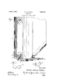
Figure 1 is a fragmentary sectional View of a portion of a headlight showing the present invention embodied therein;
Fig. 2 is a front elevational view of a clamping member utilized to hold the front glass or lens in the frame of the headlight door; and
Fig. 3 is a side elevational view of the member shown in Fig. 2.
The headlight shown in Fig. 1 comprises the usual casing 11 which is open at its front end and is adapted to receive in closely fitting relation at said end a door 12. The door 12 constitutes a frame for a front glass or lens 13, the periphery of which is embraced by a gasket 14 of rubber or other suitably resilient material. This gasket 1% is shown as being of channel formation and constituting portions overlapping the marginal portions of each side of the glass or lens 13. It will be understood, however, that two separate gaskets, respectively disposed on the two sides of the glass 13, may be utilized instead of the single channel shaped gasket 14:, if desired.
The rim portion of the door 12 is provided at suitable intervals with integral bosses 15 on the outside of said rim and at corresponding intervals with bosses'16 on the inside of said rim. The outer surfaces of the outside bosses 15 are inclined with respect to the axis of the headlight casing, while the inner surfaces of the inside bosses 16 extend in place substantially parallel to the axis of the casing.
A hole is drilled through the rim of the door 12 substantially at the middle of each of the bosses 15 and 16 and extending entirely through said bosses along an axis substantially at right angles to the inclined outer surface of the outside boss 15, as shown in Fig. 1. These holes are of the proper diameter to receive bolts or screws 17 which are inserted from the outside of the door frame so that the heads thereof are accessible from outside the headlight casing. I
The shank of each of the bolts or screws 17 extends through a slotted opening in a clamping member 18 which is oftriangularcross-section, having a surface substantially parallel to the inclined outer surface of the corresponding outside boss 15 constituting the hypothenuse of such triangular cross-section. The inner extremities of the bolts orscrews 17'are providedrwith washers 19 and nuts 20 whereby the clamping members 18 may be firmly locked in position by tightening the screws 17.
The bottom surface of each of the clamp-: ing members 18 bears against the inner surface of the corresponding inside boss 16 and the front surface of each of said clamping members bears against the inside-of the gasket 14. to force the front glass or.lens 13 against the bezel of the door frame 12. The construction of the clamping members 18 is shown in detail in Figs. 2 and 3, the former figure being a view of one of said members looking at the flat front surface thereof which bears against thegasket 14, and the latter figure being a side elevational view of one of these members.
It will be understood that a suitable number of the clamping members 18 will be pro vided around the periphery of the door frame 12 so that the front glass or lens 13 will be clamped in position at the proper intervals, two of such clamping members being shown;
in the fragmentary View constituting Fig. 1 of the drawings.
As will be apparent from an examination of the. structure disclosed, the screws or bolts 17 maybe tightenedfrom outside the headlight casing without opening the door 12 thereof. The effect of tightening these screws is to move :thevclamping members 18 r with a wedge-like action toward the front of the door 12, whereby the front surfaces of said clamping members are firmly forced against the inner surface of the gasket 14.
"This action is-effected by-reasonofthe incliings in the clamping members 18 are provided to-accommodalte. such movement of the clamping members with respect to the securing screws 17. The resiliency of the gasket '14 will absorb the pressure applied by the clamping members 18 andthus hold the front glass or lens 13 firmly in its proper position.
The clamping of the glass or lens 13 in position in the mannerdisclosed produces an entirely tight joint between said glass or lens and the frame of "the door 12 so that the internal parts of the headlight, including (the reflector, the lamp bulb, etc., are properly protected from dirt and moisture. The feature of the construction whereby'the clamping members 18 may be adjusted from outside the headlight casing without opening the door 12 permits the glass to be tightened when necessary to eliminate rattling in the shortest possible time without exposing the interior of the headlight to the external at mosphere. The replacement .of the glass .or lens 13 .in case .of breakage may be readily accomplished by opening the .door 12 and removing the screws 17 .and clamping members '18 so that the new glass and the gasket or gaskets therefor may be freely inserted, whereupon the clamping members, screws, washers and nuts 'arereplaced and tightened.
The construction herein disclosed for bolding a glass .or lens in. position in a headlight against the :glass.
2. Means for holding a glass pane in a frame or the like, comprising a plurality of retaining members substantially right-triangular incross-section, retaining screws passing through said members at right-angles to their hypothenuse surface and also through the frame, said members being slidable with their bases on the inner periphery of the frame and abutting with their sides against the glass.
In witness whereof, I have hereunto subscribed my name.
WILLIAM EDWA'RD RICHARD.
the details of construction without departing
Priority Applications (1)
| Application Number | Priority Date | Filing Date | Title |
|---|---|---|---|
| US405581A US1852791A (en) | 1928-03-07 | 1929-11-08 | Headlight |
Applications Claiming Priority (2)
| Application Number | Priority Date | Filing Date | Title |
|---|---|---|---|
| US259736A US1960922A (en) | 1928-03-07 | 1928-03-07 | Fastener |
| US405581A US1852791A (en) | 1928-03-07 | 1929-11-08 | Headlight |
Publications (1)
| Publication Number | Publication Date |
|---|---|
| US1852791A true US1852791A (en) | 1932-04-05 |
Family
ID=26947512
Family Applications (1)
| Application Number | Title | Priority Date | Filing Date |
|---|---|---|---|
| US405581A Expired - Lifetime US1852791A (en) | 1928-03-07 | 1929-11-08 | Headlight |
Country Status (1)
| Country | Link |
|---|---|
| US (1) | US1852791A (en) |
Cited By (1)
| Publication number | Priority date | Publication date | Assignee | Title |
|---|---|---|---|---|
| US2565741A (en) * | 1945-09-29 | 1951-08-28 | Miller Co | Individual fluorescent lighting fixture |
-
1929
- 1929-11-08 US US405581A patent/US1852791A/en not_active Expired - Lifetime
Cited By (1)
| Publication number | Priority date | Publication date | Assignee | Title |
|---|---|---|---|---|
| US2565741A (en) * | 1945-09-29 | 1951-08-28 | Miller Co | Individual fluorescent lighting fixture |
Similar Documents
| Publication | Publication Date | Title |
|---|---|---|
| US2281643A (en) | Head lamp | |
| US3004305A (en) | Resilient sash mounting for vehicles | |
| US2910577A (en) | Vehicle headlamp mounting | |
| US1823636A (en) | Mounting and support for rear-view mirrors | |
| US1852791A (en) | Headlight | |
| US2762908A (en) | Vehicle lamp | |
| US3225189A (en) | Lamp mount | |
| US2814720A (en) | Vehicle lamp | |
| EP1090254A1 (en) | Shockabsorbed lamp and method for manufacturing of the shockabsorbed lamp | |
| US2123125A (en) | Head lamp for vehicles | |
| US2866082A (en) | Wire spring lens retainer | |
| US1960922A (en) | Fastener | |
| US1196951A (en) | Lamp-cowl. | |
| JPS6310997Y2 (en) | ||
| US2307739A (en) | Driving light | |
| US3066218A (en) | Lamp assembly | |
| US1797540A (en) | Vehicle lamp | |
| US1183147A (en) | Mine-lamp. | |
| US2138083A (en) | Lamp structure | |
| US1334924A (en) | Lens-holder for headlights | |
| US2003343A (en) | Automobile license plate holder | |
| US1465549A (en) | Lamp | |
| US2344683A (en) | Clamp and mounting bracket | |
| US1631112A (en) | Locomotive headlight | |
| KR101974822B1 (en) | cooling module mounting bracket for automobile |