US1852785A - Extensible supporting apparatus - Google Patents
Extensible supporting apparatus Download PDFInfo
- Publication number
- US1852785A US1852785A US422731A US42273130A US1852785A US 1852785 A US1852785 A US 1852785A US 422731 A US422731 A US 422731A US 42273130 A US42273130 A US 42273130A US 1852785 A US1852785 A US 1852785A
- Authority
- US
- United States
- Prior art keywords
- support
- shoes
- supporting apparatus
- slidable
- spring
- Prior art date
- Legal status (The legal status is an assumption and is not a legal conclusion. Google has not performed a legal analysis and makes no representation as to the accuracy of the status listed.)
- Expired - Lifetime
Links
- 210000002105 tongue Anatomy 0.000 description 3
- 229940000425 combination drug Drugs 0.000 description 1
- 239000002184 metal Substances 0.000 description 1
- 238000006467 substitution reaction Methods 0.000 description 1
Images
Classifications
-
- F—MECHANICAL ENGINEERING; LIGHTING; HEATING; WEAPONS; BLASTING
- F16—ENGINEERING ELEMENTS AND UNITS; GENERAL MEASURES FOR PRODUCING AND MAINTAINING EFFECTIVE FUNCTIONING OF MACHINES OR INSTALLATIONS; THERMAL INSULATION IN GENERAL
- F16B—DEVICES FOR FASTENING OR SECURING CONSTRUCTIONAL ELEMENTS OR MACHINE PARTS TOGETHER, e.g. NAILS, BOLTS, CIRCLIPS, CLAMPS, CLIPS OR WEDGES; JOINTS OR JOINTING
- F16B7/00—Connections of rods or tubes, e.g. of non-circular section, mutually, including resilient connections
-
- F—MECHANICAL ENGINEERING; LIGHTING; HEATING; WEAPONS; BLASTING
- F21—LIGHTING
- F21V—FUNCTIONAL FEATURES OR DETAILS OF LIGHTING DEVICES OR SYSTEMS THEREOF; STRUCTURAL COMBINATIONS OF LIGHTING DEVICES WITH OTHER ARTICLES, NOT OTHERWISE PROVIDED FOR
- F21V19/00—Fastening of light sources or lamp holders
-
- F—MECHANICAL ENGINEERING; LIGHTING; HEATING; WEAPONS; BLASTING
- F21—LIGHTING
- F21Y—INDEXING SCHEME ASSOCIATED WITH SUBCLASSES F21K, F21L, F21S and F21V, RELATING TO THE FORM OR THE KIND OF THE LIGHT SOURCES OR OF THE COLOUR OF THE LIGHT EMITTED
- F21Y2103/00—Elongate light sources, e.g. fluorescent tubes
-
- Y—GENERAL TAGGING OF NEW TECHNOLOGICAL DEVELOPMENTS; GENERAL TAGGING OF CROSS-SECTIONAL TECHNOLOGIES SPANNING OVER SEVERAL SECTIONS OF THE IPC; TECHNICAL SUBJECTS COVERED BY FORMER USPC CROSS-REFERENCE ART COLLECTIONS [XRACs] AND DIGESTS
- Y10—TECHNICAL SUBJECTS COVERED BY FORMER USPC
- Y10T—TECHNICAL SUBJECTS COVERED BY FORMER US CLASSIFICATION
- Y10T403/00—Joints and connections
- Y10T403/32—Articulated members
- Y10T403/32254—Lockable at fixed position
- Y10T403/32467—Telescoping members
- Y10T403/32475—Telescoping members having detent
- Y10T403/32483—Spring biased
Definitions
- the present invention relates to extension supporting apparatus and to friction devices generally and more particularly th-e invention relates to such devices of the spring and shoe type, all of which are useful in the arts generally.
- the invention is particularly useful in relation to housings for electric discharge devices such as that set forth in pending application of Leroy J. Buttolpb, Serial lo Number 416,932, filed December 27, 1929.
- the object of the invention is to provide an extension supporting apparatus and a frictional device combining the features of rigidity, adaptability, compactness, smoothness and certainty in operation.
- the device comprises two thin metal shoes attached to the slidable member of an extension supporting apparatus and a spring through the slidable member of said apparatus adapted to press said shoes against the stationary member of said apparatus.
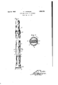
- Fig. 1 is an elevational view of the new and novel extension supporting apparatus and frctional device with the outer tubular supporting member broken away so as to show the two shoes; the position of the spring being indicated by dotted lines.
- Fig. 2 is a plan view of the invention along the line 2-2 of Fig. 1.
- Fig. 1 of the drawings 3 is a tubular support and 4 is another tubular support being concentric therewith.
- the outer diameter of support 4 is less than the inner diameter of support 3 to permit the vertical movement of support 4 in support 3 and to permit the introduction of thin shoes 5, 6 between said supports 3, 4.
- Said shoes 5. 6 are each provided with a tongue at the top thereof adapted to tit into openings in the walls of slidable support 4.
- Said tongues are indicated by dotted lines at 12 in Fig. 1, though in their normal position they are at right angles to the longitudinal axis of slidable support 4. Being so arranged said tongues maintain shoes, 6 in a fixed posi-p tion with respect to support 4 when said support 4 is moved in support 3.
- the position of said shoes 5, 6 on support 4 is such that the ends of said shoes 5, 6 are at least a short distance up from the endrof support 4. In this position said shoes 5, 6 stop said support 4 at the top of support 3 leaving a suiiicient portion of support 4 in support 3 to maintain a stiff, rigid support in respect to lateral movement for any device mounted on support 4 even when said support 4 is in fully extended position. From this it is obvious that a'stitt rigid support is maintained when support 4 is in any-intermediateposition. Lock nut 10 ⁇ is provided only as a precaution against any severe physicalshocks to which the apparatus in which the invention is used may be subject. Support 3 is firmly set into base 11, said base 11 may also act as a stop for slidable support 4. y
- 7 is a spring passing through two openings 8, 9 in the walls of hollow support 4 pressing shoes 5, 6 against the inner walls of support 3.
- the position of said spring 7 with respect to shoes 5, 6 is indicated by dotted lines in Fig. 1.
- the pressure exerted by spring 7 on shoes 5, 6 determines the force necessary to move support 4'insupport 3, so that springs of various resistance may be used determined by theweight of the object mounted on support 4 and'supported by the two members 3, 4
- the device is rigid and compact, is smooth and certain in operation and is adaptable to support objects of various weights.
- the tube 3 is telescoped into another tube mounted on the base 1l1 the friction devices 5, 6, 7, being provided on the inner' end of the tube 3 and bearing against the inner surface of the added tube and performing their usual function and, furthermore, another tube structure similar to 4;, 5, 6, 7 caribe telescoped into tube 4: to slide therein, lock nuts l0 being provided at appropriate places along the length of the multiple structure as indicated at l0 to provide a compact, smoothly Working, strong, rigid extensible support structure of light Weight and one, because of the cooperation of its members, capable of supporting articles of considerable size and 'Weight in any vertical or horizontal position of the support device.
- an extensible supporting apparatus having a plurality of members one slidable Within the otherand a friction device comprising a plurality of shoes attached to said slid'able member'and a spring through said slidable member adapted to press said shoes against the Walls of the stationary member.
- an extensiblesupporting apparatus having a plurality of members one slidable Within the other and a friction device comprising a plurality of shoes attached to said slidable member a suiiicient distance from the end thereof to resist lateral movements of the slidable member in its' extended position and a spring through said slidable member adapted to press said shoes against the inner Walls of the stationary member.
- an extensible supporting apparatus having a plurality of members one slidable Within the other and a friction device comprising a plurality of shoes attached to said slidable member, a spring through said slidable member adapted to press said shoes against the Walls of the stationary member and means for locking said members in desired position.
Landscapes
- Engineering & Computer Science (AREA)
- General Engineering & Computer Science (AREA)
- Mechanical Engineering (AREA)
- Mutual Connection Of Rods And Tubes (AREA)
Description
April 5, 1932. 0. 1 MOHLER 1,852,785
' EXTENSIBLE SUPPORTING APPARATUS Filed Jan. 25.' 1950 INVENTOR HIS )ATTORNEY Patented Apr. 5, 1932 UNITED STATES PATENT OFFICE OTTO J'. MOEHLER, 0F BLOOMFIELD, NEW JERSEY, ASSIGNOR TO GENERAL ELECTRIC VAPOR LAMP COMPANY, F HOBOKEN, NEW JERSEY, A CORPORATION OF; yNEIN JERSEY EXTENSIBLE SUPPORTING APPARATUS Application maa January 2e, 1930. seriai'No. 422,731.
The present invention relates to extension supporting apparatus and to friction devices generally and more particularly th-e invention relates to such devices of the spring and shoe type, all of which are useful in the arts generally. The invention is particularly useful in relation to housings for electric discharge devices such as that set forth in pending application of Leroy J. Buttolpb, Serial lo Number 416,932, filed December 27, 1929.
The object of the invention is to provide an extension supporting apparatus and a frictional device combining the features of rigidity, adaptability, compactness, smoothness and certainty in operation.
In accordance with the object of the invention the device comprises two thin metal shoes attached to the slidable member of an extension supporting apparatus and a spring through the slidable member of said apparatus adapted to press said shoes against the stationary member of said apparatus.
In the drawings accompanying and forming part of this specification two views of the invention are shown for purposes of illustration in which,
Fig. 1 is an elevational view of the new and novel extension supporting apparatus and frctional device with the outer tubular supporting member broken away so as to show the two shoes; the position of the spring being indicated by dotted lines.
Fig. 2 is a plan view of the invention along the line 2-2 of Fig. 1.
Referring to Fig. 1 of the drawings 3 is a tubular support and 4 is another tubular support being concentric therewith. The outer diameter of support 4 is less than the inner diameter of support 3 to permit the vertical movement of support 4 in support 3 and to permit the introduction of thin shoes 5, 6 between said supports 3, 4. Said shoes 5. 6 are each provided with a tongue at the top thereof adapted to tit into openings in the walls of slidable support 4. Said tongues are indicated by dotted lines at 12 in Fig. 1, though in their normal position they are at right angles to the longitudinal axis of slidable support 4. Being so arranged said tongues maintain shoes, 6 in a fixed posi-p tion with respect to support 4 when said support 4 is moved in support 3. The position of said shoes 5, 6 on support 4 is such that the ends of said shoes 5, 6 are at least a short distance up from the endrof support 4. In this position said shoes 5, 6 stop said support 4 at the top of support 3 leaving a suiiicient portion of support 4 in support 3 to maintain a stiff, rigid support in respect to lateral movement for any device mounted on support 4 even when said support 4 is in fully extended position. From this it is obvious that a'stitt rigid support is maintained when support 4 is in any-intermediateposition. Lock nut 10` is provided only as a precaution against any severe physicalshocks to which the apparatus in which the invention is used may be subject. Support 3 is firmly set into base 11, said base 11 may also act as a stop for slidable support 4. y
Referring to Fig. 2 of the drawings, 7 is a spring passing through two openings 8, 9 in the walls of hollow support 4 pressing shoes 5, 6 against the inner walls of support 3. The position of said spring 7 with respect to shoes 5, 6 is indicated by dotted lines in Fig. 1. The pressure exerted by spring 7 on shoes 5, 6 determines the force necessary to move support 4'insupport 3, so that springs of various resistance may be used determined by theweight of the object mounted on support 4 and'supported by the two members 3, 4
Having these structural characteristics the device is rigid and compact, is smooth and certain in operation and is adaptable to support objects of various weights.
While in the annexed claims certain new and novel features of the invention have been pointed out it will be understood that various omissions, substitutions, multiplications and changes in the form and details of the device and in the use and operation thereof may be made by those skilled in the art without departing from the broad spirit and scope of the invention. For example, instead of having a single stationary member and a sin gle slidable member the device may have a multiplicity of both by having each slidable member act as a stationary member when in an extended position. Having this structure the apparatus, is compact, and may be extended to great lengths Without losing its rigidity.
Thus, the tube 3 is telescoped into another tube mounted on the base 1l1 the friction devices 5, 6, 7, being provided on the inner' end of the tube 3 and bearing against the inner surface of the added tube and performing their usual function and, furthermore, another tube structure similar to 4;, 5, 6, 7 caribe telescoped into tube 4: to slide therein, lock nuts l0 being provided at appropriate places along the length of the multiple structure as indicated at l0 to provide a compact, smoothly Working, strong, rigid extensible support structure of light Weight and one, because of the cooperation of its members, capable of supporting articles of considerable size and 'Weight in any vertical or horizontal position of the support device.
I claim:
l. In combination an extensible supporting apparatus having a plurality of members one slidable Within the otherand a friction device comprising a plurality of shoes attached to said slid'able member'and a spring through said slidable member adapted to press said shoes against the Walls of the stationary member. A
2. In combina-tion an extensiblesupporting apparatushaving a plurality of members one slidable Within the other and a friction device comprising a plurality of shoes attached to said slidable member a suiiicient distance from the end thereof to resist lateral movements of the slidable member in its' extended position and a spring through said slidable member adapted to press said shoes against the inner Walls of the stationary member.
3. In combination an extensible supporting apparatus having a plurality of members one slidable Within the other and a friction device comprising a plurality of shoes attached to said slidable member, a spring through said slidable member adapted to press said shoes against the Walls of the stationary member and means for locking said members in desired position.
Signed at Hoboken, in the county of Hudson and State of New Jersey, this 21st day ofl January, A. D. 1930.
OTTO J. MOEHLER.
Priority Applications (1)
| Application Number | Priority Date | Filing Date | Title |
|---|---|---|---|
| US422731A US1852785A (en) | 1930-01-23 | 1930-01-23 | Extensible supporting apparatus |
Applications Claiming Priority (1)
| Application Number | Priority Date | Filing Date | Title |
|---|---|---|---|
| US422731A US1852785A (en) | 1930-01-23 | 1930-01-23 | Extensible supporting apparatus |
Publications (1)
| Publication Number | Publication Date |
|---|---|
| US1852785A true US1852785A (en) | 1932-04-05 |
Family
ID=23676112
Family Applications (1)
| Application Number | Title | Priority Date | Filing Date |
|---|---|---|---|
| US422731A Expired - Lifetime US1852785A (en) | 1930-01-23 | 1930-01-23 | Extensible supporting apparatus |
Country Status (1)
| Country | Link |
|---|---|
| US (1) | US1852785A (en) |
Cited By (13)
| Publication number | Priority date | Publication date | Assignee | Title |
|---|---|---|---|---|
| US2515829A (en) * | 1946-06-24 | 1950-07-18 | Henry H Levin | Flexible extension mop having a pivoted finger mop holding means |
| US2643143A (en) * | 1948-09-30 | 1953-06-23 | Bergqvist Ake Torgny | Locking device for telescopic structures |
| US2923513A (en) * | 1955-09-15 | 1960-02-02 | American Hospital Supply Corp | Support stand |
| US2952485A (en) * | 1956-06-21 | 1960-09-13 | Jerry J Hammond | Music stand |
| US3031085A (en) * | 1955-09-15 | 1962-04-24 | American Hospital Supply Corp | Support stand |
| US3877670A (en) * | 1973-04-18 | 1975-04-15 | Scott & Fetzer Co | Extensible support structure |
| US4278223A (en) * | 1979-08-10 | 1981-07-14 | Fauteux Denis J | Self supporting stand for hand held hair drier |
| US5152627A (en) * | 1990-03-16 | 1992-10-06 | Reiche & Co. | Telescopable steering column of power vehicle |
| US6045288A (en) * | 1997-10-20 | 2000-04-04 | M. Randall Pasternak | Adjustable telescoping utility pole |
| US20090039211A1 (en) * | 2007-08-10 | 2009-02-12 | Wei-Hsin Hsu | Elevating mechanism with an elasticity compensative function and related display device |
| CN104728230A (en) * | 2015-03-20 | 2015-06-24 | 中山市思锐摄影器材工业有限公司 | A telescopic tube structure |
| US20220056939A1 (en) * | 2020-08-21 | 2022-02-24 | Pivot Point, Incorporated | Self-locking pin |
| USD1067220S1 (en) * | 2024-11-21 | 2025-03-18 | Shenzhen Xunweijia Technology Development Co., Ltd. | Desktop stand |
-
1930
- 1930-01-23 US US422731A patent/US1852785A/en not_active Expired - Lifetime
Cited By (16)
| Publication number | Priority date | Publication date | Assignee | Title |
|---|---|---|---|---|
| US2515829A (en) * | 1946-06-24 | 1950-07-18 | Henry H Levin | Flexible extension mop having a pivoted finger mop holding means |
| US2643143A (en) * | 1948-09-30 | 1953-06-23 | Bergqvist Ake Torgny | Locking device for telescopic structures |
| US2923513A (en) * | 1955-09-15 | 1960-02-02 | American Hospital Supply Corp | Support stand |
| US3031085A (en) * | 1955-09-15 | 1962-04-24 | American Hospital Supply Corp | Support stand |
| US2952485A (en) * | 1956-06-21 | 1960-09-13 | Jerry J Hammond | Music stand |
| US3877670A (en) * | 1973-04-18 | 1975-04-15 | Scott & Fetzer Co | Extensible support structure |
| US4278223A (en) * | 1979-08-10 | 1981-07-14 | Fauteux Denis J | Self supporting stand for hand held hair drier |
| US5152627A (en) * | 1990-03-16 | 1992-10-06 | Reiche & Co. | Telescopable steering column of power vehicle |
| US6045288A (en) * | 1997-10-20 | 2000-04-04 | M. Randall Pasternak | Adjustable telescoping utility pole |
| US20090039211A1 (en) * | 2007-08-10 | 2009-02-12 | Wei-Hsin Hsu | Elevating mechanism with an elasticity compensative function and related display device |
| US8079563B2 (en) * | 2007-08-10 | 2011-12-20 | Qisda Corporation | Elevating mechanism with an elasticity compensative function and related display device |
| CN104728230A (en) * | 2015-03-20 | 2015-06-24 | 中山市思锐摄影器材工业有限公司 | A telescopic tube structure |
| CN104728230B (en) * | 2015-03-20 | 2017-10-03 | 广东思锐光学股份有限公司 | A kind of flexible pipe structure |
| US20220056939A1 (en) * | 2020-08-21 | 2022-02-24 | Pivot Point, Incorporated | Self-locking pin |
| US11542977B2 (en) * | 2020-08-21 | 2023-01-03 | Pivot Point Incorporated | Self-locking pin |
| USD1067220S1 (en) * | 2024-11-21 | 2025-03-18 | Shenzhen Xunweijia Technology Development Co., Ltd. | Desktop stand |
Similar Documents
| Publication | Publication Date | Title |
|---|---|---|
| US1852785A (en) | Extensible supporting apparatus | |
| US1919114A (en) | Lamp stand | |
| US2719688A (en) | Telescopic tubes | |
| US1107075A (en) | Display device. | |
| US2090550A (en) | Adjustable lock | |
| US2934211A (en) | Dispensing apparatus | |
| ES420374A1 (en) | Thermally deformable fastening pin | |
| US3248756A (en) | Expanding device for plastic pipe | |
| US1372100A (en) | Routing-rack | |
| US2739027A (en) | Multi-position lock slide | |
| US2771261A (en) | Telescoping tripod leg | |
| RU2017137414A (en) | TANK WITH SUPPORTING STRUCTURE, SUPPLIED BY CURRENT MECHANISM | |
| GB270169A (en) | Improvements in coiled springs | |
| US2372204A (en) | Tubular remote-control device | |
| US2437510A (en) | Telescoping joint | |
| US2778593A (en) | Collapsible stands | |
| US960718A (en) | Level attachment for drills. | |
| US2837945A (en) | Bar steadier for seamless tubing mills | |
| US377995A (en) | Pneumatic holder for mirrors and other articles | |
| US1776859A (en) | Binding post | |
| US3709453A (en) | Vertically and circularly displaceable support | |
| US1955773A (en) | Display fixture | |
| US1190356A (en) | Gun-carriage. | |
| US1465464A (en) | Casserole holder | |
| US1070144A (en) | Curtain rod and bracket. |