US1852774A - Translating device - Google Patents
Translating device Download PDFInfo
- Publication number
- US1852774A US1852774A US336474A US33647429A US1852774A US 1852774 A US1852774 A US 1852774A US 336474 A US336474 A US 336474A US 33647429 A US33647429 A US 33647429A US 1852774 A US1852774 A US 1852774A
- Authority
- US
- United States
- Prior art keywords
- pole
- casing
- cover
- conductors
- pieces
- Prior art date
- Legal status (The legal status is an assumption and is not a legal conclusion. Google has not performed a legal analysis and makes no representation as to the accuracy of the status listed.)
- Expired - Lifetime
Links
- 239000004020 conductor Substances 0.000 description 27
- 238000004804 winding Methods 0.000 description 9
- 238000010276 construction Methods 0.000 description 7
- 210000000080 chela (arthropods) Anatomy 0.000 description 3
- 239000011810 insulating material Substances 0.000 description 2
- 238000004519 manufacturing process Methods 0.000 description 2
- 239000000126 substance Substances 0.000 description 2
- 230000009471 action Effects 0.000 description 1
- 210000000988 bone and bone Anatomy 0.000 description 1
- 108010052322 limitin Proteins 0.000 description 1
- 230000007246 mechanism Effects 0.000 description 1
- 239000003973 paint Substances 0.000 description 1
- 230000004044 response Effects 0.000 description 1
- 125000006850 spacer group Chemical group 0.000 description 1
Images

Classifications
-
- G—PHYSICS
- G02—OPTICS
- G02F—OPTICAL DEVICES OR ARRANGEMENTS FOR THE CONTROL OF LIGHT BY MODIFICATION OF THE OPTICAL PROPERTIES OF THE MEDIA OF THE ELEMENTS INVOLVED THEREIN; NON-LINEAR OPTICS; FREQUENCY-CHANGING OF LIGHT; OPTICAL LOGIC ELEMENTS; OPTICAL ANALOGUE/DIGITAL CONVERTERS
- G02F1/00—Devices or arrangements for the control of the intensity, colour, phase, polarisation or direction of light arriving from an independent light source, e.g. switching, gating or modulating; Non-linear optics
- G02F1/01—Devices or arrangements for the control of the intensity, colour, phase, polarisation or direction of light arriving from an independent light source, e.g. switching, gating or modulating; Non-linear optics for the control of the intensity, phase, polarisation or colour
- G02F1/09—Devices or arrangements for the control of the intensity, colour, phase, polarisation or direction of light arriving from an independent light source, e.g. switching, gating or modulating; Non-linear optics for the control of the intensity, phase, polarisation or colour based on magneto-optical elements, e.g. exhibiting Faraday effect
Definitions
- This invention relates to translating devices or light valves, whereby the amount of light transmitted from a light source is varied in response to variations in an electric current and has special reference to improvements in the construction of a light valve and in the arrangement and construction of the devices employed for adjusting all the essential elements.
- the light valve as disclosed in the patent to E. C. Wente provides a construction which is entirely satisfactory for use in general cases where no narrow limit is to be placed on the space allowable for the mounting and the surrounding space necessary for adjustment of the light valve.
- space is a limitin factor, for example, in adapting the light valve for use in a motion picture camera,
- a compact construction is desirable, which necessarily limits the space allowable between the essential elements and also the amount of space to be allotted to the adjusting devices. While it is desirable to combine the adjusting devices in a minimum space, it is primarily essential that such devices afford accurate adjustment and that they be accessible for adjustment.
- the conductors which form the light transmitting slot are extremely delicate and require fine adjustments both as to proper tension to be applied and as to their position between the pole ieces. In the preparation of the light valve or operation, it is preferable to apply final tension to these conductors after the light valve has been assembled and for this reason accurate means for adjusting the conductors from the exterior of the casing is desirable.
- the improvements which are the subject of this invention have for an object the production of a device of the type described of compact construction, having a great facility of adjustment and a high degree of accuracy of adjustment and operation.
- a light valve which is of a compact construction incorporating novel features to give added facility of operation and adjustment.
- the light valve designed in accordance with the invention comprises a casing containing the field windings and one polepiece, and a detachable head, bearing on its inner face all the necessary adjusting devices combined into one unit built up from a flat surface of the detachable head and forming a unitary structure therewith.
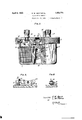
- FIG. 1 is a perspective view of the assembled light valve.
- Fig. 2 is a perspective view of the casing with the cover removed.
- Fig. 3 is a side elevation of the valve, partly in section.
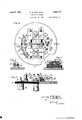
- Fig. 4 is a plan view of the interior of'the casing cover showing the general arrangement of the different adjusting devices forming the unitary structure.
- Fig. 5 is an elevation partly in section of the showing of Fig. 4.
- Fig. 6 is a sectional view taken along line 66 of Fig. 4.
- Fig. 7 is a sectional. view taken along line 7-7 of Fig. 4.
- Fig. 8 is a sectional view taken along line 88 of Fig. 4.
- Fig. 9 is a sectional view taken along line 9-9 of Fig. 4.
- the reference numeral 1 indicates the light valve casing provided with a casing cover 2 adapted to be held in a definite position by means of projections 4 and to be secured to the casing by means of a knurled annular ring 3 which is provided with an internal screw thread to engage the thread 10 (Fig. 5) of the cover.
- the casing 1 contains a field winding 7 and one polepiece 5.
- the strip 8 provides a mounting to which field winding leads 9 are attached to possibility that some slight inaccuracy in facilitate connection to the external source of current.
- pole-piece 5 is secured to the casing by means of screws 11, while the pole-piece 6 is secured to the casing cover by means of screws 12.
- the bearing surface between the casing and the interior marginal edge of the casing cover might be relied upon to insure satisfactory spacing, but there is the manufacture at the point of contact between the casing and the casing cover would cause a greater inaccuracy in the spacing of the pole-pieces by reason of this slight inaccuracy becoming magnified due to the distance from the bearing surface to the pole-pieces.
- spacing studs 13 and 14 are placed as near the polepieces as is conveniently possible and secured by means of screws to the casing cover 2. These spacing'studs are accurately machined to a height exceeding the combined height of the pole-pieces an amount sufficient to allow the proper space between the pole-faces. The ends of studs 13 and 14 butt against the flanged portions 47 and 48 respectively of the pole-piece 5.
- Pins 15 are inserted in the side of the easing to prevent the ring 3 from slipping off the casing when it is not being used to engage the cover 2.
- Binding posts 16 and 17 are provided on the exterior of the cover to facilitate connection of the filament circuit to an external source of sound modulated current.
- Fig. 4 it will be seen that one end of the conductor or filament 18 is secured to take-up screw 19 and from there it is drawn across the pole-piece 6, but not in engagement therewith, as the filament lies in a small channel or recess provided in the pole-face.
- the filament is then passed around an idler pulley 20, made of some suitable insulating material, and from there back over the pole-piece 6 and terminated at take-up screw 21. Sound modulated currents are supplied to this filament through conductors 22 and 23 which are connected to the binding posts 16 and 17.
- the takeup screws 19 and 21 are adapted to be used as preliminary tensioning devices for the filament.
- adjusting elements 26 and 27 to be placedon opposite sides of the pole-piece 6.
- reference numeral 26 indicates a block of insulating material such as bone, ivory or some other suitable substance shaped as shown in Fig. 7.
- Fig. 7 shows only one-half of this adjusting device but as the two sides are 7 sides of the filaments are formed from a single block of the substance to be used.
- An internally threaded collar 28 is inserted in the block 26 and held in place by means of set screw 29.
- the movement of the pincer 30 is accomplished by means of a Vernier differ-' ential screw composed of an internally and externally threaded screw 31 and a screw 32 having on one end the pincer30.
- the screw 32 engages the internal thread of the screw 31.
- a spring 33 is provided to take up any lost motion in the differential screw.
- An exceedingly fine adjustment of the filament 18 and therefore the proper space relation between the filaments can be obtained by the use of such an adjusting element.
- the pincer members 30 With ref erence to the element as a whole it will be seen in Fig. 4 that the pincer members 30 are oppositely disposed and are so shaped that a very small portion ,of the pincer itself makes contact with the filament.
- a strip of ivory "ferential adjusting screws are provided so that each of the two filaments forming the light valve may be spacially adjusted just beyond each of the bridges which support said filaments.
- tensioning member consists of a bracket 35 pivoted at the point 36 and held under tension by means of spring 37.
- This bracket 35 has two extensions 38 and'39 to which is riveted a spring 40.
- the bracket bears against a cam member in the form of a cone 41, arranged to be advanced by means of a-threaded portion, cooperating with a threaded hole in the coy'er of the housing.
- the controlling screw for cam 41 extends to the exterior of the cover through a cylindrical guide. It will readily be seen that as the screw 41 is moved outward the bracket 35 will also move outward thereby causing the spring to exert a tension on the filament 18.
- the spring 40 will take up any slack produced in the conductors. This slack is usually caused by the expansion of the conductors due to the heat produced by the sound modulated currents.
- the numeral 43 indicates a circular recess adapted to receive a lens tube to be associated with the recording film in a motion picture camera or other sound recording mechanism.
- Light emanating from a lamp enters the valve at 44, passes through the light transmitting slot formed by the filaments 18, and through'passage onto the film through the lens system provided. To prevent light reflection in the passages 44 and 45 they are threaded as shown and coated with a non-reflecting black paint.
- the cover may be quickly removed by releasing ring 3.
- a slight turn of this ring will release the cover thereby leaving the casing in position while the trouble present in the elements mounted on the cover is eliminated.
- a light valve having oppositely disposed pole-pieces for setting up a constant magnetic field and conductors supplied with modulated electrical currents suspended between said pole-pieces to form a light transmitting slot, said pole pieces having aligned apertures, a casing containing the field windings and one of said polepieces, a cover for said casing, said cover bearing on its inner surface as a unit structure therewith said other pole-piece and said conductors suspended adjacent the aperture in said other pole piece.
- a light valve having oppositely disposed pole-pieces for setting up a constant magnetic field and conductors supplied with modulated electrical currents suspended between said pole-pieces to form a light transmitting slot, a casing containing the field windings and one of said pole-pieces, a cover for said casing, said cover bearing on its inner surface as a unit structure therewith the said other pole-piece, said conductors and the adjusting device for adiusting the. nnsitinn of said conductors with respect to said other pole piece.
- a light valve having oppositely disposed pole-pieces for setting up a constant magnetic field and conductors supplied with modulated electrical currents suspended between said pole-pieces to form a light transmitting slot, a casing containing the field windings and one of said pole pieces, a cover for said casing, said cover bearing on its inner surface as a unit structure therewith the said other pole-piece, said conductors and the spacing means for said pole-pieces.
- a light valve having oppositely disposed pole-pieces for setting up a constant magnetic field and conductors supplied with modulated electrical currents suspended between said pole-pieces to form a light transmitting slot, a casing containing the field windings and one of said pole-pieces, a cover for said casing, said cover bearing on its inner surface as a unit structure therewith the said other pole-piece, said conductors, the adjusting and tensioning devices for said conductors, and the spacing meansfor said pole pieces.
- said spacing means comprising apair of spacer studs on opposite sides and adjacent said other pole piece.
- a light valve having oppositely disposed pole pieces for setting up a constant magnetic field and conductors supplied with modulated electrical currents suspended between said pole pieces to form a light transmitting slot, a casing containing the field windings and one of said pole pieces, a cover for said casing, said cover bearing on its inner surface as a unit structure therewith, the said other pole piece, said conductors and the tensioning device for said conductors, said tensioning device comprising an adjusting surface controlled by a member extending through said cover, a support pivoted on said cover and held against said surface by spring means, a spring mounted on the free end of said support, an extension secured to the right portion of said spring, a pulley mounted on said extension, and means including said adjusting surface, and said support to control the movement of said spring and the pulley carried thereby.
- a tensioning means for said conductors comprising a cam operated adjusting member, a spring mounted on said member, a pulley and a support therefor mounted on said spring, the movement'of said spring and the pulley carried thereby being confirolled by said cam operated adjusting mem- 8.
- a light valve having oppositely disposed pole pieces for setting up a constant magnetic field and conductors supplied with modulated electrical currents suspended between said pole pieces to form a light transmitting slot, a casing containing the field windings and one of said pole pieces, a cover for said casing, said cover bearing on its inner surface as a unit structure therewith, said other pole piece, said conductors and the adjus'ting device for said conductors, said adjusting device comprising a block member secured to said cover, oppositely disposed spacing members carried by said block member, Vernier adjusting elements in said block member, and means including said Vernier elements to control movement of each of'said spacing members.
- An electrical indicating device comprising a plurality of magnet elements for setting up a constant magnetic field, electrical conducting elements supplied from sources of currents to be indicated and suspended between said magnets, the positioning of said conducting elements responsive to said field and said currents giving an indication of variation in the supplied currents, a casing containing at least one of said magnet elements, 1
- an electrical indicating device comprising oppositely disposed magnet elements for setting up a constant magnetic field, an electrical conducting element supplied from a source of current to be indicated, said conducting element suspended between said magnet elements and responsive to said field and said current in such manner as to give an indication of variation in the supplied cur-,
- a casing containing one of said magnet elements and a cover for said casing including as a unit structure therewith the other magnet element, said conducting element,
Landscapes
- Physics & Mathematics (AREA)
- Nonlinear Science (AREA)
- Engineering & Computer Science (AREA)
- Power Engineering (AREA)
- General Physics & Mathematics (AREA)
- Optics & Photonics (AREA)
- External Artificial Organs (AREA)
Description
April 1932- E. w. GENT-ET AL 1,852,774
THANSLATING' DEVICE Filed Jan. 31, 1929 3Sheets-Sheet' 1 E W GENT //v N 0R5:
V5 2 LM Porrs q' H E TTORNEY April 5, 9 E. w. GENT ET AL 1,352,774
I TRANSLATINGJDEVICE Filed Jan. 51, 1929 a sheets-sheet 2 Fla. .5.
.FiacSg I I v 56.9.
37 r g /ja 2 k\\\\\\\ \w Em GENT q IL mug; TORNEY A ril 5,1932.
E. w. GENT ET AL TRANSLATING bEvIcE Filed Jan. 31, 1929 3 Sheets-Sheet 3 Patented Apr. 5, 1932 UNITED STATES PATENT OFFICE EDGAR W. GENT, OF MORRISTOWN, AND LOUIS M. POTTS, OF TENAFLY, N EW JERSEY, AS-
SIGNOBS TO BELL TELEPHONE LABORATORIES, INCORPORATED, OF NEW YORK, N. Y.,
A CORPORATION OF NEW YORK TRANSLATING DEVICE Application filed January 31, 1929. Serial No. 336,474.
This invention relates to translating devices or light valves, whereby the amount of light transmitted from a light source is varied in response to variations in an electric current and has special reference to improvements in the construction of a light valve and in the arrangement and construction of the devices employed for adjusting all the essential elements.
The principle of operation for such a light valve is disclosed in the U. S. patent to E. C. Wente, No. 1,638,555, wherein a pair of electrical conductors are arranged in a plane at right angles to a magnetic field so as to define a slot through which light is transmitted. Varying electrical currents supplied to these conductors cause them to move relative to each other, thus varying the width of the slot and the amount of light transmitted.
The light valve as disclosed in the patent to E. C. Wente provides a construction which is entirely satisfactory for use in general cases where no narrow limit is to be placed on the space allowable for the mounting and the surrounding space necessary for adjustment of the light valve. In cases where space is a limitin factor, for example, in adapting the light valve for use in a motion picture camera,
a compact construction is desirable, which necessarily limits the space allowable between the essential elements and also the amount of space to be allotted to the adjusting devices. While it is desirable to combine the adjusting devices in a minimum space, it is primarily essential that such devices afford accurate adjustment and that they be accessible for adjustment. The conductors which form the light transmitting slot are extremely delicate and require fine adjustments both as to proper tension to be applied and as to their position between the pole ieces. In the preparation of the light valve or operation, it is preferable to apply final tension to these conductors after the light valve has been assembled and for this reason accurate means for adjusting the conductors from the exterior of the casing is desirable. The improvements which are the subject of this invention have for an object the production of a device of the type described of compact construction, having a great facility of adjustment and a high degree of accuracy of adjustment and operation.
In accordance with the invention there is provided a light valve which is of a compact construction incorporating novel features to give added facility of operation and adjustment. The light valve designed in accordance with the invention comprises a casing containing the field windings and one polepiece, and a detachable head, bearing on its inner face all the necessary adjusting devices combined into one unit built up from a flat surface of the detachable head and forming a unitary structure therewith.
Other advantages to be found in details of construction and operation will be apparent from the description of the accompanying drawings, in which Fig. 1 is a perspective view of the assembled light valve.
Fig. 2 is a perspective view of the casing with the cover removed.
Fig. 3 is a side elevation of the valve, partly in section.
Fig. 4 is a plan view of the interior of'the casing cover showing the general arrangement of the different adjusting devices forming the unitary structure.
Fig. 5 is an elevation partly in section of the showing of Fig. 4.
Fig. 6 is a sectional view taken along line 66 of Fig. 4.
Fig. 7 is a sectional. view taken along line 7-7 of Fig. 4.
Fig. 8 is a sectional view taken along line 88 of Fig. 4. I
Fig. 9 is a sectional view taken along line 9-9 of Fig. 4.
In Figs. 1 and 2, the reference numeral 1 indicates the light valve casing provided with a casing cover 2 adapted to be held in a definite position by means of projections 4 and to be secured to the casing by means of a knurled annular ring 3 which is provided with an internal screw thread to engage the thread 10 (Fig. 5) of the cover. The casing 1 contains a field winding 7 and one polepiece 5. The strip 8 provides a mounting to which field winding leads 9 are attached to possibility that some slight inaccuracy in facilitate connection to the external source of current.
Referring now to Fig. 3 which shows a side elevation of the assembled light valve partly in section, pole-piece 5 is secured to the casing by means of screws 11, while the pole-piece 6 is secured to the casing cover by means of screws 12. It is essential to the proper operation of the valve that the faces of the polepieces 5 and 6 be accurately spaced a definite distance apart. The bearing surface between the casing and the interior marginal edge of the casing cover might be relied upon to insure satisfactory spacing, but there is the manufacture at the point of contact between the casing and the casing cover would cause a greater inaccuracy in the spacing of the pole-pieces by reason of this slight inaccuracy becoming magnified due to the distance from the bearing surface to the pole-pieces.
In accordance with this invention, spacing studs 13 and 14 are placed as near the polepieces as is conveniently possible and secured by means of screws to the casing cover 2. These spacing'studs are accurately machined to a height exceeding the combined height of the pole-pieces an amount sufficient to allow the proper space between the pole-faces. The ends of studs 13 and 14 butt against the flanged portions 47 and 48 respectively of the pole-piece 5.
Referring now to Fig. 4, it will be seen that one end of the conductor or filament 18 is secured to take-up screw 19 and from there it is drawn across the pole-piece 6, but not in engagement therewith, as the filament lies in a small channel or recess provided in the pole-face. The filament is then passed around an idler pulley 20, made of some suitable insulating material, and from there back over the pole-piece 6 and terminated at take-up screw 21. Sound modulated currents are supplied to this filament through conductors 22 and 23 which are connected to the binding posts 16 and 17. The takeup screws 19 and 21 are adapted to be used as preliminary tensioning devices for the filament. By reference to Fig. 5 it will be seen that the take-up screw 19 is inserted in a slit cut in a block 24. When suflicient tension has been applied to the filament by means of take-up screw 19 the screw 25 is tightened. The friction exerted between the screw 19 and the block 24 due to the clamping action of the block holds the takeup screw in the adjusted position. This preliminary tensioning element forms no part of this invention.
To obtain accurate and reliable operation the filaments must be in exact space relation to each other and be in alignment across the face of the pole-piece. In accordance with this invention there are provided two adjusting elements 26 and 27 to be placedon opposite sides of the pole-piece 6. A description of these adjusting elements will be made in connection with Figs. 4 and 7 in which reference numeral 26 indicates a block of insulating material such as bone, ivory or some other suitable substance shaped as shown in Fig. 7. Fig. 7 shows only one-half of this adjusting device but as the two sides are 7 sides of the filaments are formed from a single block of the substance to be used. An internally threaded collar 28 is inserted in the block 26 and held in place by means of set screw 29. The movement of the pincer 30 is accomplished by means of a Vernier differ-' ential screw composed of an internally and externally threaded screw 31 and a screw 32 having on one end the pincer30. The screw 32 engages the internal thread of the screw 31. A spring 33 is provided to take up any lost motion in the differential screw. An exceedingly fine adjustment of the filament 18 and therefore the proper space relation between the filaments can be obtained by the use of such an adjusting element. With ref erence to the element as a whole it will be seen in Fig. 4 that the pincer members 30 are oppositely disposed and are so shaped that a very small portion ,of the pincer itself makes contact with the filament. A strip of ivory "ferential adjusting screws are provided so that each of the two filaments forming the light valve may be spacially adjusted just beyond each of the bridges which support said filaments.
Final tension is applied to the filaments after the light valve is assembled. This final tension is applied to the light valve by means of the device shown in Figs. 6 and 8. The
tensioning member consists of a bracket 35 pivoted at the point 36 and held under tension by means of spring 37. This bracket 35 has two extensions 38 and'39 to which is riveted a spring 40. To the bight portion of this spring 40 is connected an extension bearing the idler or pulley 20 around which the filament 18 is passed. The bracket bears against a cam member in the form of a cone 41, arranged to be advanced by means of a-threaded portion, cooperating with a threaded hole in the coy'er of the housing. The controlling screw for cam 41 extends to the exterior of the cover through a cylindrical guide. It will readily be seen that as the screw 41 is moved outward the bracket 35 will also move outward thereby causing the spring to exert a tension on the filament 18. During the operation of the valve the spring 40 will take up any slack produced in the conductors. This slack is usually caused by the expansion of the conductors due to the heat produced by the sound modulated currents.
Referring again to Fig. 3 the numeral 43 indicates a circular recess adapted to receive a lens tube to be associated with the recording film in a motion picture camera or other sound recording mechanism. Light emanating from a lamp enters the valve at 44, passes through the light transmitting slot formed by the filaments 18, and through'passage onto the film through the lens system provided. To prevent light reflection in the passages 44 and 45 they are threaded as shown and coated with a non-reflecting black paint.
In the event of trouble in the valve after it has been finally prepared for operation and put into position for use the cover may be quickly removed by releasing ring 3. As a triple pitch thread is employed a slight turn of this ring will release the cover thereby leaving the casing in position while the trouble present in the elements mounted on the cover is eliminated.
What is claimed is:
1. In a light valve having oppositely disposed pole-pieces for setting up a constant magnetic field and conductors supplied with modulated electrical currents suspended between said pole-pieces to form a light transmitting slot, said pole pieces having aligned apertures, a casing containing the field windings and one of said polepieces, a cover for said casing, said cover bearing on its inner surface as a unit structure therewith said other pole-piece and said conductors suspended adjacent the aperture in said other pole piece.
2. In a light valve having oppositely disposed pole-pieces for setting up a constant magnetic field and conductors supplied with modulated electrical currents suspended between said pole-pieces to form a light transmitting slot, a casing containing the field windings and one of said pole-pieces, a cover for said casing, said cover bearing on its inner surface as a unit structure therewith the said other pole-piece, said conductors and the adjusting device for adiusting the. nnsitinn of said conductors with respect to said other pole piece.
3. In a light valve having oppositely disposed pole-pieces for setting up a constant magnetic field and conductors supplied with modulated electrical currents suspended between said pole-pieces to form a light transmitting slot, a casing containing the field windings and one of said pole pieces, a cover for said casing, said cover bearing on its inner surface as a unit structure therewith the said other pole-piece, said conductors and the spacing means for said pole-pieces.
4. In a light valve having oppositely disposed pole-pieces for setting up a constant magnetic field and conductors supplied with modulated electrical currents suspended between said pole-pieces to form a light transmitting slot, a casing containing the field windings and one of said pole-pieces, a cover for said casing, said cover bearing on its inner surface as a unit structure therewith the said other pole-piece, said conductors, the adjusting and tensioning devices for said conductors, and the spacing meansfor said pole pieces.
5. A light valve in accordance with claim 4, said spacing means comprising apair of spacer studs on opposite sides and adjacent said other pole piece.
6. In a light valve having oppositely disposed pole pieces for setting up a constant magnetic field and conductors supplied with modulated electrical currents suspended between said pole pieces to form a light transmitting slot, a casing containing the field windings and one of said pole pieces, a cover for said casing, said cover bearing on its inner surface as a unit structure therewith, the said other pole piece, said conductors and the tensioning device for said conductors, said tensioning device comprising an adjusting surface controlled by a member extending through said cover, a support pivoted on said cover and held against said surface by spring means, a spring mounted on the free end of said support, an extension secured to the right portion of said spring, a pulley mounted on said extension, and means including said adjusting surface, and said support to control the movement of said spring and the pulley carried thereby.
7. In a light valve having oppositely disposed pole-pieces for setting up a constant.
magnetic field and conductors supplied with modulated electrical currents sus ended between said pole-pieces to form a light transmitting slot, a tensioning means for said conductors comprising a cam operated adjusting member, a spring mounted on said member, a pulley and a support therefor mounted on said spring, the movement'of said spring and the pulley carried thereby being confirolled by said cam operated adjusting mem- 8. In a light valve having oppositely disposed pole pieces for setting up a constant magnetic field and conductors supplied with modulated electrical currents suspended between said pole pieces to form a light transmitting slot, a casing containing the field windings and one of said pole pieces, a cover for said casing, said cover bearing on its inner surface as a unit structure therewith, said other pole piece, said conductors and the adjus'ting device for said conductors, said adjusting device comprising a block member secured to said cover, oppositely disposed spacing members carried by said block member, Vernier adjusting elements in said block member, and means including said Vernier elements to control movement of each of'said spacing members.
9. An electrical indicating device comprising a plurality of magnet elements for setting up a constant magnetic field, electrical conducting elements supplied from sources of currents to be indicated and suspended between said magnets, the positioning of said conducting elements responsive to said field and said currents giving an indication of variation in the supplied currents, a casing containing at least one of said magnet elements, 1
and a cover for said casing including as a unit structure therewith another of said magnets, said conducting elements,-and means for adjusting the position of said conducting element with respect to said last mentioned magnet element.
10. In an electrical indicating device comprising oppositely disposed magnet elements for setting up a constant magnetic field, an electrical conducting element supplied from a source of current to be indicated, said conducting element suspended between said magnet elements and responsive to said field and said current in such manner as to give an indication of variation in the supplied cur-,
rent, a casing containing one of said magnet elements and a cover for said casing including as a unit structure therewith the other magnet element, said conducting element,
and means for adjusting the position of said conducting element with respect to said other magnet element. In witness whereof, I hereunto subscribe my name this 19th day of January, 1929.
EDGAR W. GENT. In witness whereof, I hereunto subscribe my name this 21st day of January, 1929.
LOUIS M. POTTS.
Priority Applications (1)
| Application Number | Priority Date | Filing Date | Title |
|---|---|---|---|
| US336474A US1852774A (en) | 1929-01-31 | 1929-01-31 | Translating device |
Applications Claiming Priority (1)
| Application Number | Priority Date | Filing Date | Title |
|---|---|---|---|
| US336474A US1852774A (en) | 1929-01-31 | 1929-01-31 | Translating device |
Publications (1)
| Publication Number | Publication Date |
|---|---|
| US1852774A true US1852774A (en) | 1932-04-05 |
Family
ID=23316252
Family Applications (1)
| Application Number | Title | Priority Date | Filing Date |
|---|---|---|---|
| US336474A Expired - Lifetime US1852774A (en) | 1929-01-31 | 1929-01-31 | Translating device |
Country Status (1)
| Country | Link |
|---|---|
| US (1) | US1852774A (en) |
-
1929
- 1929-01-31 US US336474A patent/US1852774A/en not_active Expired - Lifetime
Similar Documents
| Publication | Publication Date | Title |
|---|---|---|
| US1927346A (en) | Electromagnetic device | |
| US3082674A (en) | Automatic exposure mechanism with magnetic control of iris blades | |
| US2318359A (en) | Electromagnet | |
| US1852774A (en) | Translating device | |
| US2615778A (en) | Means for multiple recording on film | |
| US1849831A (en) | Apparatus for measuring irregularity of movement | |
| US2419100A (en) | Xdynamometer t type electrical | |
| US2550720A (en) | richardson | |
| US1871361A (en) | Indicating device | |
| US2513900A (en) | Moving coil instrument with mag | |
| US2282590A (en) | Galvanometer | |
| US2267545A (en) | Light valve | |
| US2207064A (en) | Oscillograph galvanometer | |
| US1638555A (en) | Translating device | |
| US2065907A (en) | Translating device | |
| US1943112A (en) | Light valve | |
| US1860740A (en) | Oscillograph | |
| US2055654A (en) | Sound picture recording system | |
| US1883098A (en) | Electrical resistance device | |
| US2541355A (en) | Relay with passive springs | |
| US3882389A (en) | Meter construction | |
| US2239837A (en) | Telephone receiver | |
| US2493060A (en) | Electrical control device | |
| US2832048A (en) | Adjustment assembly for watthour meters | |
| US3133159A (en) | Magnetic record-playback head |