US1852769A - Interference determining - Google Patents
Interference determining Download PDFInfo
- Publication number
- US1852769A US1852769A US320789A US32078928A US1852769A US 1852769 A US1852769 A US 1852769A US 320789 A US320789 A US 320789A US 32078928 A US32078928 A US 32078928A US 1852769 A US1852769 A US 1852769A
- Authority
- US
- United States
- Prior art keywords
- cable
- interference
- coil
- noise
- magnitude
- Prior art date
- Legal status (The legal status is an assumption and is not a legal conclusion. Google has not performed a legal analysis and makes no representation as to the accuracy of the status listed.)
- Expired - Lifetime
Links
- 239000004020 conductor Substances 0.000 description 9
- 230000011664 signaling Effects 0.000 description 4
- 230000002452 interceptive effect Effects 0.000 description 3
- 238000000034 method Methods 0.000 description 3
- 230000001939 inductive effect Effects 0.000 description 2
- 235000012905 Brassica oleracea var viridis Nutrition 0.000 description 1
- 244000064816 Brassica oleracea var. acephala Species 0.000 description 1
- 230000005540 biological transmission Effects 0.000 description 1
- 230000006698 induction Effects 0.000 description 1
- 238000009434 installation Methods 0.000 description 1
Images
Classifications
-
- H—ELECTRICITY
- H04—ELECTRIC COMMUNICATION TECHNIQUE
- H04B—TRANSMISSION
- H04B3/00—Line transmission systems
- H04B3/02—Details
- H04B3/28—Reducing interference caused by currents induced in cable sheathing or armouring
Definitions
- This invention relates to electrical measuring systems and particularly to systems for measuring small currents induced in electrical communication lines.
- An object of this invention is to provide a simple and accurate measuring circuit for obtaining this data.
- the invention is a method of determining what would be the magnitude of interference I from a power line at a point in a prospective neighboring signaling cable which comprises introducing an electrostatically shielded test conductor at that point, amplifying the induced currents and comparing the noise magnitude with a noise standard.
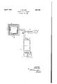
- the apparatus comprises a coil 1 encased in an electrostatic shield 9. To the terminals of this coil is connected a double-pole double-throw switch 2. This switch permits the coil to be connected to an amplifier 3 in whose out ut is situated a receiver 4 which may be of the ordinary telephone headset type. The switch 2 may be so moved that it connects the input of am lifier 3 to. a noise measuring set 5, 6, instea of to the coil 1.
- the noise measuring set consists of a potentiometer 5 and a standard vibrating element or noise standard 6, well known in the art.
- the potentiometer 5 is provided with a scale giving readings proportional to the noise transmitted.
- the coil 1 is placed in the position where it appears suitable to lay the cable, and the switch 2 is moved so as to couple the coil 1 to the amplifier 3.
- the magnitude of the noise is heard in receiver 4.
- the switch 2 is now thrown over and the noise measuring set 5, 6 is connected to the amplifier.
- Potentiometer 5 is now adjusted until the noise heard in the receiver 4 is judged to be the same as that in the first instance when it was connected to the coil 1.
- the reading of the potentiometer scale gives the value of the noise transmitted.
- the cover has a gap or osition in s which to lay the cable mayrea ily be obdiscontinuity 7 so as to prevent a neutraliza- 7 tion of the induction in coil 1 as would otherwise occur.
- the cover should be grounded as shown at What is claimed is:
- a measuring system for determining the inductive interference e'fl'ect that an interfering line would produce in an electro-statically shielded conductor of a communication cable at a point in the neighborhood of the interfering line said system comprising an exploring conductor, an electrostatic shield therefor adapting the exploring conductor to simulate the shielded conductor of the communication cable with respect to the magnitude of the interference received from the inter fering line and means for indicating the amount of interference induced in said exploring conductor.
- the method of determining what would be the magnitude of the interference from a power line at a point in a prospective neighboring signaling cable which comprises intro.- ducing an electrostatically shielded test conductor at that point, amplifying the currents induced in the test conductor and comparing "the noise magnitude with a noise standard.
- a measuring circuit for measuring the inductive interference at a point in the neighborhood of a power line comprising a standard source of frequencies, an amplifier for amplifying said frequencies, a receiver for registering the amplitude of said frequencies, an explormg coil for simulating the lines in which said interference will actually be induced, and means for connecting said coil and said frequency standard alternately to said amplifier and said receiver.
Landscapes
- Engineering & Computer Science (AREA)
- Computer Networks & Wireless Communication (AREA)
- Signal Processing (AREA)
- Measurement Of Resistance Or Impedance (AREA)
Description
April 5, 1932. v Y J. COLLARD 1,852,769
INTERFERENCE DETERMINING Filed NOV. 21, 1928 3, 4 M AMPL/F/ER wvavrop J CouAno ATTORNEY Patented Apr. 1932 UNITED STATESPATENT; orr cs JOHN COLLABD, OI' ALDWYC'H, LONDON, ENGLAND, ASSIGNOB '1'0 WESTERN ELECTRIC COIIANY, INCORPORATED, 01' NEW YORK, N. Y, A CORPORATION 01 NEW YORK m'rnnrnnnncn nn'rnrmmmo Application na November 21, 1928, Serial in. 320,169, and in Italy December 5, 1927.-
This invention relates to electrical measuring systems and particularly to systems for measuring small currents induced in electrical communication lines.
When an electric signaling cable is situated in proximity to a power line or the like, there are set up therein induced currents which often interfere with the efficient transmission ofthe signal.
It was realized by the inventor that if a knowledge of the magnitude of the disturbance which would be set up in a signaling conductor or cable due to the presence at a certain distance therefrom of a power line, were available before the installation of the cable or line, as the case may be, it would be useful in determining the minimum allowable distance between the cable and power line. Alternatively, the information would be useful in desigmng a cable to occupy a particular position withmrespect to such power lines so that the interference may be reduced to practical limits. v
An object of this invention is to provide a simple and accurate measuring circuit for obtaining this data.
To accomplish this object the conditions of service must be simulated during the Ideas uring operation in order to obtain results which are accurate. Briefly, in one aspect the invention is a method of determining what would be the magnitude of interference I from a power line at a point in a prospective neighboring signaling cable which comprises introducing an electrostatically shielded test conductor at that point, amplifying the induced currents and comparing the noise magnitude with a noise standard. By so doing, the magnitude of the interference in terms of E. M. F. may be obtained so that the conditions above referred to may be adjusted to meet requirements.
In order that the invention may be read-- ily understood reference will be made to the accompanying drawing which illustrates the invention schematically.
The apparatus comprisesa coil 1 encased in an electrostatic shield 9. To the terminals of this coil is connected a double-pole double-throw switch 2. This switch permits the coil to be connected to an amplifier 3 in whose out ut is situated a receiver 4 which may be of the ordinary telephone headset type. The switch 2 may be so moved that it connects the input of am lifier 3 to. a noise measuring set 5, 6, instea of to the coil 1. The noise measuring set consists of a potentiometer 5 and a standard vibrating element or noise standard 6, well known in the art. The potentiometer 5 is provided with a scale giving readings proportional to the noise transmitted.
In carrying out the method of the invention the coil 1 is placed in the position where it appears suitable to lay the cable, and the switch 2 is moved so as to couple the coil 1 to the amplifier 3. The magnitude of the noise is heard in receiver 4. The switch 2 is now thrown over and the noise measuring set 5, 6 is connected to the amplifier. Potentiometer 5 is now adjusted until the noise heard in the receiver 4 is judged to be the same as that in the first instance when it was connected to the coil 1. The reading of the potentiometer scale gives the value of the noise transmitted. By taking similar readings at several points the best cover 9 as shown, so that more exact conditions are simulated. The cover has a gap or osition in s which to lay the cable mayrea ily be obdiscontinuity 7 so as to prevent a neutraliza- 7 tion of the induction in coil 1 as would otherwise occur. As the cable sheath is generally grounded, the cover should be grounded as shown at What is claimed is:
1. A measuring system for determining the inductive interference e'fl'ect that an interfering line would produce in an electro-statically shielded conductor of a communication cable at a point in the neighborhood of the interfering line, said system comprising an exploring conductor, an electrostatic shield therefor adapting the exploring conductor to simulate the shielded conductor of the communication cable with respect to the magnitude of the interference received from the inter fering line and means for indicating the amount of interference induced in said exploring conductor.
2. The method of determining what would be the magnitude of the interference from a power line at a point in a prospective neighboring signaling cable which comprises intro.- ducing an electrostatically shielded test conductor at that point, amplifying the currents induced in the test conductor and comparing "the noise magnitude with a noise standard. 3. A measuring circuit for measuring the inductive interference at a point in the neighborhood of a power line, comprising a standard source of frequencies, an amplifier for amplifying said frequencies, a receiver for registering the amplitude of said frequencies, an explormg coil for simulating the lines in which said interference will actually be induced, and means for connecting said coil and said frequency standard alternately to said amplifier and said receiver.
4. A measuring circuit in accordance with claim 3 in which said coil has a grounded electrostatic shield to simulate a communication cable line. a
In witness whereof, I hereunto subscribe JOHN ooLfiARD.
my name this 2nd day of November 1928.
Applications Claiming Priority (1)
| Application Number | Priority Date | Filing Date | Title |
|---|---|---|---|
| IT1852769X | 1927-12-05 |
Publications (1)
| Publication Number | Publication Date |
|---|---|
| US1852769A true US1852769A (en) | 1932-04-05 |
Family
ID=11434743
Family Applications (1)
| Application Number | Title | Priority Date | Filing Date |
|---|---|---|---|
| US320789A Expired - Lifetime US1852769A (en) | 1927-12-05 | 1928-11-21 | Interference determining |
Country Status (2)
| Country | Link |
|---|---|
| US (1) | US1852769A (en) |
| FR (1) | FR664532A (en) |
Cited By (3)
| Publication number | Priority date | Publication date | Assignee | Title |
|---|---|---|---|---|
| US2497027A (en) * | 1944-08-26 | 1950-02-07 | Glaser Marcus | Method for testing radio receivers to determine the number of turns of the loop antenna |
| US2615078A (en) * | 1949-12-29 | 1952-10-21 | Ohmega Lab | Frequency analyzer system |
| US2644922A (en) * | 1951-01-05 | 1953-07-07 | Atomic Energy Commission | Magnetic flux direction determining apparatus |
-
1928
- 1928-11-21 US US320789A patent/US1852769A/en not_active Expired - Lifetime
- 1928-11-24 FR FR664532D patent/FR664532A/en not_active Expired
Cited By (3)
| Publication number | Priority date | Publication date | Assignee | Title |
|---|---|---|---|---|
| US2497027A (en) * | 1944-08-26 | 1950-02-07 | Glaser Marcus | Method for testing radio receivers to determine the number of turns of the loop antenna |
| US2615078A (en) * | 1949-12-29 | 1952-10-21 | Ohmega Lab | Frequency analyzer system |
| US2644922A (en) * | 1951-01-05 | 1953-07-07 | Atomic Energy Commission | Magnetic flux direction determining apparatus |
Also Published As
| Publication number | Publication date |
|---|---|
| FR664532A (en) | 1929-09-04 |
Similar Documents
| Publication | Publication Date | Title |
|---|---|---|
| US3252087A (en) | Method and apparatus for identifying wires | |
| CN105116262A (en) | Cable shield test system and method | |
| US1852769A (en) | Interference determining | |
| US2501953A (en) | Electrical well logging system | |
| US2232792A (en) | Method of and apparatus for measuring impedances | |
| Aggers et al. | Instruments and methods of measuring radio noise | |
| US3739272A (en) | Filter circuit for corona detection | |
| US2159927A (en) | Neutralization of inductive interference | |
| US3105191A (en) | Plural focusing electrode systems for measuring the dip of substurface strata | |
| US1501576A (en) | Electrical testing system | |
| US2266040A (en) | Geophysical prospecting receptor circuits | |
| US2267430A (en) | Apparatus for connecting balanced and unbalanced networks in electrical systems | |
| GB845504A (en) | A new or improved method of and apparatus for detection and location of discontinuities in electric cables | |
| US3283265A (en) | Apparatus for detecting and appraising signals on cables | |
| US2291779A (en) | Geophysical apparatus and method | |
| US1573337A (en) | Electrical bridge | |
| US2607827A (en) | Bridge network | |
| GB444858A (en) | Improvements in or relating to electric communication cables | |
| US2735897A (en) | giaro | |
| US1651440A (en) | Electrical testing apparatus | |
| US1628992A (en) | System for location of alpha source of sound vibrations | |
| US2715332A (en) | Electrical connections for alternating current measuring circuits | |
| US1801342A (en) | Electrical network | |
| US1567316A (en) | Means for reducing interference | |
| Ferris et al. | Telephone circuit unbalances determination of magnitude and location |