US1852764A - Food mixing machine - Google Patents
Food mixing machine Download PDFInfo
- Publication number
- US1852764A US1852764A US436514A US43651430A US1852764A US 1852764 A US1852764 A US 1852764A US 436514 A US436514 A US 436514A US 43651430 A US43651430 A US 43651430A US 1852764 A US1852764 A US 1852764A
- Authority
- US
- United States
- Prior art keywords
- food
- belt
- carrier member
- shaft
- main carrier
- Prior art date
- Legal status (The legal status is an assumption and is not a legal conclusion. Google has not performed a legal analysis and makes no representation as to the accuracy of the status listed.)
- Expired - Lifetime
Links
- 235000013305 food Nutrition 0.000 title description 76
- 238000002156 mixing Methods 0.000 title description 35
- 238000000151 deposition Methods 0.000 description 10
- 235000013311 vegetables Nutrition 0.000 description 5
- 230000001105 regulatory effect Effects 0.000 description 4
- 230000005540 biological transmission Effects 0.000 description 3
- 239000004615 ingredient Substances 0.000 description 3
- 240000008415 Lactuca sativa Species 0.000 description 2
- 238000010276 construction Methods 0.000 description 2
- 235000012045 salad Nutrition 0.000 description 2
- 241000557626 Corvus corax Species 0.000 description 1
- 240000003550 Eusideroxylon zwageri Species 0.000 description 1
- 230000000881 depressing effect Effects 0.000 description 1
- 235000013399 edible fruits Nutrition 0.000 description 1
- 230000003028 elevating effect Effects 0.000 description 1
- 235000012027 fruit salads Nutrition 0.000 description 1
- 230000005484 gravity Effects 0.000 description 1
- 239000000203 mixture Substances 0.000 description 1
- 235000012033 vegetable salad Nutrition 0.000 description 1
Images

Classifications
-
- A—HUMAN NECESSITIES
- A23—FOODS OR FOODSTUFFS; TREATMENT THEREOF, NOT COVERED BY OTHER CLASSES
- A23N—MACHINES OR APPARATUS FOR TREATING HARVESTED FRUIT, VEGETABLES OR FLOWER BULBS IN BULK, NOT OTHERWISE PROVIDED FOR; PEELING VEGETABLES OR FRUIT IN BULK; APPARATUS FOR PREPARING ANIMAL FEEDING- STUFFS
- A23N15/00—Machines or apparatus for other treatment of fruits or vegetables for human purposes; Machines or apparatus for topping or skinning flower bulbs
Definitions
- llhis invention .rel ateslto a machine for mixingtogether. different foods, such, for ex ample, as different kinds of chopped vegetables -.or fruits to :be used vas vegetable or I, fruit-salad.
- the general object of'the invention is to provide :a machine which will be capable of feedingga plurality of different kinds of foods to acommonmixed food supply, and where- 410 in rthezamount of each different kind offood fed to the-common food supply can be any preferred amount to constitute any desired proportion of-the whole mixed food supply.
- Aimore specific object-is to-provide a machine which will include a mixing drum adapted to depositfood into a common supply of mixed food, a main carrier member for transportingdifferent kinds of foods to the mixing drum, and branch carrier members for-transporting each different kind ofrfood tozthenrain carrier member.
- .-A further specific object is to provide means in the machine for adjustably regulating the: amount of food which can be fed by ,eachbranch carrier,member to the main carrier member, whereby the amount of an individual food or foods fed-to the mixture can constitute any desired proportion of the wholequantityof mixed food.
- a further specific object is to provide means .in-the machine for positively removing-fromrany ,or all of said branch carrier members food which might otherwise have tendency to stick thereto, and for depositing the -r'foo,d upon the main carrier member.
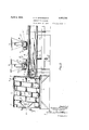
- Fig. 1 is a planviewof a machine in which the-features ofthe invention are incorporat- 50 ed, one of the'hoppers being omitted to better disclose certain details of the construction;
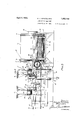
- Fig. 2 is an enlarged fragmentary vertical longitudinal sectional viewtaken on line 2-2 in Fig. 1; i
- Fig. 3 is an enlarged elevational view of a portion of the machine of Fig. 1;
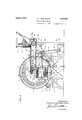
- Fig. 4 is an enlarged vertlcal transverse sectlional view taken on line 4& in 3; an:
- Fig. 5 is a view detailing featnres of one of the. duplicatebranch carrier membersand a hopper for feeding food thereto.
- brackets 12 upon the frame 10 include bear ings which carry shafts 13.
- Each shaft 13 carries spaced apart. discs or rollersli adjacent the ends of the shaft.
- Oppositely disposed discs or rollers 14 are situated beneath the drum at-opposite sidesthereof, and ride in spaced 1 apart circumferential channel members 15, one near each end of the mix ing drum.
- a secondframe 16 includes suitable spaced apart bearings 17 supporting pulleys 18 and 19 upon which a main carrier member or belt 20 is arranged. 'As'shown, the pulley 18 is anidler. and the pulley 19 is adrive pulley.
- the main carrier member or belt 20 is ar ranged adjacent an open end of the mixing drum 11,. and is adapted to travel so that its upper length moves toward said mixing drum.
- the carrier member or belt 20 is for-the purpose of depositing food into the mixing drum, and said drum is adapted to transport the food conveyed to it into ahopper 22 leading from the drum to what may be termed a common mixed food supply.
- the mixing'drum 11 has a spiral 23 upon its interior face for conveying the food fronrthe main carrier member or belt to the hopper 22, and also includes feed plates 24 between the walls of the spiral 23 and extending longitudinally of the mixing drum. Suitable scoop plates 25 are arranged adjacent the drum outlet 26 to insure positive feeding of the food from the mixing drum.
- Means for driving the main carrier member or belt and for rotating the mixing drum includes a drive shaft 27 which protrudes from a transmission case 28.
- the shaft 27 can be driven from any suitable source of power, and the transmission case 28 includes mechanism (not shown) for adjusting the speed of the drive shaft 27 at any desired speed.
- a sprocket 29 upon the drive shaft 27 carries a chain 30 which passes over a sprocket 31 upon a shaft 32 having one of its ends mounted in a frame 49 as at 33, and its other end portion mounted as at 34 in brackets 35 carried by the frame 10.
- the shaft 32 carries a sprocket 36 upon which a chain 37' is arranged.
- the chain 37 passes about a sprocket 38 circumferentially disposed upon the outer face of the mixing drum 11 and secured thereto.
- a bevel gear 39 upon the shaft 32 meshes with an annular bevel gear 40 upon a shaft 41 which fixedly carries the drive pulley 19.
- the portion of the shaft 41 adjacent the annular bevel gear 40 is mounted in a bracket 42 carried by the frame 10.
- the opposite end portion of said shaft 41 is mounted in the bearings 17.
- Each branch carrier member or belt, denoted 44 is situated at one side of the main carrier member or belt, desirably at right angles thereto, and the inner portion of each branch carrier member or belt is disposed directly above the upper length of the main carrier member or belt in position to deposit food thereupon.
- the branch carrier members or belts are all disposed in spaced relation to each other at the same side of the main carrier member or belt, although one or more of the branch carrier members or belts could be disposed at the other side of the main carrier member or belt.
- Each branch carrier member-44 consists of a belt 45 ridable upon spaced apart pulleys 46 and 47 the outer pulley 46 being an idler pulley and the inner pulley 47 being a drive pulley.
- Each idler pulley 46 is carried by a shaft 48 suitably mounted upon the frame 49 which supports the branch carrier members or belts 44, while each drive pulley 47 is fixed to a shaft 50 suitably mounted in brackets 51 upon the frame 49.
- Means for driving the branch carrier members or belts 44 includes a drive shaft 52 protruding from the transmission case 28, the said drive shaft 52 being adjustable as to speed in the same manner as the drive shaft 27.
- a sprocket 53 upon the drive shaft 52 carries a chain 54 which rides over a sprocket 55 upon a shaft 56 mounted upon the frame 49 as at 57.
- the shaft 56 also has a small pulley 58 carrying a belt 59 arranged over a larger pulley 60 fixed upon a short shaft 61 mounted in brackets 62 upon the frame 49.
- the short shaft 61 has small, spaced apart pulleys 63 each of which carries a belt 64, and each belt 64 rides upon a pulley 65 fixed upon a shaft 50.
- branch carrier members or belts 44 may be employed for the purpose of transporting food which has a tendency to stick and to not be easily removed from said branch carrier member or belt to fall to the main carrier member or belt by gravity. In such event, special means is employed to positively remove the food from the branch carrier member or belt.
- numeral 66 represents a rotary brush carried by a shaft 67 suitably mounted in extensions of brackets 51 which carry the shaft 50 of the branch carrier member or belt at the right in Fig. 1.
- a sprocket 68 upon the shaft 56 carries a chain 69 which rides over a sprocket 7 0 upon a shaft 71, mounted in the frame 49.
- the shaft 71 also carries a pulley 72.
- a belt 73 arranged upon the pulley 72 rides over a pulley 74 upon the shaft 67.
- the main carrier member or belt is disposed within an elongated housing, represented generally at 75, constructed to constitute a trough 7 6 above the upper length of the main carrier member or belt for insuring that the food will not be accidentally removed from the main carrier member or belt during its passage to the mixing drum.
- the housing 7 5 is serviceable to keep dirt away from the food which is carried y the main carrier member or belt.
- a hopper 77 for each branch carrier member or belt is situated adjacent the outer end thereof to deposit food upon the belt as it moves ahead.
- each hopper 77 is conveniently supported upon the frame 4:9 as indicated at 78, and includes an adjustable gate 7 9 for regulating the amount of food allowed to pass to the corresponding branch carrier belt as it moves along.
- elevating the gate 79 allows passage of an. increased amount of food, and depressing said gate cuts down the amount of food which can pass to the belt.
- the shafts 48 for the idler pulleys 4&6 are each mounted in blocks 80 slidably adjustable on the frame 4.9 by means of threaded rods 81 having nuts 82 which engage the hopper supports. By adjustment of the nuts upon the rods the idler pulleys 46 are moved inwardly or outwardly to adjust the tension of the branch carrier belts 44:. See Figs. 4 and 5.
- the machine as illustrated and d scribed was designed more particularly for the purpose of mixing the ingredients of vegetable salad. It could, obviously, be employed for a variety of other purposes.
- the chopped-up vegetables are deposited in the hoppers 77, say, for example, a different chopped-up vegetable in each hopper.
- the gates 79 are independently adjusted to allow any desired amounts of the vegetables to progressively pass to the corresponding branch carrier belts as these advance.
- the branch carrier belts move ahead, the food placed thereon from the hoppers is continuously spilled to the main carrier belt, and as the main carrier belt moves ahead and past the several branch carrier belts, the various ingredients of the salad to be made are spread along the main carrier belt in the general proportionin which the different foods are to occur in the salad.
- the food is carried to the mixing drum as the main carrier belt moves ahead, and is advanced by the spiral of the drum to the drum outlet. While in the drum the food becomes mixed, and upon leaving the drum and entering the hopper 22 and passing to the general. mixed food supply, the ingredients of the food are in the proper proportion tobe canned or otherwise disposed of. It being understood that desired or for-other use.
- a food mixing machine comprising a mixing drum for depositing food into a common supply of mixed food, a main carrier member for transporting difierent kinds of foods to said mixing drum, branch carrier members for transporting each dillerent kind of food to constitute said common supply of mixed food to said main carrier member, and means "for positively removing from a branch carrier member food which might otherwise have tendency to stick thereto, and for depositing said tood upon said main carrier member.
- a food mixing machine comprising a mixing drum for depositing food into a common supply of mixed food, a main carrier member for transporting difierent kinds of foods to said mixing drum, branch carrier members for transporting each different kind of food to constitute said common supply of mixed food to said main carrier member, means for independently regulating the amount of food fed by each branch carrier member to said main carrier member, and means for positively removing from a branch carrier member food which might otherwise have tendency to stick thereto, and for depositing said food upon said main carrier member.
- a food mixing machine comprising a mixing drum for continuously depositing food into a common supply of mixed food, a main carrier member for continuously transporting diiferent kinds of foods to said mixing drum, branch carrier members for continuously transporting each of the different kind of foods to constitute said common supply of mixed food to said main carrier memher, and means for positively removing from a branch carrier member food which might otherwise have tendency to stick thereto, and for depositing said food upon said main carrier member.
- a food mixing machine comprising a mixing drum for continuously depositing food into a common supply of mixed food, a main carrier member for continuously transporting different kinds of foods to said mixing drum, branch carrier members for continuously transporting each of the different kinds of foods to constitute said common supply of mixed food to said main carrier member, means ⁇ or independently regulating the amount of food fed to said main carrier member by each branch carrier member, and means for positively removing from a branch carrier member food which might otherwise have tendency to stick thereto, and for depositing said food upon said main carrier member.
Landscapes
- Life Sciences & Earth Sciences (AREA)
- Chemical & Material Sciences (AREA)
- Engineering & Computer Science (AREA)
- Food Science & Technology (AREA)
- Polymers & Plastics (AREA)
- Apparatuses For Bulk Treatment Of Fruits And Vegetables And Apparatuses For Preparing Feeds (AREA)
Description
April 5, 1932. A. F. WENTWORTH 1,352,764-
FOOD MIXING MACHINE Filed March 17, 1930 4 Sheets-Sheet l April 5, A. F. WENTWORTH 1,852,764
FOOD MIXING MACHINE Filed March 17, 1930 4 Shets-Sheet 2 MP W Q ulin A-i-TOBNEY;
April 5, 1932. A. F. WENTWORTH 1,852,764
FOOD MIXING MACHINE Filed March 17, 1930 4 Sheets-Sheet 3 flit 676L 02 AMAZ/AH F7LLMOEE WENTWoeTH L w! M April 5, 1932.
A. F. WENTWORTH FOOD MIXING MACHINE Filed March 17, 1930 4 Sheets-Sheet 4 C v 991a) [raven zar fwgm MM ATTORNEY)" Patented Apr. 5, 1932 UNITED STATES PAT-ear OFFICE .AHLAZIAH FILIIMORE WENTWORTH, OF FAIRMONT, MINNESOTA, ASSIGNOB T FAIR MONTOANNING- COMPANY, OF FAIRMONT, MINNESOTA, A CORPORATION OF MINNIE 'SOTA FOOD MIXING MACHINE ,Applicationfiled March 17, 1930. SeriaI No. 435,514.
llhis invention .rel ateslto a machine for mixingtogether. different foods, such, for ex ample, as different kinds of chopped vegetables -.or fruits to :be used vas vegetable or I, fruit-salad.
The general object of'the invention is to provide :a machine which will be capable of feedingga plurality of different kinds of foods to acommonmixed food supply, and where- 410 in rthezamount of each different kind offood fed to the-common food supply can be any preferred amount to constitute any desired proportion of-the whole mixed food supply.
Aimore specific object-is to-provide a machine which will include a mixing drum adapted to depositfood into a common supply of mixed food, a main carrier member for transportingdifferent kinds of foods to the mixing drum, and branch carrier members for-transporting each different kind ofrfood tozthenrain carrier member.
.-A further specific object is to provide means in the machine for adjustably regulating the: amount of food which can be fed by ,eachbranch carrier,member to the main carrier member, whereby the amount of an individual food or foods fed-to the mixture can constitute any desired proportion of the wholequantityof mixed food. I
,A further specific object is to provide means .in-the machine for positively removing-fromrany ,or all of said branch carrier members food which might otherwise have tendency to stick thereto, and for depositing the -r'foo,d upon the main carrier member.
.Qtherobjeets and advantages of'the invention will become apparent from the full description thereof now to bemade, it being understood that the disclosure herein is merely illustrative and intended in no way in a-limiting sense, changes-in details of construction and arrangement o'fparts'being permissible so long as within the scope of the cl aims which follow. I
In'the accompanying drawings forming a part of this specification,
Fig. 1 is a planviewof a machine in which the-features ofthe invention are incorporat- 50 ed, one of the'hoppers being omitted to better disclose certain details of the construction;
Fig. 2 is an enlarged fragmentary vertical longitudinal sectional viewtaken on line 2-2 in Fig. 1; i
Fig. 3is an enlarged elevational view of a portion of the machine of Fig. 1;
Fig. 4 is an enlarged vertlcal transverse sectlional view taken on line 4& in 3; an:
Fig. 5 is a view detailing featnres of one of the. duplicatebranch carrier membersand a hopper for feeding food thereto.
With respect to the drawings and the nuierals of reference thereon, represents a frame adaptedto be supported upon a floor and in turn rotatably supporting ahorizontally disposed mixing drum 11. As shown, brackets 12 upon the frame 10 include bear ings which carry shafts 13. Each shaft 13 carries spaced apart. discs or rollersli adjacent the ends of the shaft. Oppositely disposed discs or rollers 14 are situated beneath the drum at-opposite sidesthereof, and ride in spaced 1 apart circumferential channel members 15, one near each end of the mix ing drum. V
A secondframe 16includes suitable spaced apart bearings 17 supporting pulleys 18 and 19 upon whicha main carrier member or belt 20 is arranged. 'As'shown, the pulley 18 is anidler. and the pulley 19 is adrive pulley.
The main carrier member or belt 20 is ar ranged adjacent an open end of the mixing drum 11,. and is adapted to travel so that its upper length moves toward said mixing drum. A plate 21, suitably disposed beneath the upper length of the carrier member or belt 20 to support said upper length, is at tached to the frame 16 many convenient manner. p
The carrier member or belt 20 is for-the purpose of depositing food into the mixing drum, and said drum is adapted to transport the food conveyed to it into ahopper 22 leading from the drum to what may be termed a common mixed food supply. As shown more clearly in Figs. 2 and 4, the mixing'drum 11 has a spiral 23 upon its interior face for conveying the food fronrthe main carrier member or belt to the hopper 22, and also includes feed plates 24 between the walls of the spiral 23 and extending longitudinally of the mixing drum. Suitable scoop plates 25 are arranged adjacent the drum outlet 26 to insure positive feeding of the food from the mixing drum.
Means for driving the main carrier member or belt and for rotating the mixing drum includes a drive shaft 27 which protrudes from a transmission case 28. The shaft 27 can be driven from any suitable source of power, and the transmission case 28 includes mechanism (not shown) for adjusting the speed of the drive shaft 27 at any desired speed. A sprocket 29 upon the drive shaft 27 carries a chain 30 which passes over a sprocket 31 upon a shaft 32 having one of its ends mounted in a frame 49 as at 33, and its other end portion mounted as at 34 in brackets 35 carried by the frame 10. The shaft 32 carries a sprocket 36 upon which a chain 37' is arranged. The chain 37 passes about a sprocket 38 circumferentially disposed upon the outer face of the mixing drum 11 and secured thereto. A bevel gear 39 upon the shaft 32 meshes with an annular bevel gear 40 upon a shaft 41 which fixedly carries the drive pulley 19. The portion of the shaft 41 adjacent the annular bevel gear 40 is mounted in a bracket 42 carried by the frame 10. The opposite end portion of said shaft 41 is mounted in the bearings 17.
It will be evident that rotation of the drive shaft 27 will, through the instrumentality of the elements described, cause the mixing drum 11 to revolve upon the discs or rollers 14, and the main carrier member or belt 20 to feed ahead provided said shaft 27 is caused to rotate in the feeding ahead direction of said main carrier member or belt. The arrangement of the discs or rollers 14 in the channel members 15 precludes longitudinal movement of the mixing drum.
Each branch carrier member or belt, denoted 44, is situated at one side of the main carrier member or belt, desirably at right angles thereto, and the inner portion of each branch carrier member or belt is disposed directly above the upper length of the main carrier member or belt in position to deposit food thereupon. As disclosed, the branch carrier members or belts are all disposed in spaced relation to each other at the same side of the main carrier member or belt, although one or more of the branch carrier members or belts could be disposed at the other side of the main carrier member or belt.
Each branch carrier member-44 consists of a belt 45 ridable upon spaced apart pulleys 46 and 47 the outer pulley 46 being an idler pulley and the inner pulley 47 being a drive pulley. Each idler pulley 46 is carried by a shaft 48 suitably mounted upon the frame 49 which supports the branch carrier members or belts 44, while each drive pulley 47 is fixed to a shaft 50 suitably mounted in brackets 51 upon the frame 49.
Means for driving the branch carrier members or belts 44 includes a drive shaft 52 protruding from the transmission case 28, the said drive shaft 52 being adjustable as to speed in the same manner as the drive shaft 27. A sprocket 53 upon the drive shaft 52 carries a chain 54 which rides over a sprocket 55 upon a shaft 56 mounted upon the frame 49 as at 57. The shaft 56 also has a small pulley 58 carrying a belt 59 arranged over a larger pulley 60 fixed upon a short shaft 61 mounted in brackets 62 upon the frame 49. The short shaft 61 has small, spaced apart pulleys 63 each of which carries a belt 64, and each belt 64 rides upon a pulley 65 fixed upon a shaft 50. It will be evident by reference to Figs. 1 and 3 that rotation of the drive shaft 52 in proper direction will, through the instrumentality of the elements just described, cause the two carrier members or belts at the right to move the upper lengths of said branch carrier members or belts toward the main carrier member or belt. As shown more clearly in Fig. 1, the shaft 56 carries a small pulley 58 upon which a belt 59' is arranged, and the belt 59 rides over a pulley 60 secured directly upon the shaft 50 of the branch carrier member or belt at the left to thus drive this carrier member or belt. Any desired number of branch carrier members or belts, greater or less than three as shown, can be employed, and each branch carrier member or belt utilized can be driven in any convenient manner, as from the drive shaft 52.
One or more of the branch carrier members or belts 44 may be employed for the purpose of transporting food which has a tendency to stick and to not be easily removed from said branch carrier member or belt to fall to the main carrier member or belt by gravity. In such event, special means is employed to positively remove the food from the branch carrier member or belt. 'As shown more clearly in Figs. 1, 2 and 4, numeral 66 represents a rotary brush carried by a shaft 67 suitably mounted in extensions of brackets 51 which carry the shaft 50 of the branch carrier member or belt at the right in Fig. 1. A sprocket 68 upon the shaft 56 carries a chain 69 which rides over a sprocket 7 0 upon a shaft 71, mounted in the frame 49. The shaft 71 also carries a pulley 72. A belt 73 arranged upon the pulley 72rides over a pulley 74 upon the shaft 67. Thus, by rotation of the drive shaft 52 to feed the branch carrier members or belts 44 ahead, the rotary brush 66 isdriven in the direction of the arrow of Fig. 4 to Wipe the food for the correspondingbranch carrier member or belt and cause it to be deposited upon the main carrier member or belt. The
caused to move at a more rapid rate of speed than the branch carrier belt to insure that the food will be positively wiped off.
As disclosed, the main carrier member or belt is disposed within an elongated housing, represented generally at 75, constructed to constitute a trough 7 6 above the upper length of the main carrier member or belt for insuring that the food will not be accidentally removed from the main carrier member or belt during its passage to the mixing drum. The housing 7 5 is serviceable to keep dirt away from the food which is carried y the main carrier member or belt.
A hopper 77 for each branch carrier member or belt is situated adjacent the outer end thereof to deposit food upon the belt as it moves ahead. As shown, each hopper 77 is conveniently supported upon the frame 4:9 as indicated at 78, and includes an adjustable gate 7 9 for regulating the amount of food allowed to pass to the corresponding branch carrier belt as it moves along. Obviously, elevating the gate 79 allows passage of an. increased amount of food, and depressing said gate cuts down the amount of food which can pass to the belt.
The shafts 48 for the idler pulleys 4&6 are each mounted in blocks 80 slidably adjustable on the frame 4.9 by means of threaded rods 81 having nuts 82 which engage the hopper supports. By adjustment of the nuts upon the rods the idler pulleys 46 are moved inwardly or outwardly to adjust the tension of the branch carrier belts 44:. See Figs. 4 and 5.
The machine as illustrated and d scribed was designed more particularly for the purpose of mixing the ingredients of vegetable salad. It could, obviously, be employed for a variety of other purposes. In practice, the chopped-up vegetables are deposited in the hoppers 77, say, for example, a different chopped-up vegetable in each hopper. The gates 79 are independently adjusted to allow any desired amounts of the vegetables to progressively pass to the corresponding branch carrier belts as these advance. As the branch carrier belts move ahead, the food placed thereon from the hoppers is continuously spilled to the main carrier belt, and as the main carrier belt moves ahead and past the several branch carrier belts, the various ingredients of the salad to be made are spread along the main carrier belt in the general proportionin which the different foods are to occur in the salad. The food is carried to the mixing drum as the main carrier belt moves ahead, and is advanced by the spiral of the drum to the drum outlet. While in the drum the food becomes mixed, and upon leaving the drum and entering the hopper 22 and passing to the general. mixed food supply, the ingredients of the food are in the proper proportion tobe canned or otherwise disposed of. It being understood that desired or for-other use. I i
' It is assumedthat such a food as pmnento might stick to a branch carrier member or. belt, and the rotary brush 66 is for the pur-- pose of insuring-that a food which isliableto stick will be positively removed from a branch carrier mmeber or belt'and deposited upon the main carrier member or belt.
I claim as my invention:
1. A food mixing machine comprising a mixing drum for depositing food into a common supply of mixed food, a main carrier member for transporting difierent kinds of foods to said mixing drum, branch carrier members for transporting each dillerent kind of food to constitute said common supply of mixed food to said main carrier member, and means "for positively removing from a branch carrier member food which might otherwise have tendency to stick thereto, and for depositing said tood upon said main carrier member.
2. A food mixing machine comprising a mixing drum for depositing food into a common supply of mixed food, a main carrier member for transporting difierent kinds of foods to said mixing drum, branch carrier members for transporting each different kind of food to constitute said common supply of mixed food to said main carrier member, means for independently regulating the amount of food fed by each branch carrier member to said main carrier member, and means for positively removing from a branch carrier member food which might otherwise have tendency to stick thereto, and for depositing said food upon said main carrier member.
3. A food mixing machine comprising a mixing drum for continuously depositing food into a common supply of mixed food, a main carrier member for continuously transporting diiferent kinds of foods to said mixing drum, branch carrier members for continuously transporting each of the different kind of foods to constitute said common supply of mixed food to said main carrier memher, and means for positively removing from a branch carrier member food which might otherwise have tendency to stick thereto, and for depositing said food upon said main carrier member.
4. A food mixing machine comprising a mixing drum for continuously depositing food into a common supply of mixed food, a main carrier member for continuously transporting different kinds of foods to said mixing drum, branch carrier members for continuously transporting each of the different kinds of foods to constitute said common supply of mixed food to said main carrier member, means {or independently regulating the amount of food fed to said main carrier member by each branch carrier member, and means for positively removing from a branch carrier member food which might otherwise have tendency to stick thereto, and for depositing said food upon said main carrier member.
In Witness whereof I have hereunto set my hand this 14th day of March, 1930.
AMAZIAH FILLMORE WENTWORTH.
Priority Applications (1)
| Application Number | Priority Date | Filing Date | Title |
|---|---|---|---|
| US436514A US1852764A (en) | 1930-03-17 | 1930-03-17 | Food mixing machine |
Applications Claiming Priority (1)
| Application Number | Priority Date | Filing Date | Title |
|---|---|---|---|
| US436514A US1852764A (en) | 1930-03-17 | 1930-03-17 | Food mixing machine |
Publications (1)
| Publication Number | Publication Date |
|---|---|
| US1852764A true US1852764A (en) | 1932-04-05 |
Family
ID=23732718
Family Applications (1)
| Application Number | Title | Priority Date | Filing Date |
|---|---|---|---|
| US436514A Expired - Lifetime US1852764A (en) | 1930-03-17 | 1930-03-17 | Food mixing machine |
Country Status (1)
| Country | Link |
|---|---|
| US (1) | US1852764A (en) |
Cited By (3)
| Publication number | Priority date | Publication date | Assignee | Title |
|---|---|---|---|---|
| US2562506A (en) * | 1949-01-31 | 1951-07-31 | Fibreboard Products Inc | Batch mixing apparatus |
| US3228660A (en) * | 1963-11-13 | 1966-01-11 | American Olean Tile Company In | Blending apparatus and method, especially for tiles |
| US6523727B2 (en) | 2000-04-26 | 2003-02-25 | Peerless Machinery Corp. | Dough feeding unit |
-
1930
- 1930-03-17 US US436514A patent/US1852764A/en not_active Expired - Lifetime
Cited By (3)
| Publication number | Priority date | Publication date | Assignee | Title |
|---|---|---|---|---|
| US2562506A (en) * | 1949-01-31 | 1951-07-31 | Fibreboard Products Inc | Batch mixing apparatus |
| US3228660A (en) * | 1963-11-13 | 1966-01-11 | American Olean Tile Company In | Blending apparatus and method, especially for tiles |
| US6523727B2 (en) | 2000-04-26 | 2003-02-25 | Peerless Machinery Corp. | Dough feeding unit |
Similar Documents
| Publication | Publication Date | Title |
|---|---|---|
| US1319190A (en) | van houten | |
| US3404659A (en) | Machine for coating articles with finely divided particles, with conveyors | |
| US2614708A (en) | Cement conveyer | |
| US2704146A (en) | Feeding mechanism for eggs | |
| US2055075A (en) | Can-filling machine | |
| US1852764A (en) | Food mixing machine | |
| US1457352A (en) | Apparatus for conveying and spacing articles | |
| US2683439A (en) | Endless conveyer poultry feeder | |
| US1908539A (en) | Means for coating bakery goods | |
| US3022646A (en) | Machine for continuous cooling of giblets | |
| US2315091A (en) | Loadfr | |
| CN107691542A (en) | An automatic production equipment for small steamed buns | |
| US2705474A (en) | Automatic feeder for poultry and the like | |
| US1679717A (en) | Conveyer | |
| US2547473A (en) | Machine for sizing vegetables | |
| US3417926A (en) | Spreader chain and fan drive assembly | |
| US2021251A (en) | Conveyer apparatus for dough-working machinery | |
| US1664474A (en) | Salting apparatus | |
| US1797112A (en) | Seed broadcaster | |
| US2840236A (en) | Sizing machine | |
| US1514345A (en) | Machine for applying a top coating of comminuted material to confection-coated wafers | |
| US2120169A (en) | Material distributor or spreader | |
| CN109258497B (en) | Feed feeding equipment for livestock and poultry breeding and feeding method thereof | |
| US2155612A (en) | Apparatus for arranging fruit halves | |
| US1645603A (en) | Sand and gravel washer |