US1852760A - Cylinder gauge - Google Patents
Cylinder gauge Download PDFInfo
- Publication number
- US1852760A US1852760A US232183A US23218327A US1852760A US 1852760 A US1852760 A US 1852760A US 232183 A US232183 A US 232183A US 23218327 A US23218327 A US 23218327A US 1852760 A US1852760 A US 1852760A
- Authority
- US
- United States
- Prior art keywords
- cylinder
- block
- face
- face piece
- indicator
- Prior art date
- Legal status (The legal status is an assumption and is not a legal conclusion. Google has not performed a legal analysis and makes no representation as to the accuracy of the status listed.)
- Expired - Lifetime
Links
- 238000003745 diagnosis Methods 0.000 description 1
- 239000011435 rock Substances 0.000 description 1
Images
Classifications
-
- G—PHYSICS
- G01—MEASURING; TESTING
- G01B—MEASURING LENGTH, THICKNESS OR SIMILAR LINEAR DIMENSIONS; MEASURING ANGLES; MEASURING AREAS; MEASURING IRREGULARITIES OF SURFACES OR CONTOURS
- G01B3/00—Measuring instruments characterised by the use of mechanical techniques
- G01B3/22—Feeler-pin gauges, e.g. dial gauges
-
- G—PHYSICS
- G01—MEASURING; TESTING
- G01B—MEASURING LENGTH, THICKNESS OR SIMILAR LINEAR DIMENSIONS; MEASURING ANGLES; MEASURING AREAS; MEASURING IRREGULARITIES OF SURFACES OR CONTOURS
- G01B5/00—Measuring arrangements characterised by the use of mechanical techniques
- G01B5/003—Measuring of motor parts
-
- G—PHYSICS
- G01—MEASURING; TESTING
- G01B—MEASURING LENGTH, THICKNESS OR SIMILAR LINEAR DIMENSIONS; MEASURING ANGLES; MEASURING AREAS; MEASURING IRREGULARITIES OF SURFACES OR CONTOURS
- G01B5/00—Measuring arrangements characterised by the use of mechanical techniques
- G01B5/08—Measuring arrangements characterised by the use of mechanical techniques for measuring diameters
- G01B5/12—Measuring arrangements characterised by the use of mechanical techniques for measuring diameters internal diameters
Definitions
- My present invention contemplates an. in,- strumenty of novel typeby whichthe wear. or ⁇ original ⁇ imperfections of a bore or cylinder may be observed and measured in. what is. methodically av new way. Generally speak--- ing, it may bel saidl to contemplate the-study of the igureofthe wear ori-imperfection on aA geometrica-l basis by whichl its: relation. toV the top.y of the cylinder bloclr or other-parts of an organized machine may be"observed for corrective diagnosis. e n
- I have shown as an illustrative embodiment a device for thispurpose and in connection therewith have indicated somewhat diagrammatically the uses of such a device. Throughout m the specification and drawings. like reference characters are employed to indicatecorresponding ⁇ parts, and in the drawings:
- Fig. l is a View of an instrument in accordance with my invention in position in a fragmentary cylinderblock.
- nf Fig... rita-ve indicated the instrument.
- this cylinder may be consideredfas dia-grammatically indicated in Fig. laV inwhich the diameter vB--B1 is the original diameter ofthe cylinder, while the line C ⁇ -C1 i'sthe major axis ofthe'lower end of thecylindenlthe distance C2C1 representing.; the dii'erencebetween the original bore and the said major axis. This represents the major, depthV of the wear. It will. be understoodthat the plane B-Bl--Cl-G represents one ofV an iniinite number of diametric planes through the cylinderl axis. These give lineal intercepts similar to the-,line B-C1 or the line BC or lines of intermediate disposition and; form according to the character or figure of the wear.
- the wea-r is, aconio sectionl cut by a cto-axial cylindrical intercept and is in form a tapered figure of crescent shape base tapering to a feathered edge.
- the straight edge of the blade 1 is shown as occupying the lin-e Bl-Cl as indicated in Fig. 1a.
- the face piece 2 of the instrument has its flat lower face on the line B--B1 and supported on the flat top face F of the cylinder' block.
- the blade 1 is clamped in a pivot block 3. This is pivotally supported in a'slot Llin the face piece 2 by pivot screws 5.
- the blade is clamped by a hooked member 6 having a beveled face 61 against which the conic 'end of a screw 7 bears.
- the screw has a knurled head 71 and when screwed in draws the hooked member so as to clamp the blade 1 in the block 3 in any desired position'.
- the face piece 2 is further longitudinally undercut as at 21 and carries a multiplying dial indicator 8 of the reciprocating contact type.
- Contact is indicated as at 81 and is actuated by a lever 9 mounted in the under-V cut 21 of theV face piece 2 and fixed at one end in the block 3 to move with said block.
- the lever is ynormally held down by a spring 10 on a stop screw 11. This spring therefore tends to rock the blade 1 from its position shown in dotted lines in Fig. 4 to its position shown in full lines in that figure.
- the dotted line position is one in which it is at right angles to the face piece 2.
- this instrument In utilizing this instrument it is placed in the cylinder bore with its flat lower face bearing on the face F of the cylinder block. It is positioned so that the blade 1 lies in one of the diametric planes of the cylinder axis and the face piece 2 is then pushed so as to bring the straight edge of the blade against the cylinder wall until it has estab- Y lished a definite bearing. In the case shown this bearing will be along the entire side of the cylinder and at a slight angle to th-e axis thereof as explained in connection with Fig. 1a. In case the wear has been in the lower regions of the cylinder the blade will establish contact only in the angular portion.
- I may provide lateral markings as X on the two sides -of the face piece by which the block may be set with reference to the upper end of the cylinder which is usually in true circle.
- the indicator 8 has an adjustable dial so that it may be set at zero with reference to the pointer y. This is usually done with reference to the 90 angle of the blade 1 with the face piece 2 but it may also be used where the line of maximum wear has been determined and it is desirable to note the deviations therefrom of the indicator in successive planes.
- the instrument In general testing, the instrument is usually applied to a cylinder at several points, say of 90 spacing. This would give the general formof the cylinder. If detailed study is desired of any wear that is localized, a mark maybe made on the cylinder face and this wear studied on successive lines of intercept by simply swinging the device so that the edge of the blade sweeps the wall of the cylinder over its worn area.
- a face piece pivoted thereon and having a slideway therein, a straight edge slidably mounted in said slideway, a lock on the block for clamping the straight edge, an indicator on said face piece, and means fcroperatively connecting said block and indicator to transmit the tilting movement of t-he straight edge.
- a device for testing cylinder bores in faced engine blocks comprising a face piece spanning one end of a cylinder in planal coincidence with the cylinder block face. a block pivoted to said face piece, a straight edge carried by said block and presenting a depending portion functioning as a lineally contacting feeler adapted when introduced into the cylinder bore to Contact with any portion of the cylinder wall which may be out of perpendicular with reference to the cylinder block face, a multiplying indicator, and operative connections from Vsaid indicator to said block for Visually indicating rocking movements of said straight edge.
- a face piece disposable at right angles to a cylinder' axis, a block pivotally mounted thereon, a straight edge slidably supported in said block, a multiplying indicator on said face piece having a reciprocating contact and a lever connection between said block and contact.
- a face piece having an undercut lower face and having a vertical slot adjacent one end, a block pivoted in said slot, a feeler carried by said block, an indicator mounted on the upper face of said face piece to occupy a position thereover, said indicator having a depending contact, and a motion transmitting connection mounted in the undercut lower face of said face piece land disposed between said block and said depending contact of the indicator.
- a face piece having a pivotal connection with said face piece, an indicator mounted on said face piece to occupy a position thereover, said indicator having a depending contact, and a motion transmitting connection disposed beneath said face piece and between said block and said depending contact of the indicator.
- a :face piece disposable at right angles to a cylinder axis, a block pivotally mounted thereon, a straight edge slidably supported in said block, a multiplying indicator on said face piece and having a contact, a lever engageable at one end with said contact and Xed at its other end within said block, and a spring active on said lever and normally tending to maintain said straight edge against the wall of the cylinder bore.
- a face piece disposable at right angles to the axis of the bore to be tested and having its lower face longitudinally undercut to provide a recess, a block pivotally mounted on said face piece at one side thereof and disposed in a plane at substantially right angles thereto, a straight edge slidably mounted on said block and disposed for lineal Contact with the wall of the bore to be tested, a manually operable clamp 'for locka face v JAMES Gr.v SISSON.
Landscapes
- Physics & Mathematics (AREA)
- General Physics & Mathematics (AREA)
- A Measuring Device Byusing Mechanical Method (AREA)
Description
April 5, 1932. .1. G. slssoN 1,852,760
CYLINDER GAUGE Filed NOV. 9. 1927 2 Sheets-Sheet l Patented Apr. 5, 1932 UNITED- s'mrasi PATENT" oFF-ice i JAMES Gr. SISSON, OF ATHOLLMASSAGHUSETTS; ASSIGNOR. THE/II., S; `STJAEHRE'IL COM.- PANY, A CORPORATION MASSACHUSETTS, OBGANIZED IN 1929' CYLINDER G UGE The Vobservation and measurementv ofcyline drical bores as in the case of automobile cylinders where inaccuracies or wear are tof be: observed has become a matter of recognized;
importance. Internal gauges of various types are-used in this work, but these are-gen'- erally of point contact type, measuring or indicating distancesbetween opposite peints onr the cylinder wall. -Thepossibility of' ai .43 better understanding; of. cylinder conditions-V have' been suggested, but present,l availabledevices for obtainingV this understanding seemto have been wanting.
Accordingr to the accepted standard.' in.Y en,-1
.' gine production the usual cylinder bleek3is carefully faced and the cylinder bores fin-- ished in true perpendicularity to thatv face or conversely faced' to the cylinder a-Xesa. However, even in production an, anis-may be inclined or if! originally true may beworn to shift the axis as well'as vary the cylinfdricity.
My present invention contemplates an. in,- strumenty of novel typeby whichthe wear. or` original` imperfections of a bore or cylinder may be observed and measured in. what is. methodically av new way. Generally speak-- ing, it may bel saidl to contemplate the-study of the igureofthe wear ori-imperfection on aA geometrica-l basis by whichl its: relation. toV the top.y of the cylinder bloclr or other-parts of an organized machine may be"observed for corrective diagnosis. e n In the accompanying drawings: I have shown as an illustrative embodiment a device for thispurpose and in connection therewith have indicated somewhat diagrammatically the uses of such a device. Throughout m the specification and drawings. like reference characters are employed to indicatecorresponding` parts, and in the drawings:
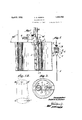
Fig. l is a View of an instrument in accordance with my invention in position in a fragmentary cylinderblock.
1.a, a dagrammaticstudyofV the princ1plesinvo1vedn Fig, l.
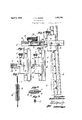
Fig,.12, a. sdevi'ew. of my device removed` l' Eig.; 3l aplanview of: the device. in acylmdera i Eig4`anfenlarged side view ofthedevice partly. broken away.,V
Eig.. 5V af. detaiLof theL blade block assembly. y F1g,..6` a. somewhat similar View indicating the. locking; action.. c
Eig; 7, a section. on the,line7-7', of Figi., 5.. lig a section om the line 8,-- of Fig. 6 all. i
Eig@ a. detail cfa. pivot; screw.V f
nf Fig.. rita-ve indicated the instrument.,
in position, inwhat may be consideredV asa worn cylinder in which the blade isin contactwithf the cylinder Wall in an area. where the wall hasbeen worn te a, slightly conic figure, Its, d'ep arture, fromcylindricity isinf dicated" the; liroken line B-CZ which is parallel with the original cylinder axis and perpendicular to the upper face F ofl the cylind'er block. Inl accordance with the' usual practice,L the face. offthe block` is faced; oi in atrue plane and the cylinders bored on axes.; perpendicular thereto.
The conditionof this cylinder may be consideredfas dia-grammatically indicated in Fig. laV inwhich the diameter vB--B1 is the original diameter ofthe cylinder, while the line C`-C1 i'sthe major axis ofthe'lower end of thecylindenlthe distance C2C1 representing.; the dii'erencebetween the original bore and the said major axis. This represents the major, depthV of the wear. It will. be understoodthat the plane B-Bl--Cl-G represents one ofV an iniinite number of diametric planes through the cylinderl axis. These give lineal intercepts similar to the-,line B-C1 or the line BC or lines of intermediate disposition and; form according to the character or figure of the wear.
In such a figure as shown in la, the wea-r is, aconio sectionl cut by a cto-axial cylindrical intercept and is in form a tapered figure of crescent shape base tapering to a feathered edge. This, of course, is only one of great variety of figures of wear due to a great variety of causes and conditions, but it may be considered as sufficiently indicative of the principles involved.
In the position of the instrument as shown in Fig. 1, the straight edge of the blade 1 is shown as occupying the lin-e Bl-Cl as indicated in Fig. 1a. The face piece 2 of the instrument has its flat lower face on the line B--B1 and supported on the flat top face F of the cylinder' block. The blade 1 is clamped in a pivot block 3. This is pivotally supported in a'slot Llin the face piece 2 by pivot screws 5. In the block 3 the blade is clamped by a hooked member 6 having a beveled face 61 against which the conic 'end of a screw 7 bears. The screw has a knurled head 71 and when screwed in draws the hooked member so as to clamp the blade 1 in the block 3 in any desired position'.`
The face piece 2 is further longitudinally undercut as at 21 and carries a multiplying dial indicator 8 of the reciprocating contact type. Contact is indicated as at 81 and is actuated by a lever 9 mounted in the under-V cut 21 of theV face piece 2 and fixed at one end in the block 3 to move with said block. The lever is ynormally held down by a spring 10 on a stop screw 11. This spring therefore tends to rock the blade 1 from its position shown in dotted lines in Fig. 4 to its position shown in full lines in that figure. The dotted line position is one in which it is at right angles to the face piece 2.
In utilizing this instrument it is placed in the cylinder bore with its flat lower face bearing on the face F of the cylinder block. It is positioned so that the blade 1 lies in one of the diametric planes of the cylinder axis and the face piece 2 is then pushed so as to bring the straight edge of the blade against the cylinder wall until it has estab- Y lished a definite bearing. In the case shown this bearing will be along the entire side of the cylinder and at a slight angle to th-e axis thereof as explained in connection with Fig. 1a. In case the wear has been in the lower regions of the cylinder the blade will establish contact only in the angular portion.
In order to assist in adjusting the facepiece 2 so a to bring the blade 1 in the desired diametric plane, I may provide lateral markings as X on the two sides -of the face piece by which the block may be set with reference to the upper end of the cylinder which is usually in true circle.
These markings serve another purpose which becomes evident in connection with such an instance as that before recited where the wear is below the top of the cylinder. In this case the upper end of the blade will stand in from the edge of the cylinder an amount proportional to the depth of that point below the top of the cylinder where the wear begins; that is to say, the point of angular departure of the wear. For example, if this point of departure was three inches below the upper end of the cylinder then for a given angle of departure the initial line 1 would be offset a certain number of graduations on the scale X from the edge of the cylinder at its upper end. In this way the graduations X not only serve the purpose of getting the face piece 2 in proper diametric position, but serve to indicate the depth of the point of departure so that the location as well as the figure of the wear is shown.
The indicator 8 has an adjustable dial so that it may be set at zero with reference to the pointer y. This is usually done with reference to the 90 angle of the blade 1 with the face piece 2 but it may also be used where the line of maximum wear has been determined and it is desirable to note the deviations therefrom of the indicator in successive planes.
In general testing, the instrument is usually applied to a cylinder at several points, say of 90 spacing. This would give the general formof the cylinder. If detailed study is desired of any wear that is localized, a mark maybe made on the cylinder face and this wear studied on successive lines of intercept by simply swinging the device so that the edge of the blade sweeps the wall of the cylinder over its worn area.
Devices in accordance with my invention may be variously constructed and the device shown may be variously modified, all without departing from the spirit of my invention as defined in the claims which follow.
What I therefore claim and desire to secure by Letters Patent is 1. In a gauge of the class described, a face piece, a block pivoted thereon and having a slideway therein, a straight edge slidably mounted in said slideway, an indicator on said face piece, and means for operatively connecting said block and indicator to transmit the tilting movement of the straight edge.
2. In a gauge of the class described, a face piece, a block pivoted thereon and having a slideway therein, a straight edge slidably mounted in said slideway, a lock on the block for clamping the straight edge, an indicator on said face piece, and means fcroperatively connecting said block and indicator to transmit the tilting movement of t-he straight edge.
3. A device for testing cylinder bores in faced engine blocks, comprising a face piece spanning one end of a cylinder in planal coincidence with the cylinder block face. a block pivoted to said face piece, a straight edge carried by said block and presenting a depending portion functioning as a lineally contacting feeler adapted when introduced into the cylinder bore to Contact with any portion of the cylinder wall which may be out of perpendicular with reference to the cylinder block face, a multiplying indicator, and operative connections from Vsaid indicator to said block for Visually indicating rocking movements of said straight edge.
4. In a device of the class described, a face piece disposable at right angles to a cylinder' axis, a block pivotally mounted thereon, a straight edge slidably supported in said block, a multiplying indicator on said face piece having a reciprocating contact and a lever connection between said block and contact.
5. In a gauge of the class described, piece, a block pivoted thereto, a feeler mounted on said block at one side thereof, an indicator mounted on said face piece to occupy a position thereover, said indicator having a depending contact, and a motion tran-smitting connection disposed beneath said face piece and between said block and said depending Contact of the indicator.V
6. In a gauge of the class described, a face piece having an undercut lower face and having a vertical slot adjacent one end, a block pivoted in said slot, a feeler carried by said block, an indicator mounted on the upper face of said face piece to occupy a position thereover, said indicator having a depending contact, and a motion transmitting connection mounted in the undercut lower face of said face piece land disposed between said block and said depending contact of the indicator.
7. In a gauge of the class described, a face piece, a feeler having a pivotal connection with said face piece, an indicator mounted on said face piece to occupy a position thereover, said indicator having a depending contact, and a motion transmitting connection disposed beneath said face piece and between said block and said depending contact of the indicator.
8. In a. device of the class described, a :face piece disposable at right angles to a cylinder axis, a block pivotally mounted thereon, a straight edge slidably supported in said block, a multiplying indicator on said face piece and having a contact, a lever engageable at one end with said contact and Xed at its other end within said block, and a spring active on said lever and normally tending to maintain said straight edge against the wall of the cylinder bore.
9. In a bore testing device, a face piece disposable at right angles to the axis of the bore to be tested and having its lower face longitudinally undercut to provide a recess, a block pivotally mounted on said face piece at one side thereof and disposed in a plane at substantially right angles thereto, a straight edge slidably mounted on said block and disposed for lineal Contact with the wall of the bore to be tested, a manually operable clamp 'for locka face v JAMES Gr.v SISSON.
Priority Applications (1)
| Application Number | Priority Date | Filing Date | Title |
|---|---|---|---|
| US232183A US1852760A (en) | 1927-11-09 | 1927-11-09 | Cylinder gauge |
Applications Claiming Priority (1)
| Application Number | Priority Date | Filing Date | Title |
|---|---|---|---|
| US232183A US1852760A (en) | 1927-11-09 | 1927-11-09 | Cylinder gauge |
Publications (1)
| Publication Number | Publication Date |
|---|---|
| US1852760A true US1852760A (en) | 1932-04-05 |
Family
ID=22872172
Family Applications (1)
| Application Number | Title | Priority Date | Filing Date |
|---|---|---|---|
| US232183A Expired - Lifetime US1852760A (en) | 1927-11-09 | 1927-11-09 | Cylinder gauge |
Country Status (1)
| Country | Link |
|---|---|
| US (1) | US1852760A (en) |
Cited By (7)
| Publication number | Priority date | Publication date | Assignee | Title |
|---|---|---|---|---|
| US2527758A (en) * | 1946-12-10 | 1950-10-31 | John E Oslund | Die gauge |
| US2706338A (en) * | 1950-06-02 | 1955-04-19 | Ackerman Charles | Gauge |
| US3114978A (en) * | 1960-06-07 | 1963-12-24 | Porter Edward | Internal bore measuring apparatus |
| US3162953A (en) * | 1962-02-16 | 1964-12-29 | Porter Edward | Internal bore measuring apparatus |
| US4638566A (en) * | 1985-03-27 | 1987-01-27 | The Boeing Company | Hole angularity gauge |
| US4897928A (en) * | 1988-06-29 | 1990-02-06 | The Boeing Company | Hole angularity gauge |
| US5133135A (en) * | 1990-12-28 | 1992-07-28 | Susan M. Durfee | Angle gauge |
-
1927
- 1927-11-09 US US232183A patent/US1852760A/en not_active Expired - Lifetime
Cited By (7)
| Publication number | Priority date | Publication date | Assignee | Title |
|---|---|---|---|---|
| US2527758A (en) * | 1946-12-10 | 1950-10-31 | John E Oslund | Die gauge |
| US2706338A (en) * | 1950-06-02 | 1955-04-19 | Ackerman Charles | Gauge |
| US3114978A (en) * | 1960-06-07 | 1963-12-24 | Porter Edward | Internal bore measuring apparatus |
| US3162953A (en) * | 1962-02-16 | 1964-12-29 | Porter Edward | Internal bore measuring apparatus |
| US4638566A (en) * | 1985-03-27 | 1987-01-27 | The Boeing Company | Hole angularity gauge |
| US4897928A (en) * | 1988-06-29 | 1990-02-06 | The Boeing Company | Hole angularity gauge |
| US5133135A (en) * | 1990-12-28 | 1992-07-28 | Susan M. Durfee | Angle gauge |
Similar Documents
| Publication | Publication Date | Title |
|---|---|---|
| US2693033A (en) | Instrument for checking the distance between holes of different diameters | |
| US1852760A (en) | Cylinder gauge | |
| US3745661A (en) | Brake gauge for measuring brake drums and brake disc rotors | |
| US3939569A (en) | Inspection tool or device | |
| US2388582A (en) | Method of and apparatus for measuring center spacing | |
| CN107990805B (en) | Engine link length, curvature, torsion resistance detection device and detection method | |
| US1459381A (en) | Spirit level | |
| US968884A (en) | Indicating surface-gage. | |
| US2210561A (en) | Outer taper gauge | |
| US2702946A (en) | Dial bore gauge | |
| US4630377A (en) | Valve seat runout gage | |
| US1660986A (en) | Gauge | |
| US1258597A (en) | Universal clinometer. | |
| US1379253A (en) | Combination-gage | |
| US548329A (en) | Key-seat rule | |
| US3507048A (en) | Brake adjusting gage | |
| US2657470A (en) | Presetting device for boring tools | |
| US2609610A (en) | Gauge for roll crowns | |
| US3271871A (en) | Testing instrument | |
| US1842502A (en) | Dial indicator | |
| US1617005A (en) | Outside cylinder gauge | |
| US1575797A (en) | Connecting-rod jig | |
| US1965131A (en) | Alignment gauge | |
| US1505313A (en) | Recording gauge | |
| US2024021A (en) | Dial plug gauge |