US1852753A - Telegraph signal distributing device - Google Patents
Telegraph signal distributing device Download PDFInfo
- Publication number
- US1852753A US1852753A US484842A US48484230A US1852753A US 1852753 A US1852753 A US 1852753A US 484842 A US484842 A US 484842A US 48484230 A US48484230 A US 48484230A US 1852753 A US1852753 A US 1852753A
- Authority
- US
- United States
- Prior art keywords
- segments
- ring
- brush
- distributing device
- bars
- Prior art date
- Legal status (The legal status is an assumption and is not a legal conclusion. Google has not performed a legal analysis and makes no representation as to the accuracy of the status listed.)
- Expired - Lifetime
Links
- 230000005540 biological transmission Effects 0.000 description 1
- 230000011664 signaling Effects 0.000 description 1
Images
Classifications
-
- H—ELECTRICITY
- H04—ELECTRIC COMMUNICATION TECHNIQUE
- H04L—TRANSMISSION OF DIGITAL INFORMATION, e.g. TELEGRAPHIC COMMUNICATION
- H04L13/00—Details of the apparatus or circuits covered by groups H04L15/00 or H04L17/00
- H04L13/02—Details not particular to receiver or transmitter
- H04L13/10—Distributors
Definitions
- This invention relates to impulse transmitting devices and more particularly to rotary distributing devices employed in high speed signaling systems.
- An object of the invention is to increase the number of transmission channels that can be employed over a rotary distributor of a given diameter.
- rotary distributors employed in multiplex telegraph systems have been equipped with rings comprised of segments, some of which were detachable and others formed as integral parts of the rings.
- the segments of the latter group may be made to have an angular length as small as 13 but those which are detachable, in order that they might be conveniently handled, are made considerably longer, say approximately 4 for mechanical reasons. Is is obvious then that the angular length of detachable segments is an important factor in determining the diameter of a distributor.
- the angular length of a detachable segment which may be so reduced that the resistance of the segment to vibration when engaging a contacting brush, and the duration of the transmitted or distributed impulse are the only factors which determine the number of segments that may be arranged in a ring of a given diameter.
- the duration of the transmitted impulse may be made very short when the segments are used in conjunction with storing vacuum tubes.
- the detachable segments may have angular length of about and still have sufiicient stiffness to resist vibration. These segments consist of narrow conducting bars respectively extending at one end between narrow segments formed integrally with a ring in engageable relation with a contacting brush and at the other end to supporting blocks mounted on an extra ring not in engagement with the brush.
- the bars are insulated, preferably by air,
- a segmented ring of a given diameter may be made up of detachable segments of about in angular length and of segments,
- a feature of the lnvention is to provide a ring arranged to transmit over a greater number of channels than could be had if the detachable segments were l in length as heretofore required.
- Another feature is to provide a ring arranged to transmit over a given number of channels and made of considerably smaller diameter than one in which the detachable segments were A 1n diameter even though an extra ring is required.
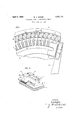
- Fig. 1 illustrates a fragmentary plan view of a rotary distributor equipped with segments arranged in accordance with the present invention
- Fig. 2 shows a perspective view of the manner in which the segments of short angular lengths are mounted on the distributor.
- FIG. 1 fragmentary ring 11 i and continuous ring 12 are shown in an engageable relation with brush 13 which is fixedly mounted on the rotating brush arm 14. concentrically arranged with rings 11,
- segment bars 20 which may be securely fastened at one end to the supporting segments 18, the other end extending between the segments 17 of ring 11.
- the segment bars 20 are positioned wit-h respect to segments 17 to be insulated therefrom by air gaps and from ring 11 by air gaps to form with the segments 17 a substantially continuous metallic path for brush 18, the air gap provided on both sides of each bar being narrow.
- the segments formed by bars 20 may be made to have an angular length of about f which is suflicient to resist being set into vibration when the segments are engaged by the rotating brush.
- Fig. 2 shows one way of mounting the segment bars 20 whereby the bars are, held firmly in slots provided in the supporting segments 18 by means of screws 21.
- other means of mounting bars 20 may be employed, as for example, it is obvious that the screws 21 may be eliminated by Wedging the bars: in the slots. It will be noted in this figure that the air gap entirely surrounds each of the bars 20 at that portion which lies within the ring 11.
- a rotary device for distributing electrical impulses comprising a pair of rings, a brush for interconnecting said rings, segments integrally formed on one of said rings, a third ring, and segments on said third ring, a conducting element being securely fastened to each of the segments on said third ring and projecting insulatively between the adjacent segments on the first mentioned segmented ring to be in engageable relation with said brush.
- a rotary device for distributing electrical impulses comprising a pair of rings, a brush for interconnecting said rings, seg ments integrally formed on one of said rings, a third ring, segments on said third ring and a conducting element securely fastened to each of said segments on said third ring and projected between adjacent segments of the first mentioned segmented ring, said elements being in engageable relation with said brush and insulated by air gaps from the segments of the first mentioned segmented ring.
- each of the conducting elements within the portion in engageable relation with the brush is of sufficient; angular length as compared to its radial length as not to vibrate when engaged by the brush.
Landscapes
- Engineering & Computer Science (AREA)
- Computer Networks & Wireless Communication (AREA)
- Signal Processing (AREA)
- Apparatus For Radiation Diagnosis (AREA)
Description
April 5, 1932. w, KNQQP 1 852fi53 TELEGRAPH SIGNAL DISTRIBUTING DEVICE Filed Sept. 27, 1930 FIG. m
w w /5 w 7 w lNVENTOR BY I A ATTORNEY Patented Apr. 5, 1932 UNITED STATES PATENT OFFIQE WILLIAM A. KNOOP, F HEMPSTEAD, NEW YORK, ASSIGNOR TO BELL TELEPHONE T" LABORATORIES, INCORPORATED, OF NEW YORK, N. Y., A CORPORATION OF NEW YORK TELEGRAPH SIGNAL DISTRIBUTING DEVICE Application filed September 27, 1930.
This invention relates to impulse transmitting devices and more particularly to rotary distributing devices employed in high speed signaling systems.
5 An object of the invention is to increase the number of transmission channels that can be employed over a rotary distributor of a given diameter.
Heretofore, rotary distributors employed in multiplex telegraph systems have been equipped with rings comprised of segments, some of which were detachable and others formed as integral parts of the rings. The segments of the latter group may be made to have an angular length as small as 13 but those which are detachable, in order that they might be conveniently handled, are made considerably longer, say approximately 4 for mechanical reasons. Is is obvious then that the angular length of detachable segments is an important factor in determining the diameter of a distributor.
According to the present invention, the angular length of a detachable segment, which may be so reduced that the resistance of the segment to vibration when engaging a contacting brush, and the duration of the transmitted or distributed impulse are the only factors which determine the number of segments that may be arranged in a ring of a given diameter. The duration of the transmitted impulse may be made very short when the segments are used in conjunction with storing vacuum tubes. The detachable segments may have angular length of about and still have sufiicient stiffness to resist vibration. These segments consist of narrow conducting bars respectively extending at one end between narrow segments formed integrally with a ring in engageable relation with a contacting brush and at the other end to supporting blocks mounted on an extra ring not in engagement with the brush.
The bars are insulated, preferably by air,
from the segments integrally formed and may be detachably or fixedly mounted, as desired, on the supporting blocks. In this way, a segmented ring of a given diameter may be made up of detachable segments of about in angular length and of segments,
Serial No. 484,842.
integrally formed, of about in angular length.
A feature of the lnvention is to provide a ring arranged to transmit over a greater number of channels than could be had if the detachable segments were l in length as heretofore required.
Another feature is to provide a ring arranged to transmit over a given number of channels and made of considerably smaller diameter than one in which the detachable segments were A 1n diameter even though an extra ring is required.
Other objects and features will be found in the following description and appended claims when taken in conjunction with the accompanying drawings of which:
Fig. 1 illustrates a fragmentary plan view of a rotary distributor equipped with segments arranged in accordance with the present invention; and
Fig. 2 shows a perspective view of the manner in which the segments of short angular lengths are mounted on the distributor.
Referring to Fig. 1 fragmentary ring 11 i and continuous ring 12 are shown in an engageable relation with brush 13 which is fixedly mounted on the rotating brush arm 14. concentrically arranged with rings 11,
provided with segments 18 detachably mounted thereon by means of screws 19. Segments 18 support the segment bars 20 which may be securely fastened at one end to the supporting segments 18, the other end extending between the segments 17 of ring 11. The segment bars 20 are positioned wit-h respect to segments 17 to be insulated therefrom by air gaps and from ring 11 by air gaps to form with the segments 17 a substantially continuous metallic path for brush 18, the air gap provided on both sides of each bar being narrow. In this way the segments formed by bars 20 may be made to have an angular length of about f which is suflicient to resist being set into vibration when the segments are engaged by the rotating brush.
Fig. 2 shows one way of mounting the segment bars 20 whereby the bars are, held firmly in slots provided in the supporting segments 18 by means of screws 21. However, other means of mounting bars 20 may be employed, as for example, it is obvious that the screws 21 may be eliminated by Wedging the bars: in the slots. It will be noted in this figure that the air gap entirely surrounds each of the bars 20 at that portion which lies within the ring 11.
What is claimed is:
1. A rotary device for distributing electrical impulses comprising a pair of rings, a brush for interconnecting said rings, segments integrally formed on one of said rings, a third ring, and segments on said third ring, a conducting element being securely fastened to each of the segments on said third ring and projecting insulatively between the adjacent segments on the first mentioned segmented ring to be in engageable relation with said brush.
2. A rotary device for distributing electrical impulses, comprising a pair of rings, a brush for interconnecting said rings, seg ments integrally formed on one of said rings, a third ring, segments on said third ring and a conducting element securely fastened to each of said segments on said third ring and projected between adjacent segments of the first mentioned segmented ring, said elements being in engageable relation with said brush and insulated by air gaps from the segments of the first mentioned segmented ring.
3. A rotary device in accordance with claim 2 wherein each of the conducting elements within the portion in engageable relation with the brush is of sufficient; angular length as compared to its radial length as not to vibrate when engaged by the brush.
In witness whereof, I hereunto subscribe my name this 26th day of September, 1930.
WILLIAM A. KN OOP.
Priority Applications (1)
| Application Number | Priority Date | Filing Date | Title |
|---|---|---|---|
| US484842A US1852753A (en) | 1930-09-27 | 1930-09-27 | Telegraph signal distributing device |
Applications Claiming Priority (1)
| Application Number | Priority Date | Filing Date | Title |
|---|---|---|---|
| US484842A US1852753A (en) | 1930-09-27 | 1930-09-27 | Telegraph signal distributing device |
Publications (1)
| Publication Number | Publication Date |
|---|---|
| US1852753A true US1852753A (en) | 1932-04-05 |
Family
ID=23925846
Family Applications (1)
| Application Number | Title | Priority Date | Filing Date |
|---|---|---|---|
| US484842A Expired - Lifetime US1852753A (en) | 1930-09-27 | 1930-09-27 | Telegraph signal distributing device |
Country Status (1)
| Country | Link |
|---|---|
| US (1) | US1852753A (en) |
Cited By (2)
| Publication number | Priority date | Publication date | Assignee | Title |
|---|---|---|---|---|
| US3086091A (en) * | 1959-05-05 | 1963-04-16 | A R & T Electronics Inc | Shielded switch device |
| US3112377A (en) * | 1956-11-30 | 1963-11-26 | Philips Corp | Bi-directional step-by-step relay |
-
1930
- 1930-09-27 US US484842A patent/US1852753A/en not_active Expired - Lifetime
Cited By (2)
| Publication number | Priority date | Publication date | Assignee | Title |
|---|---|---|---|---|
| US3112377A (en) * | 1956-11-30 | 1963-11-26 | Philips Corp | Bi-directional step-by-step relay |
| US3086091A (en) * | 1959-05-05 | 1963-04-16 | A R & T Electronics Inc | Shielded switch device |
Similar Documents
| Publication | Publication Date | Title |
|---|---|---|
| US2512038A (en) | Error detecting code system | |
| US2534690A (en) | Tube support | |
| US1852753A (en) | Telegraph signal distributing device | |
| US2666196A (en) | Frequency station calling system using bifurcated piezoelectric elements | |
| US3274368A (en) | Laminated distributor brush | |
| US2852628A (en) | Commutator device | |
| US1813913A (en) | Rotary distributor | |
| US1752485A (en) | Secrecy system | |
| US977462A (en) | Means for effecting telephonic communication without connecting-wires. | |
| US1969005A (en) | Apparatus for the directional transmission and reception of wave energy | |
| US2000715A (en) | High speed commutator | |
| IE38253B1 (en) | Improvements in data transmission systems | |
| US2100518A (en) | Impulse sender mechanism | |
| US401067A (en) | Circuit-connecting device | |
| US2865995A (en) | Start-stop distributor ring | |
| US758598A (en) | Transmission of electrical impulses. | |
| US1873429A (en) | Electric current distributing device | |
| US1375728A (en) | Distributing apparatus | |
| US4177486A (en) | Facsimile device | |
| US1897047A (en) | Frequency discrimination signaling system | |
| US2794852A (en) | Multiplex distributor | |
| US1790150A (en) | Means of phasing | |
| US1037330A (en) | Signaling system. | |
| US1957502A (en) | Multiplex telegraph system | |
| US1555041A (en) | Distortion-measuring system |