US1852750A - Cleaning or plating tank - Google Patents
Cleaning or plating tank Download PDFInfo
- Publication number
- US1852750A US1852750A US567683A US56768331A US1852750A US 1852750 A US1852750 A US 1852750A US 567683 A US567683 A US 567683A US 56768331 A US56768331 A US 56768331A US 1852750 A US1852750 A US 1852750A
- Authority
- US
- United States
- Prior art keywords
- tank
- members
- cleaning
- steam
- lining
- Prior art date
- Legal status (The legal status is an assumption and is not a legal conclusion. Google has not performed a legal analysis and makes no representation as to the accuracy of the status listed.)
- Expired - Lifetime
Links
- 238000004140 cleaning Methods 0.000 title description 17
- 238000007747 plating Methods 0.000 title description 11
- 239000002184 metal Substances 0.000 description 12
- 229910052751 metal Inorganic materials 0.000 description 12
- XEEYBQQBJWHFJM-UHFFFAOYSA-N Iron Chemical compound [Fe] XEEYBQQBJWHFJM-UHFFFAOYSA-N 0.000 description 9
- 229910052742 iron Inorganic materials 0.000 description 4
- 238000010276 construction Methods 0.000 description 3
- 238000005554 pickling Methods 0.000 description 3
- XLYOFNOQVPJJNP-UHFFFAOYSA-N water Substances O XLYOFNOQVPJJNP-UHFFFAOYSA-N 0.000 description 2
- 238000003466 welding Methods 0.000 description 2
- 229910000831 Steel Inorganic materials 0.000 description 1
- 230000007547 defect Effects 0.000 description 1
- 238000010438 heat treatment Methods 0.000 description 1
- 238000000034 method Methods 0.000 description 1
- 230000003014 reinforcing effect Effects 0.000 description 1
- 239000010959 steel Substances 0.000 description 1
Images

Classifications
-
- C—CHEMISTRY; METALLURGY
- C23—COATING METALLIC MATERIAL; COATING MATERIAL WITH METALLIC MATERIAL; CHEMICAL SURFACE TREATMENT; DIFFUSION TREATMENT OF METALLIC MATERIAL; COATING BY VACUUM EVAPORATION, BY SPUTTERING, BY ION IMPLANTATION OR BY CHEMICAL VAPOUR DEPOSITION, IN GENERAL; INHIBITING CORROSION OF METALLIC MATERIAL OR INCRUSTATION IN GENERAL
- C23G—CLEANING OR DE-GREASING OF METALLIC MATERIAL BY CHEMICAL METHODS OTHER THAN ELECTROLYSIS
- C23G3/00—Apparatus for cleaning or pickling metallic material
Definitions
- l0 represents the upper and larger U-shaped sheet iron member which forms a bottom 11 and two side portions 12-12 of the upper or cleaning tank 13.
- 14 represents a similar U-shaped sheet iron section which is preferably not as deep as the upper section though is the same length and breadth. It comprises a bottom 15 and parallel side members 16-16,
Landscapes
- Chemical & Material Sciences (AREA)
- Chemical Kinetics & Catalysis (AREA)
- General Chemical & Material Sciences (AREA)
- Engineering & Computer Science (AREA)
- Materials Engineering (AREA)
- Mechanical Engineering (AREA)
- Metallurgy (AREA)
- Organic Chemistry (AREA)
- Cleaning And De-Greasing Of Metallic Materials By Chemical Methods (AREA)
Description
April 5, 1932.
E. A. HOOPER CLEANING OR4 PLATING TANK 2 Sheets-Sheet FiledvOCt. 8, 1931 IN VEN TOR.
A TTORNE YS.
Filed Oct. 8, 1931 2 Sheets-Sheet 9 0 e M mw we. W y u@ l. E mm w 6 ATTORNEYS.
Patented Apr. 5, 1932 UNITED STATES PATENT OFFICE ELMER A. HOOPER, F BRIDGEPORT, CONNECTICUT, ASSIGNOR TO THE MCCATHRON BOILER WORKS CO., OF BRIDGEPORT, CONNECTICUT, A CORPORATION 0F CONNECTI- CUT CLEANING OR PLATING TANK Application led October 8, 1931. Serial No. 567,683.
This invention relates to new and useful improvements in metal cleaning, plating andv pickling tanks such as are used in the metal industry in the process of finishing metal articles. The invention more especially relates to tanks for the above purpose, which are adapted to be heated so as to provide a hot cleaning, plating or pickling solution.
The invention resides in the novel construction of a seamless, rivetless steam acketed tank for the above purpose adapted to be constructed of relatively few sheets of suit-l able fabricated iron, the adjoining edges of which are finished and electrically welded 1n a way to form a seamless, rivetless steam `jacketed tank; also to provide reinforcing threaded stay bolts in the heating chamber so as to prevent the spaced-apart bottom walls thereof from spreading or becoming distorted.
of a relatively thin sheet metal lining such as lead for the plating tank, which is preferably positioned above the steam chest, and further to provide a dra-in from between the walls of the plating tank and its sheetmetal lining, so that in casekthe latter becomes punctured, wears throughL or otherwise leaks, the said defect will immediately become apparent by the escape of water or steam from beneath the lining.
With these and other objects in view, the invention resides and consists in the construction and novel combination and arrangement of parts hereinafter more` fully described, illustrated in theA accompanying drawings, and pointed out in the claims hercto appended, it being understood that various changes in the form, proportion, size, and minor details of construction within the scope lof the claims may be resorted to without departure from the spirit, or sacrificing any of the advantages of the invention.
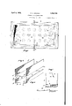
Similar characters of reference denote like or corresponding parts throughout the several figures of the accompanying drawings forming a part of this specification and upon which Fig. l shows a top plan view of my improved metal cleaning or pickling tank;
Fig. 2 is a vertical longitudinal section taken on line 2 of Fig. 1;
Fig. 3 is a vertical cross section taken on line 3-3 of Fig. 1;
Fig. 4 is an enlarged sectional view showing one of the two longitudinal connecting edge portions of the two U-shaped members of the tank;
Fig. 5 shows a perspective view of the upper and larger U-shaped tank member;
Fig. 6 shows a perspective view of the lower U-shape'd member and for forming the steam chest; and
Fig. 7 shows one of the two end plates which are electrically welded to the ends of the two U-shaped members, when positioned one upon the other.
My improved cleaning tank is formed of four main sheet iron parts, a sheet lead lining, a series of braces, and a series of stay bolts, all of which are assembled inthe manner illustrated in the drawings to form two separate compartments, one above the other. The upper and larger one forms the cleaning or plating tank and the lower one the steam chest. A suitable electrolytic, or other solution, according to the particular class of work to be treated is contained within the upper tank, while steam or other means is employed in the lower chest and whereby the solution in the upper tank is heated.
Referring in detail to the characters of reference marked upon the drawings, l0 represents the upper and larger U-shaped sheet iron member which forms a bottom 11 and two side portions 12-12 of the upper or cleaning tank 13. 14 represents a similar U-shaped sheet iron section which is preferably not as deep as the upper section though is the same length and breadth. It comprises a bottom 15 and parallel side members 16-16,
the upper longitudinal edges of which are beveled as indicated b 17, see Figs. 4 and 6. In the assembling o the tank, the upper section 10 is positioned on the lower section by aligning and positioning the lower longitudinal corners of the upper section upon the inner top edgesof the lower member, as illustrated in Fig. 4. The ends of the two members 10 and 14 are thus also positioned in alignment so that the end plates 18-18 may be positioned against the ends in a way to enclose the same. In this connection it will be seen that the edges of the two ends of the bottom member are beveled in slightly as at 19 to receive the correspondingly beveled edge portions 20 and 21 of the end plates; whereas the edges 22 of the ends of the sides 12-12 of the top member 10 are similarly beveled to likewise accommodate the beveled edges 21 of the end plates 18; whereas the edges 23 of the ends of the bottom of said top member are cut straight, to tit against the inner face of the end plates 18, see Fig. 2.
In assembling the structure I first secure the end plates 18-18 to the ends of the top member 10 in a way to close the said ends and form of the three members, the plating tank 10, the said members being secured together by electrically welding all joints between the three members, as indicated by the several welds 24, as for instance, the horizontal and vertical welds between the ends of the bottom and inner face of the end plates by employing a welding rod which electrically welds the two members together and forms a corner filling 24 around the ends of the upper tank and a similar filling 25 across the y under side of the bottom of the top member and against the inner face of the end plate. These three members 10, 18-18, having been assembled as described, braces 26 of which there may be any desired number are next electrically welded to the under side of the bottom 11 of the tank and to the inner face of the end members as is clearly shown in Figs. 1, 2 and 3, and indicated by 35.
The bottom U-shaped sheet iron member 15 is next placed in position upon the bottom member and between the edge portions of the end plates whereby the abutting beveled edges on the said members are electrically welded to form the steam chamber or steam chest 27 beneath the cleaning tank.l This chest is provided with a steam inlet pipe 28 and an outlet pipe 29, each of which may be provided with suitable valves, not shown, to
regulate the flow of steam through the chest..
I series of stay bolts 32 which are positioned and welded in tapped holes of the two bottom a closed seeam chest beneath, a
A pipe connection 34 is provided in the wall of the tank to the space between the wall and lining, as a means of detecting and locating leaks in the lead lining, and whereby any solution that leaks through the lining will run out of the pipe and thus indicat-e that a leak exists. VVhereupon the tank is emptied and water supplied through the said pipe 34 under pressure, which finds its way between the lead lining and steel tank and comes through any holes that; are present in the lead.
Having thus described my invention, what I claim and desire to secure by Letters Patent is 1. A cleaning tank formed of two U-shaped sheet metal members positioned one upon the other with their bottoms in spaced relation to each other and welded together along their adjoining edges, plates welded to and enclosing the ends of the two members in a manner to form an upper cleaning tank and a closed steam chest beneath, a metal lining within the plating tank, and an outlet pipe extending through the wall of the tank from the space between said wall and the lining.
2. A cleaning tank formed of two U-shaped sheet metal members positioned one upon the other with their bottoms in spaced relation to each other and welded together along the adjoining edges, plates welded to and enclosing the adjacent ends of the two members in a manner to form an upper cleanin tank and ange surrounding the top edge of the tank, a sheet metal lining within the plating tank and extended up and over said langed top edge, and an outlet pipe extendinor through the wall of the tank from the spacelbetween said wall and lining.
3. A seamless, rivetless steam j acketed cleaning tank formed of two U-shaped sheet metal members positioned one upon the other with their bottoms in spaced relation to each other and welded together along their adjoining edges, plates welded to and enclosing the adjacent ends of the two members in a manner to form an upper cleaning tank and a closed steam chest beneath, the edges of the ends of said U-shaped members being beveled, plates, one for each end, having beveled edges to engage the beveled edges of the U-shaped members to enclose the ends of the tank and steam chest, the said adjoining edlge portions of the members being electrica y welded.
4. A seamless, rivetless steam jacketed cleaning tank formed of U-shaped sheet metal members positioned one upon the other with their bottomsl in spaced relation and welded together along the adjoining edges, plates welded to and enclosing the two ends of said members in a manner to form an upper cleaning tank and a closed steam chest beneath, brace plates secured to the bottoms of one of the said U-shaped members and end members, and stay bolts secured in the bottom of the said U-shaped members to hold them in spaced relation.
Signed at Bridgeport,l in the county of Fairfield and State of Connecticut, this 2nd day of October, A. D. 1931.
,2o ELMER A. HOOPER.
Priority Applications (1)
| Application Number | Priority Date | Filing Date | Title |
|---|---|---|---|
| US567683A US1852750A (en) | 1931-10-08 | 1931-10-08 | Cleaning or plating tank |
Applications Claiming Priority (1)
| Application Number | Priority Date | Filing Date | Title |
|---|---|---|---|
| US567683A US1852750A (en) | 1931-10-08 | 1931-10-08 | Cleaning or plating tank |
Publications (1)
| Publication Number | Publication Date |
|---|---|
| US1852750A true US1852750A (en) | 1932-04-05 |
Family
ID=24268206
Family Applications (1)
| Application Number | Title | Priority Date | Filing Date |
|---|---|---|---|
| US567683A Expired - Lifetime US1852750A (en) | 1931-10-08 | 1931-10-08 | Cleaning or plating tank |
Country Status (1)
| Country | Link |
|---|---|
| US (1) | US1852750A (en) |
-
1931
- 1931-10-08 US US567683A patent/US1852750A/en not_active Expired - Lifetime
Similar Documents
| Publication | Publication Date | Title |
|---|---|---|
| US1852750A (en) | Cleaning or plating tank | |
| US2092490A (en) | Alloy lined vessel | |
| US1842735A (en) | Tank construction | |
| US2043694A (en) | Laminated metal barrel | |
| US4190038A (en) | Solar heater | |
| US1290093A (en) | Ship construction. | |
| US1595633A (en) | Compartment-tank construction | |
| US2076207A (en) | Distortion check for welding apparatus | |
| US1521255A (en) | Multiple-compartment tank | |
| US2329674A (en) | Degreasing apparatus | |
| IT201800007924A1 (en) | Tank with spiral heat exchange pocket | |
| US2023461A (en) | Float structure | |
| US2061429A (en) | Heat exchange apparatus | |
| US2146180A (en) | Plank for covering hatches and other openings | |
| US942014A (en) | Bar-fixture. | |
| US2316519A (en) | Brick pan for boilers | |
| US1873588A (en) | Liquid treating apparatus | |
| US1684145A (en) | Refrigerator lining and method of making | |
| US2101856A (en) | Welding apparatus | |
| US1545893A (en) | Liquid cooler | |
| US1191629A (en) | Tank. | |
| US1744786A (en) | Method of joining together plates or the like | |
| US1944914A (en) | Means for making the joints between structural members water tight | |
| US1161409A (en) | Ice-can. | |
| US1618984A (en) | Oil-storage tank |