US1852745A - Automatic telephone system - Google Patents
Automatic telephone system Download PDFInfo
- Publication number
- US1852745A US1852745A US453798A US45379830A US1852745A US 1852745 A US1852745 A US 1852745A US 453798 A US453798 A US 453798A US 45379830 A US45379830 A US 45379830A US 1852745 A US1852745 A US 1852745A
- Authority
- US
- United States
- Prior art keywords
- relay
- telephone
- line
- spring
- switch
- Prior art date
- Legal status (The legal status is an assumption and is not a legal conclusion. Google has not performed a legal analysis and makes no representation as to the accuracy of the status listed.)
- Expired - Lifetime
Links
- 238000004804 winding Methods 0.000 description 55
- 239000004020 conductor Substances 0.000 description 54
- 230000007246 mechanism Effects 0.000 description 8
- 230000000284 resting effect Effects 0.000 description 7
- 230000004048 modification Effects 0.000 description 5
- 238000012986 modification Methods 0.000 description 5
- 230000008520 organization Effects 0.000 description 3
- 230000011664 signaling Effects 0.000 description 3
- 230000009471 action Effects 0.000 description 2
- 230000008859 change Effects 0.000 description 2
- 238000010586 diagram Methods 0.000 description 2
- 230000000977 initiatory effect Effects 0.000 description 2
- 230000004044 response Effects 0.000 description 2
- 241000269627 Amphiuma means Species 0.000 description 1
- 230000001419 dependent effect Effects 0.000 description 1
- 210000003811 finger Anatomy 0.000 description 1
- 210000005224 forefinger Anatomy 0.000 description 1
- 230000007775 late Effects 0.000 description 1
- 239000002184 metal Substances 0.000 description 1
Images


Classifications
-
- H—ELECTRICITY
- H04—ELECTRIC COMMUNICATION TECHNIQUE
- H04Q—SELECTING
- H04Q3/00—Selecting arrangements
Definitions
- the present invention relates to telephone systems; more particularly, so-called automatic or machine switching. telephone systems.
- the general objects of the present invention are to enable a subscriber of the automatic telephone system, who contemplates temporarily leaving the location of his telephone, to direetively set central ofiice apparatus or call-forwarding equipment associated with his line, through the agency of his automatic calling device dial .on his tele phone, so that in case any calls are thereafter directed to his line, the latter said calls will be further extended or forwarded to a predetermined random subscribers line or other line of the system. That is, for example, a
- subscriber before leaving the premises may remove the receiver of his telephone as if to initiate a call, and then operate his calling device dial by placing his forefinger in a specific depression finger-hold of the dial and then draw the dial until his finger encounters the finger-stop, so that, when the dial is released, it will send a series of eleven open impulses. After the dial has restored, he will restore the receiver, leaving the central office call-forwarding equipment in the set condition.
- the said predetermined line may be directively changed.
- the latter is accomplished by annexing the telephone number of the line to which it is desired to have calls forwarded in the particular instance, forthwith after operating the dial to efiect the series of eleven open impulses mentioned.
- the receiver will then be restored to the switch-hook, leaving the set line in condition for forwarding calls directed to it to the specific line indexed by the number annexed after primarily setting the line by the series of eleven open impulses. That is to say, not only is there a normally predetermined line to which calls may be forwarded when a set condition exists on a line called, but this normally predetermined line may be temporarily changed to a random' desired line of the exchange. 5
- the present invention is adapted for use in connection with a subscribers telephone line wherein it may be desired to have calls which may be made thereto, in the absence of the subscriber, forwarded to a desired random line of the exchange as may be predetermined by the subscriber whenhe sets his line for forwarding calls made thereto. That is, a residence subscriber may leave his residence and go to the residence of some other random subscriber, and desires that all calls made to his telephone be forwarded to the telephone of the subscriber where he will be found. Moreover, a business establishment may wish to have some employee respond to after business hours calls. The line will, therefore, be set to forward calls made to it to any desired telephone of an employee, perhaps a different employee being selected for successive days.
- Means for momentarily applying signaling current to the line primarily called, under the condition that the said line is set to cause calls thereto to be forwarded. That is, so that in the event that the party at telephone A on the exampled line should forget to unset the line, he will be prompted, by his bell momentarily ringing, that a call has been made to his line and that it is being forwarded.
- this predetermined line will be changed in accordance with the progress of the time of day. That is, during predetermined hours of the day calls will be forwarded to some certain line, and during other predetermined hours it will be forwarded to some other predetermined line. This is accomplished through the agency of relay Y being operatively energized by the operation of the clock mechanism Z.
- the clock mechanism will, as
- FIG. 9 A modification of the last foregoing outlined arrangement for setting and un-setting the set-relay G is shown in modification Fig. 9, used in place of Fig. 1, and wherein the cooperating modification Fig. 10 is employed in place of Fig. 2. That is to say, the Figs. 1 and 2 are displaced by Figs. 9 and 10 in the organization of figures indicated in Fig. 11 to illustrate the changed system from that indicated by Fig. 8.
- sending a series of eleven impulses from the calling dial to telephone A (in Fig. 9)
- sending a series of eleven impulses from the calling dial to telephone A will cause the relay 0 to actuate from 33-cycle alternating current.
- This operation will cause the set-relay C to operate if it is not locked, and cause the said set-relay C to unlock if it is locked.
- a meter M is provided for the line to record the number of times the set-relay C has been set for forwarding calls.
- a meter M is provided for the line to record the number of times a finder switch
- F finds a line that has been called, and wlliich latter said line is set for forwarding ca ls.
- a meter M is provided for the line to record when a call has been forwarded to a line and a response made on the latter said line.
- two ground-path interrupters P and Q are provided, adapted to each have a specific rate of interruption of the ground path.
- a relay (Z is provided for I changing from one of said interrupters to the other in accordance with the time of day, under control of-the clock C
- the interrupter, P or Q which ever is operative, will drive the wipers of the timing switch 0 to cause the meter M to be successively, operated at re-occurring periods, so that the elapsed time of holding a forwarded call after a response is obtained, will be recorded 5 by the meter M having in mind that the time of day the call durates through will be a Drawings With reference to the accompanying drawings:
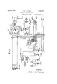
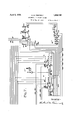
- Fig. 1 shows a calling telephone A leadingin to a line switch B. It also shows a setrelay C for changing the so-termed normal conductors from the-line leading to the line switch B to the corresponding. bank terminals accessible from the finder switch F in Fig. 3.
- the indicatedconnector D normally has access to the line leading to telephone A.
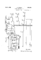
- Fig. 2 shows a first selector E of a group dicates a calling telephone A leading to a line switch L the latter having access to first selector B second selector C third selector J and connector D in Fig. 1,-in sequence, to complete a call from telephone A" in Fig. 2 to the telephone A in Fig. 1. It also shows the arrangement for applying 33-cycle or 50-cycle alternating current over the release trunk to operate set-relay C in Fig. 1. 4 Fig.
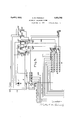
- FIG. 3 shows a line finder switch F involving auxiliary apparatus, the said switch F having access to terminals of a plurality of lines which may be called through connector D in Fig.1, or random connectors in the exchangeofiice containing connector D, wherein contact springs of a set-relay, as C, are interposed.
- Each said line accessible from the switch F has a line relay, as shown on the left aligned with the relays of the said switch.
- the switch F When the switch F operates and seizes a set of its bank terminals corresponding to a line called, its lower group of four wipers are then cooperative with bank terminals which correspond to the impulse sending mechanism which is individual to the said line called, so that while the finder switch F is common to. a plurality of lines, the sending inechanisms are each individual to a said ine.
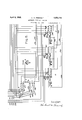
- Fig. 4 shows a first selector G companion to and individual to the switch F in Fig. 3.
- the first selector G has access to other switches in common with first selector E in Fig. 2.
- Fig. 5 shows the impulse sending mechaaccessible from the line switch B. It also in nism for directing the forwarding of calls.
- the said impulse sending mechanism is individual to the line leading to telephone A, and
- Fig. 6 shows switches H, I and J, being the digit setting switches for the first three digits of the number (of five digits) of the line to which calls directed to the line leading to telephone A are to be forwarded to. It also shows a relay Y operated by the clock Z, so that at various hours the normal setting will be different, according to prearrangement.
- Fig. 7 shows switches K and L, being the digit setting switches for the last two digits of the number of the line to which calls directed to the line leading to telephone A are to be forwarded'to.
- switch M which distributes to the switches H to L.
- Fig. 8 is a diagram showing the assembly of the seven sheets of accompanying drawings to disclose the circuits employed to exemplify the present invention.
- the lines extending toward the margins which register are continuations of the same line.
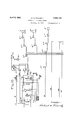
- Fig. 9 shows a modification of Fig. 1,
- Fig. 7 also shows the wherein the harmonic relays a and b are displaced by a single simple relay 0*, to enable the series of eleven impulses used in setting the set-relay G-to be also used thereafter at 'will in unset-ting the set-relay C, in place of sending a series of twelve impulses to unset the set-relay C, as contemplated:in the organization employing Figs. 1 and 2.
- Fig. 10 shows a modification of Fig. 2 and is used in the organization of figures wherein Fig. 9 is employed in place of Fig. 1 and wherein Fig. 10 is employed in place of Fig. 2.
- Fig. 11 is a diagram showing the assembly of sheets wherein Figs. 9 and 10 are employed in place of Figs. shown in Fig. 8.
- the telephone A in Fig. 1 (also shown in Fig. 9) is the Well known common battery series type, but is equipped with an automatic calling device and dial as disclosed in my said pending application Ser. No. 262,626, filed March 19, 1928, and illustrated in Fig. 10 thereof.
- the dial enables aseries of eleven open impulses, or a series of twelve open impulses, to be sent responsive to operating and releasing a specific finger-hold depression p0- sitioned after the 0 digit finger-hold.
- the line switch B in Fig. 1 (also shown in Fig. 9) is of the well known rotary class as described on page 53 of Hersheys Automatic Telephone Practice, third edition.
- Fig. 9 is of the well known type as shown in Fig. 73 of the fourth edition of the said Hershey book.
- the first selector E in Fig. 2 (also shown in F3 g. 10) is of the well known type sometimes called a Powell selector, and described on pages 59 to 61 of the said third edition of Hershe s book. a
- the rst selector G in Fig. 4 is of the well known said Powell type.
- selectors B C E, F and J 2 in Fig. 2 and D in Fig. 4 and the selectors B C E F and J 2 in Fig. 10, are like selector Ci in Fig. 4.
- the line switch L in Fig. 2 (also shown in Fig. 10) is like switch B in Fig. 1.
- the connectors H and G in Fig. 2 are like connector D in Fig. 1 (also shown in Fi 9).
- the line finder switch F in Fig. 3 is of the class shown and described on pages 55 to 57 of the said third edition of Hersheys book, however, modified for the purposes of the present invention.
- the switch elements R and S in Fig. 5, and the switch elements H, I and J in Fig. 6,,and the switch elements K, L and M in Fig. 7, and the switch element 0 in Fig. 3, belong to the class of switch B in Fig. 1, modified in accordance with the present invention.
- the selector E aligns its wipers with the eleventh level of bank terminals, it operates in the well known manner to rotate in and seize by its wipers 205 and 207 the first set of idle bank terminals 208 to 210 of the eleventh level.
- the latter said set will be the ones corresponding to slow-releasing relay 212.
- the latter said relay will actuate responsive to the seizing by selector E when its relay 213 actuates, and ground from winding of transformer TT, applied through spring 214, will be applied through bank terminal 208, wiper 205, spring 215, release trunk conductor 216, bank terminal 13, wiper 17, spring 26, conductor 27.
- relay 24 At the time relay 24 actuates, its armature 33 applies ground to the winding of magnet 34 of the set-relay C.
- the latter said magnet Will cause the springs of relay C to be operated, and the dog latched over the catch 36 to retain the springs of relay C operated after the winding of magnet 34 has been deener zed.
- tonefrom source T is being applied through armature 38, audible to the party at telephone A, indicative to him that the relay C 1s in its latched or set condition, assuming that its circuit energized from the relay 24 is operative.
- the party at telephone A upon hearing the tone from source T will know that his line is in set condition, and will hang up his receiver, leaving his line set, the dog 35 retaining the springs of relay C operated. It will be noted that the relay 24 is maintained actuated as long as selector E has its wiper 205 on bank terminal 208, which condition endures until the party at telephone A hangs up his receiver to cause the relay 212 to deenergize and remove the holding ground from the release trunk 216, which will cause the shaft of the selector E to restore in the obvious manner.
- the party at telephone A will then operate his calling device dial in accordance with the special finger-hold depression to efiect a series of twelve open impulses, which will step the shaft of selector E vertically in accordance with the series and select the relay 217 in the manner as when the party at telephone A directed the setting of his line by the relay 212. That is, ground through the secondary winding of the transformer T will be applied through the spring 218 over conductor 216 to sustain the switch B in seizure, and 50- cycle alternating current will be applied through transformer T over the release trunk 216, operativelyefl'ective to harmonic actuate in a local circuit of relay b.
- tone from the source T will be applied through spring 44, audible to the party at telephone A, indicative that the relay 0 has been unset.
- the party at telephone A upon hearing the tone from source T will know that his line has been unset, and will, therefore, hang ⁇ up. his receiver. The latter will cause the aft Uall to the line leading to telephone A wnder normal condition wherein the relay 0' is not set Assume that the party at telephone A desires to call the telephone A (Fi 1), under normal conditions.
- the dial at te ephone A will be operated in accordance with digits 22211 after initiating the call. This will successively operate the selectors B C and J 2 and connector D, so that wipers 65, 66 and 67 will seize bank terminals-71, 72 and 73, respectively.
- Spring 306 on relay 302 will attract from the resting contact to make contact, while spring 301 remains inert for thetime being.
- This condition causes all the bank terminals accessible from the wiper 311 of the group of wipers 310 to 313 and 337 to 340 to be grounded by the spring 314 of relay 305, excepting the bank terminal 315 corresponding to the relay 302, due to the attracted condition of spring 306.
- Ground is applied from the spring 314, conductor 317, spring 318 to the winding of slow-releasing relay 319, the latter said relay actuating.
- the spring 321 applies ground to the lower terminal of the winding of relay 323, while the ground on the bank terminals successively engaged by wiper 311 is applied through Springs 324 and 325 to the upper terminal of the winding of relay 323.
- the latter said ground is also applied through the interrupter spring of motor magnet 327 to the winding thereof, the said motor magnet operating to successively step advance the wipers 310 to 313 and 337 to 340.
- relay 323 Due to the marginal adjustment of the motor magnet, it will cease operating under the condition, but the relay 323 will operatively energize under the condition.
- relay 323 actuates, ground through spring'321 will be applied through attracted spring 324, wiper 311, bank terminal 315, spring 306, upper winding of relay 302, the latter said relay fully operating. This disconnects the lower winding ofthe latter said relay 302 at spring 301 and connects ground received from the connector D over conductor through spring 301, bank terminal 315, wiper 311 to spring 324 to maintain the relay 323 locked before the spring 321 has had time to retract.
- the relays 303 and 305 will now deactuate if there is no other relay like relay 302 with its lower winding energized, due to a waiting call.
- relays 303 to 305 are actuated after relay 302 fully actuates, the ground applied over conductor 317 will be continued through springs 318 and 330 to the spring corresponding to 318 of the next finder switch (not shown) like F of the group ofwhich switch F is one.
- Ground is applied through spring 348, wiper 338, bank terminal 342, conductor 349 to the winding of relay 505, the latter said relay actuating.
- Ground will now be applied from spring 506, wiper 509 of set 507 to 509, bank terminal 510, bank terminal 511, wiper 513 of set 512 to 515, bank terminal 516, spring 517 to the winding of relay 518 the latter said relay actuating and locking through springs 519 to 520 to ground.
- the interrupter I revolves at the rate of approxi mately twelve times per second, so that the next ground impulse applied thereby will be applied through spring 521, spring 522 to the winding of relay 523, and through spring 524 to the winding of motor magnet 525 of switch R, the said relay 523 and magnet 525 coincidently operating.
- the wiper 512 to 515 will thus be step advanced responsive to the groundings of the interrupter I.
- bank terminal 510 of switch S is connected over conductor 527 to wiper 608 of set 608 to 610 of switch H, bank terminal 612 of set 612 to 614, spring on relay Y, jumper 601, conductor 615 to bank terminal 528 of switch R, the latter said terminal corresponding to a single open impulse for the digit 1.
- bank terminal 529 of switch S is connected over conductor 530, wiper 617 of set 617 to 619 of switch I, bank terminal 620 of set 620 to 622, spring on relay Y, jum er 602, conductor 623 to bank terminal 531 0 switch R.
- Bank terminal 532 of switch S is connected over conductor 533, wiper 624 of set 624 to 626 of switch J, bank terminal 627 of set 627 to 629, spring on relay Y, jumper 603, conductor 630 to bank terminal 534 of switch R.
- Bank terminal. 535 of switch S is connected over conductor 536, wiper 701 of set 701 to 703 of switch K, bank terminal 704 of set 704 to 706, conductor 707, spr-in on relay Y, jumper 604, conductor 623 to bank terminal 531 of switch R.
- Bank terminal 537 of switch S is connected over conductor 538, wiper 708 of set 708 to 710 of switch L, bank terminal 711 of set 711 to 713, conductor 14, spring on relay Y, jumper 605, conductor 615 to bank terminal 528 of switch R.
- the first impulse (series) sent from the spring 501 causes the selector G to, operate its wipers into alignment with the first level of bank terminals, and in the well known manner, select the first idle trunk therein leading to second selector D.
- the second series of three impulses sent by the sprin 501 will be effective to operate the secon selector D in the well known manner to select third selector F
- relay 541 deactuates, follow ing thelast (fifth) digit series sen't while wiper 507 still rests on bank terminal 553, and the said wiper 507 then moves to bank terminal 554, ground received from spring 520 will be applied through bank terminal 554, wiper 507, conductor 556, bank terminal 341, wiper 337, spring 350, make-before-break spring 351 to the winding of relay 352, the latter said relay actuating, followed by the deactuation of relay 335.
- the windings of the line relay in the connector H will be energized over a series path including the conductors 403- 347 springs 357358 and winding of the polarized relay 360.
- the current derived from the line relay in the connector H - will energize relay 360 so that its armature will tilt clockwise into the indicated Ring. pos., the connector H now applying signahng current to the called line leading to telephone A.
- trunk leading-in to selector D from the banks of selector G. This will also apply to the trunk leading-in to selector D from the banks of selector E.
- the eflfective operation will be the same as if the said repeaters were not employed, being used for translating from three wires to two wires for the inter-oflice trunk.
- relay 518 will unlock.
- the sprin 560 of relay 518 will now apply ground through wiper 508 to cause motor magnet 550 to restore wipers 507 to 509 to normal position as drawn.
- the spring 561 of relay 518 will now apply ground through wiper 515 to cause motor magnet 525 to restore the wipers 512 to 515 to normal position as drawn.
- connection-finding party hangs If it is assumed that the calling party at telephone A hangs up first upon the termination of the conversation, this will cause the line relay of connector D to deactuate, followed by the release of the antecedent switches D C, B and L connector D remaining in seizure.
- the current traversing the winding of relay 360 will be reversed, causing relay 363 to deactuate to open the path including retardation coil 380, so that the back-bridge relay in connector D will deactuate to release the wipers of the latter said connector.
- ground is removed from the conductor 75
- relays 323 and 352 will deactuate to open the circuit path including the winding of relay 360 and cause the line relay of connector H to deactuate. Since the back-bridge relay ofthis connector H deactuated responsive to the party at telephone A hanging up, the wipers of connector H will release, the circuits used in the call being now normal.
- Party at telephone A may change the normal prearranged setting for forwarding call to telephone A'- to a random desired line bank terminals 529, 532, 535 and 537"followin bank terminal 510 are connected to wipers 617, 624, 701 and 708 of switches I, J, -K and L, respectively.
- relay 24 will be in its actuated condition while the party at telephone A maintains his receiver oif the switch-hook, so that a circuit can be traced from line terminal 81, conductor 82, attracted spring 83, conductor 84, upper winding of relay 715 to grounded battery. Also, a circuit can be traced from terminal 85, conductor 86, attracted spring 87, conductor 88, lower winding of relay 715 to ground, the latter said relay actuating.
- the slow-releasing relay 716 actuates, energized in a local circuit of relay 715.
- Belay 717 then actuates, energized in a local circuit of relay
- the relay 715 When the party at telephone A hangs up his receiver after setting set-relay C, forthwith, without annexing any di its, the relay 715 will deactuate, its spring 718 applying ground through springs 719, winding of slow-releasing relay-7 20, wiper 7 22 of set72-1 and 7 22, bank terminal 723, conductor 724 to the winding of motor magnet 632, the latter said magnet stepping the wipers of switch H one step from the drawn position.
- Relays 716 and 717 will deactuate consistent with the slow-releasing characteristic of relay 716.
- wiper 709 normally grounds conductor 726, and, therefore, similarly normally grounds wipers 609, 618, 625 and 702. So when the wiper 609 moved to bank terminal 633 this ground is continued over conductor 634, spring 728, conductor 729 to all the bank terminals engageable by wiper 610 at ofi-normal positions.
- the motor magnet 632 will operate by interrupter action to restore the wipers of the switch H to the drawn position, so that It will also be noted that when relay 720 ac tuates, its spring 7 30 applies ground to the winding of the motor magnet 7 32 of switch M, so that when relay 720 deactuates following the impulse sent to the motor magnet 625, the spring of the motor magnet 7 32 will advance the wipers 721 and7 22 one step. When the relay 717 deactuates, round will be applied through spring 735, ank terminals cooperative with wiper 721, interrupter springon the motor magnet 732 to the winding of the latter said motor magnet, causing it to operate and step the wipers 7 21 and 722 to switch M around to the drawn position.
- first digit 1 constituted of one open impulse
- relay 715 will cause relay 715 to momentarily retract spring 718, so that a ground impulse will be sent from said spring 718, spring 719, winding of relay 720, wiper 7 22, bank terminal 723, conductor 724 to the winding of motor magnet 632, the wipers of switch H being thereby stepped one step so wiper 608 will now rest on bank terminal 635 when the armature of said motor magnet 632 retracts.
- the spring 7 30, when retracting will cause the operation of motor magnet 7 32 to advance the wipers of switch M one step, so that wiper 721 will now rest on bank terminal 737.
- second digit 4 constituted of four open impulses
- relay 715 will cause relay 715 to momentarily retract its spring 718 four times, so that four ground impulses will be sent from the spring 718, spring 719, winding of relay 720, wiper 7 22, bank terminal 738, conductor 739 to the winding of motor magnet 642, the wipers of switch I being thereby stepped four steps so that wiper 617 will'now rest on bank terminal 643.
- the retraction of spring 730 will cause the operation of motor magnet 732 to advance the wipers of switch M one step, so wiper-722 will now rest on bank terminal 740.
- third digit 3 constituted of three open impulses
- relay 715 will cause relay 715 to momentarily retract its spring 718 three times, so that three ground impulses will be sent from spring 718, spring 719, winding of relay 720, wiper 722, bank terminal 740, conductor 741 to the-winding of motor magnet 652, the wipers of switch J being thereby stepped three steps, so that wiper 624 will now rest on bank terminal 653.
- the retraction of spring 730 will cause the operation of motor magnet 732 to advance the wipers of switch M one step, so wiper 722 will now rest on bank terminal 742.
- fourth digit 2 constituted of two open impulses
- relay 715 will momentarily retract its spring 718 two times, so that two ground impulses will be sent from spring 718, spring 719, winding of relay 720 wiper 722, bank terminal 742, conductor 743 terminal 746.
- the retraction of spring 730 will cause the operationof motor magnet 732 to advance the wipers of switch M one step, so wiper 722 will now rest on bankterminal 748.
- jumpers 601 to 605 set the sending mechanism to send the digits 1343-l corresponding to the telephone number of telephone A, when the wipers 608, 617, 624, 7 O1 and 708 are in their normal positions as drawn, this same set-up may be attained by directively setting the latter said wipers on the bank positions corresponding to digits 1-34-31, respectively. That is to say, it is not necessary to have the jumpers 601 to 605, but to do away with them will make it necessary to always directively set, not only set-relay C, but also the switches H to L in accordance with a telephone number.
- Tone indicates when switch L is set When the party at telephone A has set the switch L responsive to the last digit of the desired number 14321, for example, tone from source T will be applied through a portion of the winding of the motor magnet 750, wiper 710, a cooperating bank terminal, condenser 755, conductor 88, audible to the party at telephone A. This will indicate that the last switch L operated.
- relays .24, 715, 716 and 717 Upon the party at telephone A hanging up his receiver, relays .24, 715, 716 and 717 will deactuate; also, the relay 212, the windings of which have been in multiple with the windings of relay 715.
- the wiper 709 being off the bank terminal it is drawn resting upon, and is resting upon bank terminal 756, when relay 717 deactuates there will be no ground applied through the springs of this relay from wiper 709, so the wipers of the switches H to L will not be restored at this time.
- retracted spring 735 causes the wipers of switch M to restore, to the drawn position by interrupter action of its motor magnet 732.
- Unsettz'ng the relay 0 and switches H to L When the party at telephone A desires to unset his line for forwarding calls directed thereto, he will remove his receiver as if to initiate a call, and thereupon operate his calling device dial in accordance with the finger-hold used in sending a series of twelve open impulses, as has been set forth. This will cause the relays b and 31 to operate in the manner before described to unlatch the catch 36 to release the springs of the relay C. Ground will now be applied through spring 90 conductor 91, multipled springs on relay 717, bank terminals cooperative withwipers 610, 619, 626, 703 and 710, through the interrupter contacts of the motor magnets of switches H to L, respectively, to restore the said switches to the drawn positions.
- the switches H to L are drawn with five sets of bank terminals. In a commercial embodiment there would be eleven such sets' a normal position set, and a position set or each digit from 1 to 0, so that numbers having digits of random value may be set by the switches H to L, and not limited to the digit 4 in each case,- as in the exemplary embodiment in the accompanying drawings.
- the attraction of spring 92 deenergizes the relay 93, and the latter said relay will then deactuate consistent with its slow-releasing characteristic.
- the ringing generator G is applied through spring 95, spring 79, bell of telephone A and back through the winding of relay 7 8 to grounded battery. The bell at telephone A will thus ring during the time the relay 93 is actuated.
- the relay 7 8 may have a metal tube over its electromagnetic core to make it less sensitive to the alternating current from the source G.
- relay 78 winding of relay 78, as if the connector D had seized the line leading to telephone A under the condition that relay C is unlocked.
- the ring-cut-ofl' relay in the connector D will be operated through the receiver at telephone A and the extension towards the finder switch F terminals will be cut ofi.
- the party at telephone 'A will nowbe in communication with the calling party.
- the party at telephone A can at any time intercept a conversation which has been forwarded from his line, but to do this he must first send the proper series of impulses to unlock the set relay C.
- the relay Y is provided to change from the set of jumpers 601 to 605, corresponding to telephone number 13431, which is the number of telephone A, to a set of jumpers 671 to 675, corresponding to telephone number
Landscapes
- Engineering & Computer Science (AREA)
- Computer Networks & Wireless Communication (AREA)
- Structure Of Telephone Exchanges (AREA)
Description
April 5, 1932. H. M. FRIENDLY AUTOMATIC TELEPHONE SYSTEM Filed May 19, 1950 9 Sheets-Sheet l IHVE'HiDl" 7/7, W
April 1932- H. M. FRIENDLY 4 1,852,745
AUTOMATIC TELEPHONE SYSTEM Filed May 19, 1950 9 Sheets-Sheet 2 m I: i; 3% g 2 m ml LII I April 1932- H. M. FRlE NDLY 1,852,745
AUTOMAT IC TELEPHONE SYSTEM Filed May 19, 1950 9 sheets sheet 5 April 1932- H. M. FRIENDLY 1,852,745
AUTOMATI C TELEPHONE SYSTEM Fi y 1 950 9 Sheets-Sheet 4 [u w l :5 5' q [1* 2'" [E H [*1 m [D [u m m m u:
*tl h Invenmr- April 5, 1932. H. M. FRIENDLY AUTOMATIC TELEPHONE SYSTEM Filed May 19, 1930 v 9 Sheets-Sheet 5 9 Sheets-Sheet 6 Invenmr 7% 2 M H. M. FRIENDLY AUTOMATIC TELEPHONE SYSTEM Filed May 19, 1950 April 5, 1932.
H. M. FRIENDLY 1,852,745
AUTOMATIQ TELEPHONE SYSTEM Filed May 19. 1930 9 sheets sheet 7 April 5, 1932.
April 1932- H, M. FRIENDLY 1,852,745
AUTOMATIC TELEPHONE SYSTEM Filed May 19, 1930 9 Sheets-Sheet 8 Invarfiur- April 1932- HUM. FRIENDLY 1,852,745
I AUTOMATIC T ELEPHONE SYSTEM Filed May 1 9, 1930 Q SheetS Sheet 9 m q: x h n] Q g Q N 11 u N II 1 L1 m J m II N Inventnr- Y Patented Apr. 5, 1932 UNITED STATES PATENT OFFIC HERBERT M. FRIENDLY, OF CHICAGO, ILLINOIS; MILTON S. FRIENDLY AND CENTRAL TRUST COMPANY OF ILLINOIS EXECUTORS DECEASED OF S AID HERBERT M. FRIENDLY,
Application filed May 19, 19:30. Serial No. 453,798. I
The present invention relates to telephone systems; more particularly, so-called automatic or machine switching. telephone systems.
General objects The general objects of the present invention are to enable a subscriber of the automatic telephone system, who contemplates temporarily leaving the location of his telephone, to direetively set central ofiice apparatus or call-forwarding equipment associated with his line, through the agency of his automatic calling device dial .on his tele phone, so that in case any calls are thereafter directed to his line, the latter said calls will be further extended or forwarded to a predetermined random subscribers line or other line of the system. That is, for example, a
subscriber before leaving the premises may remove the receiver of his telephone as if to initiate a call, and then operate his calling device dial by placing his forefinger in a specific depression finger-hold of the dial and then draw the dial until his finger encounters the finger-stop, so that, when the dial is released, it will send a series of eleven open impulses. After the dial has restored, he will restore the receiver, leaving the central office call-forwarding equipment in the set condition.
However, in accordance with the present invention, in the event that the before-mentioned (normally) predetermined line is not the line to which it is, in the particular instance, desired to have the calls forwarded, the said predetermined line may be directively changed. The latter is accomplished by annexing the telephone number of the line to which it is desired to have calls forwarded in the particular instance, forthwith after operating the dial to efiect the series of eleven open impulses mentioned. The receiver will then be restored to the switch-hook, leaving the set line in condition for forwarding calls directed to it to the specific line indexed by the number annexed after primarily setting the line by the series of eleven open impulses. That is to say, not only is there a normally predetermined line to which calls may be forwarded when a set condition exists on a line called, but this normally predetermined line may be temporarily changed to a random' desired line of the exchange. 5
In connection with the last foregoing, relating to changing from the normally predetermined line to a random desired-line to which calls will be forwarded under the set condition, when the subscribers line is to be .be set by sending a series of eleven open impulses, and without annexing any digits.
It will thus be perceived that the present invention is adapted for use in connection with a subscribers telephone line wherein it may be desired to have calls which may be made thereto, in the absence of the subscriber, forwarded to a desired random line of the exchange as may be predetermined by the subscriber whenhe sets his line for forwarding calls made thereto. That is, a residence subscriber may leave his residence and go to the residence of some other random subscriber, and desires that all calls made to his telephone be forwarded to the telephone of the subscriber where he will be found. Moreover, a business establishment may wish to have some employee respond to after business hours calls. The line will, therefore, be set to forward calls made to it to any desired telephone of an employee, perhaps a different employee being selected for successive days.
That is, there may be a predetermined em- General operation Reference is made to my Patents No. 1,772,713, Aug. 12,1930; No. 1,800,788, April 14, 1931; No. 1,806,288, May 19, 1931; No. 1,759,190, May 20, 1930; and No. 1,760,823, May 27, 1930. These patents are directed to a telephone system and apparatus having objects'broadl as set forth in the foregoing statements. he resent invention has features believed to e novel, not disclosed in the said cited patents. Some of these latter said novel features will be specifically described and pointed out in the present specifications, while other novel features will be apparent in view of the disclosures specifically set forth in the specifications and draw ings. Certain of the subjoined claims may be read on the structure of the present disclosure 0 and said patents, but they differ as to scope from claims asserted in the patents referred to filed prior to the present application.
Among the features of the present application believed to be novel over the disclosures in the said prior patents and other prior art are I a. Means for momentarily applying signaling current to the line primarily called, under the condition that the said line is set to cause calls thereto to be forwarded. That is, so that in the event that the party at telephone A on the exampled line should forget to unset the line, he will be prompted, by his bell momentarily ringing, that a call has been made to his line and that it is being forwarded. In case the party at telephone A wishes to intercept the call, he will remove his receiver and unset the set-relay C by operating his dial for sending a series of twelve impulses, which will cause the relay 6 to actuate, and in turn cause the latch 36 to be released to unset the line leading to telephone A.
6. Means for automatically changing the 5 normal settting, involving the switches H to L, by a clock in accordance with the time of day, so that simply setting the set-relay U will not only pre-s'et the corresponding line so that calls made thereto will be forwarded o to a predetermined line of the system, but
that this predetermined line will be changed in accordance with the progress of the time of day. That is, during predetermined hours of the day calls will be forwarded to some certain line, and during other predetermined hours it will be forwarded to some other predetermined line. This is accomplished through the agency of relay Y being operatively energized by the operation of the clock mechanism Z. The clock mechanism will, as
current back over an extended connection from the line (leading from tele hone A) from which calls are to be forwar ed. This involves a source of 33-cycle alternating current and a source of 50-cycle alternatin current, a desired one of which may be se acted in accordance with the operation of the dial of the telephone of the line concerned. There are provided a pair of harmonic relays a and b, which are selectively responsive to the said sources of alternating current. Thus, when the party at telephone A Wishes to set the set-relay 0 he will initiate a call and operate the selector E in accordance with a series of eleven open impulses sent from his dial. This will cause the selector E to select the indicated 33-cycle source of alternating current, and cause it to be applied over the release trunk, operatively effective to relay a, which, in turn, causes the set-relay Gto become actuated and locked. In the same manner, a series of twelve impulses sent from the dial will cause the selector E to select the indicated 50-cycle source of alternating current, and cause it to be a plied over the release trunk, operatively e ective to the relay 6, which, in turn, causes the set-relay C to become unlocked.
A modification of the last foregoing outlined arrangement for setting and un-setting the set-relay G is shown in modification Fig. 9, used in place of Fig. 1, and wherein the cooperating modification Fig. 10 is employed in place of Fig. 2. That is to say, the Figs. 1 and 2 are displaced by Figs. 9 and 10 in the organization of figures indicated in Fig. 11 to illustrate the changed system from that indicated by Fig. 8. In the arrangement exemplified by the Figs. 9 and 10 when substituted for Figs. 1 and 2, sending a series of eleven impulses from the calling dial to telephone A (in Fig. 9), will cause the relay 0 to actuate from 33-cycle alternating current. This operation will cause the set-relay C to operate if it is not locked, and cause the said set-relay C to unlock if it is locked.
d. A meter M is provided for the line to record the number of times the set-relay C has been set for forwarding calls.
0. A meter M is provided for the line to record the number of times a finder switch,
as F, finds a line that has been called, and wlliich latter said line is set for forwarding ca ls.
f. A meter M is provided for the line to record when a call has been forwarded to a line and a response made on the latter said line. Moreover, two ground-path interrupters P and Q, are provided, adapted to each have a specific rate of interruption of the ground path. A relay (Z is provided for I changing from one of said interrupters to the other in accordance with the time of day, under control of-the clock C The interrupter, P or Q, which ever is operative, will drive the wipers of the timing switch 0 to cause the meter M to be successively, operated at re-occurring periods, so that the elapsed time of holding a forwarded call after a response is obtained, will be recorded 5 by the meter M having in mind that the time of day the call durates through will be a Drawings With reference to the accompanying drawings:
Fig. 1 shows a calling telephone A leadingin to a line switch B. It also shows a setrelay C for changing the so-termed normal conductors from the-line leading to the line switch B to the corresponding. bank terminals accessible from the finder switch F in Fig. 3. The indicatedconnector D normally has access to the line leading to telephone A.
Fig. 2 shows a first selector E of a group dicates a calling telephone A leading to a line switch L the latter having access to first selector B second selector C third selector J and connector D in Fig. 1,-in sequence, to complete a call from telephone A" in Fig. 2 to the telephone A in Fig. 1. It also shows the arrangement for applying 33-cycle or 50-cycle alternating current over the release trunk to operate set-relay C in Fig. 1. 4 Fig. 3 shows a line finder switch F involving auxiliary apparatus, the said switch F having access to terminals of a plurality of lines which may be called through connector D in Fig.1, or random connectors in the exchangeofiice containing connector D, wherein contact springs of a set-relay, as C, are interposed. Each said line accessible from the switch F has a line relay, as shown on the left aligned with the relays of the said switch.-
When the switch F operates and seizes a set of its bank terminals corresponding to a line called, its lower group of four wipers are then cooperative with bank terminals which correspond to the impulse sending mechanism which is individual to the said line called, so that while the finder switch F is common to. a plurality of lines, the sending inechanisms are each individual to a said ine.
Fig. 4 shows a first selector G companion to and individual to the switch F in Fig. 3. The first selector G has access to other switches in common with first selector E in Fig. 2.
Fig. 5 shows the impulse sending mechaaccessible from the line switch B. It also in nism for directing the forwarding of calls. The said impulse sending mechanism is individual to the line leading to telephone A, and
it is seized by the switch F when the latter said switch seizes the bank terminals which are companion to the connector bank terminals of the line leading to telephone A.
Fig. 6 shows switches H, I and J, being the digit setting switches for the first three digits of the number (of five digits) of the line to which calls directed to the line leading to telephone A are to be forwarded to. It also shows a relay Y operated by the clock Z, so that at various hours the normal setting will be different, according to prearrangement.
Fig. 7 shows switches K and L, being the digit setting switches for the last two digits of the number of the line to which calls directed to the line leading to telephone A are to be forwarded'to. switch M, which distributes to the switches H to L. I
Fig. 8 is a diagram showing the assembly of the seven sheets of accompanying drawings to disclose the circuits employed to exemplify the present invention. The lines extending toward the margins which register are continuations of the same line.
Fig. 9 shows a modification of Fig. 1,
Fig. 7 also shows the wherein the harmonic relays a and b are displaced by a single simple relay 0*, to enable the series of eleven impulses used in setting the set-relay G-to be also used thereafter at 'will in unset-ting the set-relay C, in place of sending a series of twelve impulses to unset the set-relay C, as contemplated:in the organization employing Figs. 1 and 2.
Fig. 10 shows a modification of Fig. 2 and is used in the organization of figures wherein Fig. 9 is employed in place of Fig. 1 and wherein Fig. 10 is employed in place of Fig. 2.
Fig. 11 is a diagram showing the assembly of sheets wherein Figs. 9 and 10 are employed in place of Figs. shown in Fig. 8.
Equipment I The telephone A in Fig. 1 (also shown in Fig. 9) is the Well known common battery series type, but is equipped with an automatic calling device and dial as disclosed in my said pending application Ser. No. 262,626, filed March 19, 1928, and illustrated in Fig. 10 thereof. The dial enables aseries of eleven open impulses, or a series of twelve open impulses, to be sent responsive to operating and releasing a specific finger-hold depression p0- sitioned after the 0 digit finger-hold.
The line switch B in Fig. 1 (also shown in Fig. 9) is of the well known rotary class as described on page 53 of Hersheys Automatic Telephone Practice, third edition.
The connector D in Fig. 1 (also shown in 1 and 2, respectively, as
Fig. 9) is of the well known type as shown in Fig. 73 of the fourth edition of the said Hershey book.
The first selector E in Fig. 2 (also shown in F3 g. 10) is of the well known type sometimes called a Powell selector, and described on pages 59 to 61 of the said third edition of Hershe s book. a
The rst selector G in Fig. 4 is of the well known said Powell type.
The selectors B C E, F and J 2 in Fig. 2 and D in Fig. 4, and the selectors B C E F and J 2 in Fig. 10, are like selector Ci in Fig. 4. I
The line switch L in Fig. 2 (also shown in Fig. 10) is like switch B in Fig. 1.
The connectors H and G in Fig. 2 (also shown in Fig. 10) are like connector D in Fig. 1 (also shown in Fi 9).
The line finder switch F in Fig. 3 is of the class shown and described on pages 55 to 57 of the said third edition of Hersheys book, however, modified for the purposes of the present invention.
The switch elements R and S in Fig. 5, and the switch elements H, I and J in Fig. 6,,and the switch elements K, L and M in Fig. 7, and the switch element 0 in Fig. 3, belong to the class of switch B in Fig. 1, modified in accordance with the present invention.
It will be understood that any other suitable switches may be substituted for the said well known switches mentioned, without departing from the spirit of the present invention. Also, that the switches specific to the present invention may be modified by those skilled in the art without departing from the spirit of the'present invention, as defined by the subjoined claims.
It will, of course, be understood that in a commercial embodiment of the present invention, a plurality of switches in a group will be employed in place of the exemplary single switches used in disclosing the present invention, so that a plurality of calls may be co-existent, the switches in the groups having predetermined order of use with respect to antecedent co-operatlve swltches.
Detailed operationlnitz'atz'ng a call from telephone A to telephone A ing to telephone A, and thus correspondingly set the selectors E, D and F and connector H The connection may then be released in the well known manner, responsive to thecalling party replacing his receiver on the switch-hook. A call to telephone A the telephone number of which is 14321, will be ef- Setting the line leading to telephone A 80 that calls directed to saidline will be forworded to telephone A Let it be assumed that the party at telephone A (in Fig. 1) desires to set his line so that calls directed thereto will be forwarded to telephone A. The party at telephone A will remove his receiver, as if to initiate an ordinary call. This will cause the line switch 13 (in Fig. 1) to operate and select a first selector E. The party at telephone A will then operate his calling device dial in accordance with the special finger-hold depression to efiect a series of eleven open impulses, which will step the shaft of selector E (in Fig. 2) vertically in accordance with the series.
At the time the selector E aligns its wipers with the eleventh level of bank terminals, it operates in the well known manner to rotate in and seize by its wipers 205 and 207 the first set of idle bank terminals 208 to 210 of the eleventh level. The latter said set will be the ones corresponding to slow-releasing relay 212. The latter said relay will actuate responsive to the seizing by selector E when its relay 213 actuates, and ground from winding of transformer TT, applied through spring 214, will be applied through bank terminal 208, wiper 205, spring 215, release trunk conductor 216, bank terminal 13, wiper 17, spring 26, conductor 27. This ground to .the release trunk will, therefore, maintain the relays 213 and 28 actuated as long as the windings of relay 212 are maintained energized through the telephone A by the party thereat maintaining his receiver off the switchhook. It is noted that this latter said ground is in lieu of the ground applied by the spring of release relay of selector E, which ground was applied back over the release trunk responsive to initiating the call.
At the time ground is applied from the winding of the transformer TT over conductor 27, responsive to relay 213 actuating, alternating current of 33 cycles from transformer TT will operate-the harmonic relay (1 in Fig. 1. This will, in turn, cause relay 24 to actuate in a local circuit of relay (1.
At the time relay 24 actuates, its armature 33 applies ground to the winding of magnet 34 of the set-relay C. The latter said magnet Will cause the springs of relay C to be operated, and the dog latched over the catch 36 to retain the springs of relay C operated after the winding of magnet 34 has been deener zed.
en the springs of relay 0 become operated, in a local circuit of relay 24, tonefrom source T is being applied through armature 38, audible to the party at telephone A, indicative to him that the relay C 1s in its latched or set condition, assuming that its circuit energized from the relay 24 is operative.
The party at telephone A, upon hearing the tone from source T will know that his line is in set condition, and will hang up his receiver, leaving his line set, the dog 35 retaining the springs of relay C operated. It will be noted that the relay 24 is maintained actuated as long as selector E has its wiper 205 on bank terminal 208, which condition endures until the party at telephone A hangs up his receiver to cause the relay 212 to deenergize and remove the holding ground from the release trunk 216, which will cause the shaft of the selector E to restore in the obvious manner.
Unsetting the line leading to telephone A so that calls directed to said line will not be forwarded therefrom, the said line then being in normal condition Let it be assumed that the part at telephone A (Fig. 1) desires to unset his line, by
unlocking the relay 0, and thus cause the springs thereof torestore to normal condition. The party at'telephone A will remove his receiver as if to initiate an ordinary call, having in mind that even if the springs of relay C are operated and locked by the dog 35, outgoin calls from telephone A throng the line switch B will be effected normally as if the springs of relay C were not in' their operated condition. I
The party at telephone A will then operate his calling device dial in accordance with the special finger-hold depression to efiect a series of twelve open impulses, which will step the shaft of selector E vertically in accordance with the series and select the relay 217 in the manner as when the party at telephone A directed the setting of his line by the relay 212. That is, ground through the secondary winding of the transformer T will be applied through the spring 218 over conductor 216 to sustain the switch B in seizure, and 50- cycle alternating current will be applied through transformer T over the release trunk 216, operativelyefl'ective to harmonic actuate in a local circuit of relay b.
At' the time relay 31 actuates, and looks through spring 40, spring 41 will apply ground to energize the winding of unlatching magnet 43 of the relay C. This will operate the latter said magnet to unlatch the dog 35 from the catch 36 and cause the springs of relay O to restore to normal condition.
Having in mind that the relay 31 is actuated and held so until the wiper 205' of selector E is restored from bank terminal 221, it
will be obvious that tone from the source T will be applied through spring 44, audible to the party at telephone A, indicative that the relay 0 has been unset.
The party at telephone A, upon hearing the tone from source T will know that his line has been unset, and will, therefore, hang\ up. his receiver. The latter will cause the aft Uall to the line leading to telephone A wnder normal condition wherein the relay 0' is not set Assume that the party at telephone A desires to call the telephone A (Fi 1), under normal conditions. The dial at te ephone A will be operated in accordance with digits 22211 after initiating the call. This will successively operate the selectors B C and J 2 and connector D, so that wipers 65, 66 and 67 will seize bank terminals-71, 72 and 73, respectively. Ground from the conmotor will be a plied over private wiper 65, bank terminal F1, spring 74 to the winding of relay'28, the latter said relay operatin to disconnect the line relay 78 and the ground on the resting contact of spring 79, in the well known manner. The connector D will now apply signaling current efiective to the bell at telephone A, in the well known manner the efiective-circuits being those well known om Hersheys book cite Gall on the line leadinieto telephone A under the conditionthat t set relay 6' is in operated condition.
Now to 67 are set upon the blank terminals 71 to 73, respectively, the set-relay C is in its operated and latched condition. Under the latter said condition the relay 28 will not be energized, since the normal conductors are disconnected from the line leadin to telephone A. However, the latter sald condition does not prevent the party at telephone A normally extending calls from said telephone.
It will be noted ing from bank terminals 71 to 73, disconnected from the line leading to telephone A,
assume that at the time the wipers that the conductors leadare now connected to conductors 75 to 77, respectively. Thus, when the connector D seizes the line terminals 71 to 73, ground dependent common relay 305 to actuate.
' The spring 321 applies ground to the lower terminal of the winding of relay 323, while the ground on the bank terminals successively engaged by wiper 311 is applied through Springs 324 and 325 to the upper terminal of the winding of relay 323. The latter said ground is also applied through the interrupter spring of motor magnet 327 to the winding thereof, the said motor magnet operating to successively step advance the wipers 310 to 313 and 337 to 340. When wiper 311 encounters bank terminal 315 it will not receive ground because of the attracted condition of spring 306, so that the short-circuit is removed from the winding of relay 323 and the direct ground is removed from the winding of the motor magnet 327. Due to the marginal adjustment of the motor magnet, it will cease operating under the condition, but the relay 323 will operatively energize under the condition. When relay 323 actuates, ground through spring'321 will be applied through attracted spring 324, wiper 311, bank terminal 315, spring 306, upper winding of relay 302, the latter said relay fully operating. This disconnects the lower winding ofthe latter said relay 302 at spring 301 and connects ground received from the connector D over conductor through spring 301, bank terminal 315, wiper 311 to spring 324 to maintain the relay 323 locked before the spring 321 has had time to retract. The relays 303 and 305 will now deactuate if there is no other relay like relay 302 with its lower winding energized, due to a waiting call. If the relays 303 to 305 are actuated after relay 302 fully actuates, the ground applied over conductor 317 will be continued through springs 318 and 330 to the spring corresponding to 318 of the next finder switch (not shown) like F of the group ofwhich switch F is one.
The ground received over conductor 75 is applied through springs 331 and 334 to the Winding of relay 335, the latter said relay actuating. Resultant to the actuation of the relay 335 a circuit path can be traced from grounded battery, upper winding of relay 401 to ground, the latter said relay actuating,
followed by slow-r'eleasin release relay 407. Ground will now be applied through spring 408 to release trunk conductor 409.
Ground is applied through spring 348, wiper 338, bank terminal 342, conductor 349 to the winding of relay 505, the latter said relay actuating. Ground will now be applied from spring 506, wiper 509 of set 507 to 509, bank terminal 510, bank terminal 511, wiper 513 of set 512 to 515, bank terminal 516, spring 517 to the winding of relay 518 the latter said relay actuating and locking through springs 519 to 520 to ground.
In this connection, it willbe noted that the interrupter I revolves at the rate of approxi mately twelve times per second, so that the next ground impulse applied thereby will be applied through spring 521, spring 522 to the winding of relay 523, and through spring 524 to the winding of motor magnet 525 of switch R, the said relay 523 and magnet 525 coincidently operating. The wiper 512 to 515 will thus be step advanced responsive to the groundings of the interrupter I. It will be noted that while the spring 501 will attract coincident with the first energization of the motor magnet 525, the spring 502 on relay 526 will maintain the relay 401 in selector G energized until the wiper 514 encounters ground on the first off-normal bank terminal cooperative therewith and thereby energizes relay 526 over an obvious path, after which time the relay 401 in selector G will be. under the sole control of spring 501 on relay 523.
It will appear presently that the call in the present instance is to be forwarded to telephone A, the number of which is 13431, and accordingly, jumpers 601 to 605 in Fig. 6 are run between the jumper cross-connecting terminals X and the jumper cross-connecting terminals corresponding to the springs on relay Y, to predetermine that the sending mechanism in Fig. 5 will send a corresponding train of series of directive digit impulses. It will be noted that the bank terminal 510 of switch S is connected over conductor 527 to wiper 608 of set 608 to 610 of switch H, bank terminal 612 of set 612 to 614, spring on relay Y, jumper 601, conductor 615 to bank terminal 528 of switch R, the latter said terminal corresponding to a single open impulse for the digit 1. In the same manner, bank terminal 529 of switch S is connected over conductor 530, wiper 617 of set 617 to 619 of switch I, bank terminal 620 of set 620 to 622, spring on relay Y, jum er 602, conductor 623 to bank terminal 531 0 switch R. Bank terminal 532 of switch S is connected over conductor 533, wiper 624 of set 624 to 626 of switch J, bank terminal 627 of set 627 to 629, spring on relay Y, jumper 603, conductor 630 to bank terminal 534 of switch R. Bank terminal. 535 of switch S is connected over conductor 536, wiper 701 of set 701 to 703 of switch K, bank terminal 704 of set 704 to 706, conductor 707, spr-in on relay Y, jumper 604, conductor 623 to bank terminal 531 of switch R. Bank terminal 537 of switch S is connected over conductor 538, wiper 708 of set 708 to 710 of switch L, bank terminal 711 of set 711 to 713, conductor 14, spring on relay Y, jumper 605, conductor 615 to bank terminal 528 of switch R.
Returning to the operation of the mechanism in Fig. 5, for each step that the wipers of switch R are advanced, the relay 523 will attract its armature 501. However, until the wipers of switch R have been moved one step off-normal, so that wiper 514 rests on bank terminal 539, at which time the relay 526 will become energized and maintained so until the wipers return to normal, the spring 501 is disabled from efi'ecting open impulses. In view of the fact that ground on spring 506 is applied through wiper 509, bank terminal 510,, conductor 527, wiper 608, bank terminal 612, spring in relay Y, jumper 601, conductor 615 to bank terminal 528, when the wiper 512 encounters the latter said terminal, the spring 501 will have sent one open impulse effective to the relay 401 in selector G. At the time wiper 512 receives ground from bank terminal 528, this ground is applied through wiper 513 and the bank terminal it is resting upon, conductor 540 to the winding of slow-releasing relay 541, the latter said relay actuating and locking by its spring 542, wiper 514 and bank terminal it is resting upon to ground. The relay 541 will thus be maintained locked until the wipers of switch R are returned to normal position, the relay 541 then deactuating consistent with its slow-releasing characteristic to cause a delay between the series of the train to allow for truck hunting by the selector last operated.
Coincident with the actuation of the relay 541, the said locking ground received through wiper 514 is also applied through spring 545, interrupter spring, to the winding of motor magnet 525, the latter said magnet operating to restore the wipers 512 to 515 of switch R to the normal position as drawn, whereat wiper 514 does not derive ground. I
At the time relay 541 actuates, ground is applied through spring 547 to the winding of the motor magnet 550 of the switch S. So that when the relay'541 deactuates, the retraction of the s ring of the latter said motor magnet causes t e wi ers of the switch S to advance one step, so t at wiper 509 will then rest on bank terminal 529.
Ground a plied through wiper 509 will now be on ank terminal 531. Therefore, when the wiper 512 encounters the latter said bank terminal in its new step movement, responsive to the deactuation of the relay 541, three open impulses will have been sent from spring 501. V
The first impulse (series) sent from the spring 501 causes the selector G to, operate its wipers into alignment with the first level of bank terminals, and in the well known manner, select the first idle trunk therein leading to second selector D. The second series of three impulses sent by the sprin 501 will be effective to operate the secon selector D in the well known manner to select third selector F It is thought that, in view of th'e'foregoingi -;it will be clear howthe wipers of switch will be restored to normal following the sending of each digit series, and that the wipers of switch S will thereupon advance one step when the relay 541 deactuates to start the next following series. So that in view of the jumpering (jumpers 601 to 605) the connection will be progressed to telephone A, the number of which is 13431, responsive to the relay 335 of switch F actuating. I
At the time relay 541 deactuates, follow ing thelast (fifth) digit series sen't while wiper 507 still rests on bank terminal 553, and the said wiper 507 then moves to bank terminal 554, ground received from spring 520 will be applied through bank terminal 554, wiper 507, conductor 556, bank terminal 341, wiper 337, spring 350, make-before-break spring 351 to the winding of relay 352, the latter said relay actuating, followed by the deactuation of relay 335.
At this time, the windings of the line relay in the connector H will be energized over a series path including the conductors 403- 347 springs 357358 and winding of the polarized relay 360. The current derived from the line relay in the connector H -will energize relay 360 so that its armature will tilt clockwise into the indicated Ring. pos., the connector H now applying signahng current to the called line leading to telephone A.
When the party at telephone A removes his receiver from the switch-hook in responding, the current fed back from the said line relay in connector H will be reversed in direction, so that the armature of relay 360 will tilt counter-clockwise into the indicated Ans. pos.. When the armature of relay 360 tilts clockwise, slow-releasing relay 362 actuates from the ground on the'latter said armature.
Then, when the latter said armature tilts be a time when both relays 362 and 363 are actuated due to the slow-releasing characteristic of relay 362, and during this time a short-circuit through spring 364 andmakebefore-break spring 365 is across the talking path includes conductors 7 67 7 bank termi nals 366367, wipers 312313, springs 368- 369 and spring 370. This will cause the ringcut-ofi relay in connector D to actuate in the 10 well known manner to complete a talking connection over the traced path including condensers 375376 between the calling telephone A" and the finally called telephone A to which the call to the line leading to telephone A was forwarded. When the relay 362 deactuates, the retardation coil 380 becomes in series with the windings of the back-bridge relay in connector D and this holds the latter said relay actuated.
It will be understood that any well known or other suitable so-termed trunk repeater may be introduced into the trunk leading-in to selector D from the banks of selector G. This will also apply to the trunk leading-in to selector D from the banks of selector E.
The eflfective operation will be the same as if the said repeaters were not employed, being used for translating from three wires to two wires for the inter-oflice trunk.
3o Calling party at telephone A abandons call while call is being forwarded If it is assumed that the calling party at telephone A" abandons the call while the call is being forwarded from the called line (leading to telephone in Fig. 1) to telephone A, it will be clear that connector D and antecedent switches will restore to normal position, subject to new use. 40 This will remove the ground from conductor -75, so that relays 323 and 335 of the switch F will deactuate to render said switch F subject to new use. Relay 505 will deenergize responsive to the deactuation of relay 335,
4 so that relay 518 will unlock. The sprin 560 of relay 518 will now apply ground through wiper 508 to cause motor magnet 550 to restore wipers 507 to 509 to normal position as drawn. The spring 561 of relay 518 will now apply ground through wiper 515 to cause motor magnet 525 to restore the wipers 512 to 515 to normal position as drawn.
Releasing eonneotionUalled party hangs up 1 first If it is assumed that the called party at telephone A hangs up first upon the terminaprimaril y the back-bridge relay in connector D, notwithstandin relay 362 actuates and spring 36% is,tl1erei ore, attracted. The connector D will not release its wipers under tho--present condition. Also, connectbr H will not re-, lease its wipers under the present condition because the line relay of the latter said connector is still maintained energized through the windings of relay 360.
lVhen the calling partyat telephone A now hangs up his receiver, and in view of the fact that the back-bridge relay in connector D is deactuated, connector D will release its wipers, and the connection from telephone A up to and including connector D will be released to normal, subject to new use. Ground being thus removed from the conductor 75, relay '352 will deactuate and open the path including the winding of the relay 360, so that the front-bridge relay in connector H will deactuate and cause the latter said connector to release its wipers, and the antecedent selectors F D D and G to release their wipers, the circuits used in the call being now at normal.
Releasing connection-finding party hangs If it is assumed that the calling party at telephone A hangs up first upon the termination of the conversation, this will cause the line relay of connector D to deactuate, followed by the release of the antecedent switches D C, B and L connector D remaining in seizure. When the called party at telephone A hangs up, the current traversing the winding of relay 360 will be reversed, causing relay 363 to deactuate to open the path including retardation coil 380, so that the back-bridge relay in connector D will deactuate to release the wipers of the latter said connector. When connector D releases, ground is removed from the conductor 75,
' so that relays 323 and 352 will deactuate to open the circuit path including the winding of relay 360 and cause the line relay of connector H to deactuate. Since the back-bridge relay ofthis connector H deactuated responsive to the party at telephone A hanging up, the wipers of connector H will release, the circuits used in the call being now normal.
Party at telephone A may change the normal prearranged setting for forwarding call to telephone A'- to a random desired line bank terminals 529, 532, 535 and 537"followin bank terminal 510 are connected to wipers 617, 624, 701 and 708 of switches I, J, -K and L, respectively.
Before the party at telephone A hung up his receiver, after causing set relay C to be actuated and locked, at which time he perceived the tone from source T, the said party could have changedthe setting from that to cause calls to beforwarded to telephone A as has been described.
Let it be assumed that it is his desire to have the calls directed to his line leading to telephone A forwarded to a random desired line leading to telephone A", the telephone number of which is 14321. The party at telephone A will operate his dial to annex the digits 143,-2'1, following the sending of the series of eleven open impulses to set set-relay C.
It will be noted that under the condition of causing relay G to be set as assumed, the relay 24 will be in its actuated condition while the party at telephone A maintains his receiver oif the switch-hook, so that a circuit can be traced from line terminal 81, conductor 82, attracted spring 83, conductor 84, upper winding of relay 715 to grounded battery. Also, a circuit can be traced from terminal 85, conductor 86, attracted spring 87, conductor 88, lower winding of relay 715 to ground, the latter said relay actuating. The slow-releasing relay 716 actuates, energized in a local circuit of relay 715. Belay 717 then actuates, energized in a local circuit of relay When the party at telephone A hangs up his receiver after setting set-relay C, forthwith, without annexing any di its, the relay 715 will deactuate, its spring 718 applying ground through springs 719, winding of slow-releasing relay-7 20, wiper 7 22 of set72-1 and 7 22, bank terminal 723, conductor 724 to the winding of motor magnet 632, the latter said magnet stepping the wipers of switch H one step from the drawn position. Relays 716 and 717 will deactuate consistent with the slow-releasing characteristic of relay 716.
It will be noted that wiper 709 normally grounds conductor 726, and, therefore, similarly normally grounds wipers 609, 618, 625 and 702. So when the wiper 609 moved to bank terminal 633 this ground is continued over conductor 634, spring 728, conductor 729 to all the bank terminals engageable by wiper 610 at ofi-normal positions. Thus, the motor magnet 632 will operate by interrupter action to restore the wipers of the switch H to the drawn position, so that It will also be noted that when relay 720 ac tuates, its spring 7 30 applies ground to the winding of the motor magnet 7 32 of switch M, so that when relay 720 deactuates following the impulse sent to the motor magnet 625, the spring of the motor magnet 7 32 will advance the wipers 721 and7 22 one step. When the relay 717 deactuates, round will be applied through spring 735, ank terminals cooperative with wiper 721, interrupter springon the motor magnet 732 to the winding of the latter said motor magnet, causing it to operate and step the wipers 7 21 and 722 to switch M around to the drawn position.
However, in the present instance, the party at telephone A does not hang up his receiver forthwith after setting relay C, but, on the other hand, annexes the five digits 1-43- 21 designating the random line leading to telephone A ,'for example. The sending of first digit 1, constituted of one open impulse, will cause relay 715 to momentarily retract spring 718, so that a ground impulse will be sent from said spring 718, spring 719, winding of relay 720, wiper 7 22, bank terminal 723, conductor 724 to the winding of motor magnet 632, the wipers of switch H being thereby stepped one step so wiper 608 will now rest on bank terminal 635 when the armature of said motor magnet 632 retracts. The spring 7 30, when retracting, will cause the operation of motor magnet 7 32 to advance the wipers of switch M one step, so that wiper 721 will now rest on bank terminal 737.
The sending of second digit 4, constituted of four open impulses, will cause relay 715 to momentarily retract its spring 718 four times, so that four ground impulses will be sent from the spring 718, spring 719, winding of relay 720, wiper 7 22, bank terminal 738, conductor 739 to the winding of motor magnet 642, the wipers of switch I being thereby stepped four steps so that wiper 617 will'now rest on bank terminal 643. The retraction of spring 730 will cause the operation of motor magnet 732 to advance the wipers of switch M one step, so wiper-722 will now rest on bank terminal 740.
The sending of third digit 3, constituted of three open impulses, will cause relay 715 to momentarily retract its spring 718 three times, so that three ground impulses will be sent from spring 718, spring 719, winding of relay 720, wiper 722, bank terminal 740, conductor 741 to the-winding of motor magnet 652, the wipers of switch J being thereby stepped three steps, so that wiper 624 will now rest on bank terminal 653. The retraction of spring 730 will cause the operation of motor magnet 732 to advance the wipers of switch M one step, so wiper 722 will now rest on bank terminal 742.
The sending of fourth digit 2, constituted of two open impulses, will cause relay 715 to momentarily retract its spring 718 two times, so that two ground impulses will be sent from spring 718, spring 719, winding of relay 720 wiper 722, bank terminal 742, conductor 743 terminal 746. The retraction of spring 730 will cause the operationof motor magnet 732 to advance the wipers of switch M one step, so wiper 722 will now rest on bankterminal 748.
The sending of the fifthdigit 1,-constituted of one open impulse, will cause relay 715 to momentarily retract its spring 718 one time, so that one ground impulse will be sent from spring 718, spring 719, winding of relay 720, wiper 722, bank terminal 748, conductor 749 to the winding of motor magnet 7 50, the wipers of switch L being thereby stepped one step, so wiper 708 will now rest on bank terminal 751. The retraction of spring 730 will cause the operation of motor magnet 732 to advance the wipers of switch M one step, s wiper 722 will now rest on bank terminal It will be noted that under the last foregoing condition, the bank terminals 510, 529, 532, 535 and 537, cooperative with wiper 509, are now connected through wipers 608, 617, 624, 701 and 708 over the obvious circuit paths to terminals 528, 534, 531, 558 and 528, respectively. Under this condition, it will be clear that the sending mechanism will be set to send the train of digits 143-2--1 responsive to the terminals 71 to73 being seized by the wipers of connector D.
In this connection, it will be understood that although the jumpers 601 to 605 set the sending mechanism to send the digits 1343-l corresponding to the telephone number of telephone A, when the wipers 608, 617, 624, 7 O1 and 708 are in their normal positions as drawn, this same set-up may be attained by directively setting the latter said wipers on the bank positions corresponding to digits 1-34-31, respectively. That is to say, it is not necessary to have the jumpers 601 to 605, but to do away with them will make it necessary to always directively set, not only set-relay C, but also the switches H to L in accordance with a telephone number.
Tone indicates when switch L is set When the party at telephone A has set the switch L responsive to the last digit of the desired number 14321, for example, tone from source T will be applied through a portion of the winding of the motor magnet 750, wiper 710, a cooperating bank terminal, condenser 755, conductor 88, audible to the party at telephone A. This will indicate that the last switch L operated.
Upon the party at telephone A hanging up his receiver, relays .24, 715, 716 and 717 will deactuate; also, the relay 212, the windings of which have been in multiple with the windings of relay 715. The wiper 709 being off the bank terminal it is drawn resting upon, and is resting upon bank terminal 756, when relay 717 deactuates there will be no ground applied through the springs of this relay from wiper 709, so the wipers of the switches H to L will not be restored at this time. However, retracted spring 735 causes the wipers of switch M to restore, to the drawn position by interrupter action of its motor magnet 732.
I f only part of switches H to L are set they will restore In this connection it will be noted that if the party at telephone A, when setting the switches H to L, had failed to set all of the latter said switches, by leaving off one or more of the five digits, the wiper 709 would then be in the drawn position, resting on bank terminal 712. So when relay 717 deactuates responsive to the hanging up of the receiver of telephone A, the ground on wiper 709 will be applied through bank terminal 712, conductor 726, and in multiple through those of wipers 609, 618, 625 and 702 as are in off-normal position, respective bank terminals cooperated with the latter said wipers, conductor 634, and through the multipled springs of said relay 717 to the bank contacts cooperated with wipers 610, 619, 626 and 703 to the respective motor magnets of the switches H to K, the wipers of which are oif-normal, to restore the wipers of these switches to the drawn normal positions, the switch M restoring to the drawn normal position responsive to the retraction of armature 735, in the manner before described.
Under the latter said restored condition of the switches H to M any calls directed to the line leading to telephone A will be forwarded to telephone A in accordance with the jumpers 601 to 605 and the settings of the switches when in the drawn positions, since only relay C will now be set.
Unsettz'ng the relay 0 and switches H to L When the party at telephone A desires to unset his line for forwarding calls directed thereto, he will remove his receiver as if to initiate a call, and thereupon operate his calling device dial in accordance with the finger-hold used in sending a series of twelve open impulses, as has been set forth. This will cause the relays b and 31 to operate in the manner before described to unlatch the catch 36 to release the springs of the relay C. Ground will now be applied through spring 90 conductor 91, multipled springs on relay 717, bank terminals cooperative withwipers 610, 619, 626, 703 and 710, through the interrupter contacts of the motor magnets of switches H to L, respectively, to restore the said switches to the drawn positions. The latter said restorations eiface the specifically set up condition efi'ected by the switches H to L. The line leading to telephone A will therefore become in its normal, unused condition when the party at telephone A hangs up his receiver and causes selector E to restore and relay 31 to deactuate.
The switches H to L are drawn with five sets of bank terminals. In a commercial embodiment there would be eleven such sets' a normal position set, and a position set or each digit from 1 to 0, so that numbers having digits of random value may be set by the switches H to L, and not limited to the digit 4 in each case,- as in the exemplary embodiment in the accompanying drawings.
The five switches H to L contem lates a train of five digit series. It will e clear that more switches ma be added to increase this ran e, the switch 1 having corresponding ban positions added.
I Additional features 7 The general operation of the system hav- Signaling current momentarily applied to the primarily eaZZed line when it is seized by a connector under the condition of said line being set for forwarding calls made to it With reference to the paragraph a at the outset, it will be noted that when a connector as D seizes the line leading to telephone A (Fig. 1), under the condition that the relay C is locked, ground applied from the connector through the wiper to bank terminal 71 is applied to conductor 75 to operate relay 302,, and through spring 92 to the winding of slow-releasing relay 93, the latter said relay actuating. This will cause relay 94 to actuate in an obvious local circuit of relay 93, and it will lock to the ground on conductor 75, received from the connector D. The attraction of spring 92 deenergizes the relay 93, and the latter said relay will then deactuate consistent with its slow-releasing characteristic. During the time the relay 93 is actuated, the ringing generator G is applied through spring 95, spring 79, bell of telephone A and back through the winding of relay 7 8 to grounded battery. The bell at telephone A will thus ring during the time the relay 93 is actuated. I The relay 7 8 may have a metal tube over its electromagnetic core to make it less sensitive to the alternating current from the source G.
' intercepting the call being forwarded Let it be assumed that the party at telephone A (Fig. 1) hears his bell ring momentarily, perhaps with a special frequency which produces a distinctive ring. He will be prompted'that his line is set'for forward.
ing the call, and that the call-to his line will be forwarded to the predetermined line for repiaivin such calls, unless he intercepts the ca removing his receiver to initiate a call and proceed to unlock the relay 0 by sending the series of twelve impulses from his dial .to cause the relay b to actuate and energize the unlatching magnet 43. It will appear, presently, that were the relays 93 and 94 and e may intercept the call'by merely associated circuits shown in'Fig. 1 introduced into Fig. 9 like in Fig. 1, and assumin further that Fig. 10 is used in lace of ig. 2, then the party at telephone would receive the prompting ring from generatorG, as well as being able to unset relay 0 by a series of only eleven open impulses. 7
When the relay C unlocks, the rela 94 will unlock, and the relay 28 will out o .the
winding of relay 78, as if the connector D had seized the line leading to telephone A under the condition that relay C is unlocked. The ring-cut-ofl' relay in the connector D will be operated through the receiver at telephone A and the extension towards the finder switch F terminals will be cut ofi. The party at telephone 'A will nowbe in communication with the calling party.
In this connection, it will be noted that the party at telephone A can at any time intercept a conversation which has been forwarded from his line, but to do this he must first send the proper series of impulses to unlock the set relay C.
The last foregoingstatement is made, having in mind that the party at telephone A may initiate a call and complete it to 'a desired telephone line, while a call is being forwarded or has been forwarded and a conversation over the forwarded extension ensues,
because under the condition, the line and private normals are disconnected from the line extending to telephone A and the line switch B. The party at telephone A may re-connect them by unlocking the set-relay C. I
Changing the normal setting made by the jumpers leading to the cross-connecting terminals X in Fig. 7
With reference to paragraph b at the outset, the relay Y is provided to change from the set of jumpers 601 to 605, corresponding to telephone number 13431, which is the number of telephone A, to a set of jumpers 671 to 675, corresponding to telephone number
Priority Applications (1)
| Application Number | Priority Date | Filing Date | Title |
|---|---|---|---|
| US453798A US1852745A (en) | 1930-05-19 | 1930-05-19 | Automatic telephone system |
Applications Claiming Priority (1)
| Application Number | Priority Date | Filing Date | Title |
|---|---|---|---|
| US453798A US1852745A (en) | 1930-05-19 | 1930-05-19 | Automatic telephone system |
Publications (1)
| Publication Number | Publication Date |
|---|---|
| US1852745A true US1852745A (en) | 1932-04-05 |
Family
ID=23802116
Family Applications (1)
| Application Number | Title | Priority Date | Filing Date |
|---|---|---|---|
| US453798A Expired - Lifetime US1852745A (en) | 1930-05-19 | 1930-05-19 | Automatic telephone system |
Country Status (1)
| Country | Link |
|---|---|
| US (1) | US1852745A (en) |
-
1930
- 1930-05-19 US US453798A patent/US1852745A/en not_active Expired - Lifetime
Similar Documents
| Publication | Publication Date | Title |
|---|---|---|
| US1714303A (en) | Telephone system | |
| US1852745A (en) | Automatic telephone system | |
| US1883680A (en) | Automatic telephone system | |
| US1626034A (en) | Automatic telephone system | |
| US1761115A (en) | Automatic telephone system | |
| US1772713A (en) | Automatic telephone system | |
| US2370239A (en) | Special service telephone system | |
| US1760823A (en) | Automatic telephone system | |
| US2041933A (en) | Telephone system | |
| US1670252A (en) | Automatic telephone system | |
| US1759190A (en) | Automatic telephone system | |
| US2921987A (en) | Two-way trunk circuit | |
| US2294907A (en) | Telephone system | |
| US2221655A (en) | Party line telephone system | |
| US1950877A (en) | Telephone system | |
| US1633116A (en) | Telephone system | |
| US1651017A (en) | Party-line revertible ringing system | |
| US2293620A (en) | Sender overload control | |
| US1744696A (en) | Automatic telephone system | |
| US2170429A (en) | Telephone system | |
| US1690206A (en) | Telephone system | |
| US1644968A (en) | Measured-service telephone system | |
| US1747169A (en) | Connecter-switch circuits | |
| US1669031A (en) | Rotary line switch | |
| US2225478A (en) | Telephone system |