US1852735A - Unidirectional drive - Google Patents
Unidirectional drive Download PDFInfo
- Publication number
- US1852735A US1852735A US432312A US48231230A US1852735A US 1852735 A US1852735 A US 1852735A US 432312 A US432312 A US 432312A US 48231230 A US48231230 A US 48231230A US 1852735 A US1852735 A US 1852735A
- Authority
- US
- United States
- Prior art keywords
- shaft
- shoes
- casing
- unidirectional drive
- driven
- Prior art date
- Legal status (The legal status is an assumption and is not a legal conclusion. Google has not performed a legal analysis and makes no representation as to the accuracy of the status listed.)
- Expired - Lifetime
Links
- 230000000875 corresponding effect Effects 0.000 description 2
- 230000008878 coupling Effects 0.000 description 2
- 238000010168 coupling process Methods 0.000 description 2
- 238000005859 coupling reaction Methods 0.000 description 2
- 230000000694 effects Effects 0.000 description 2
- 238000006073 displacement reaction Methods 0.000 description 1
Images
Classifications
-
- F—MECHANICAL ENGINEERING; LIGHTING; HEATING; WEAPONS; BLASTING
- F16—ENGINEERING ELEMENTS AND UNITS; GENERAL MEASURES FOR PRODUCING AND MAINTAINING EFFECTIVE FUNCTIONING OF MACHINES OR INSTALLATIONS; THERMAL INSULATION IN GENERAL
- F16D—COUPLINGS FOR TRANSMITTING ROTATION; CLUTCHES; BRAKES
- F16D41/00—Freewheels or freewheel clutches
- F16D41/06—Freewheels or freewheel clutches with intermediate wedging coupling members between an inner and an outer surface
- F16D41/063—Freewheels or freewheel clutches with intermediate wedging coupling members between an inner and an outer surface the intermediate members wedging by moving along the inner and the outer surface without pivoting or rolling, e.g. sliding wedges
Definitions
- the present invention relates to unidirectional drives.
- One of the objects of the invention is to provide means operative to establish a driving and driven relation between two rotatable elements, but only when the relative direction of rotation of said elements is a predetermined one.
- Another object is to provide means operative to expand both radially and longitudinally to grip a casing of fixed dimensions when a shaft connected to said means is rotated in a predetermined direction.
- FIG. 1 is a phantom view, in perspective, of one illustrative embodiment of the invention
- Fig. 2 is a plan of the structure shown in Fig. 1;
- Fig. 3 represents, in perspective, the central driving shaft of the assembly
- Fig. 4 shows a floating frictional element
- Fig. 5 is a ing element.
- the invention is particularly applicable to pneumatic hammers, to self-startersfor automobile motors, elevators, aeroplanes, etc.
Landscapes
- Engineering & Computer Science (AREA)
- General Engineering & Computer Science (AREA)
- Mechanical Engineering (AREA)
- Footwear And Its Accessory, Manufacturing Method And Apparatuses (AREA)
- One-Way And Automatic Clutches, And Combinations Of Different Clutches (AREA)
Description
April 5, 1932. A. CHOPIN UNIDIRECTIONAL DRIVE Filed Sept. 16, 1930 2 Sheets-Sheet 1 AYT R/Ve/J April 5, 1932. (:HQPIN 1,852,735
UNIDIRECTIONAL DRIVE Filed Sept. 16, 19:50 2 Shee,t -Sheet 2 I m1 1 V1 nn /0 v 9 w" x a M 1 I 4 j 1 62 //\/MEN7"O/Q /4 CHO p//\/ I y W W Patented Apr. 5, 1932 NITED STATES .ALBE'RIC GHOPIN, OF PARIS, FRAJSTCE UNIDIRECTIONAL' DRIVE Application filed September 16, 1930, Serial No. 482,312, and in France September 18, 1929. V
The present invention relates to unidirectional drives.
One of the objects of the invention is to provide means operative to establish a driving and driven relation between two rotatable elements, but only when the relative direction of rotation of said elements is a predetermined one.
Another object is to provide means operative to expand both radially and longitudinally to grip a casing of fixed dimensions when a shaft connected to said means is rotated in a predetermined direction.
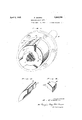
Further objects will appear in the course of the detailed description now to be given with reference to the accompanying drawings, in which Fig. 1 is a phantom view, in perspective, of one illustrative embodiment of the invention;
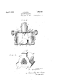
Fig. 2 is a plan of the structure shown in Fig. 1;
Fig. 3 represents, in perspective, the central driving shaft of the assembly;
Fig. 4 shows a floating frictional element; and
Fig. 5 is a ing element.
Referring to the various figures of the drawings, there is shown a driving shaft 1 driven by a motor, pulley, or other suitable mechanism, (not shown) ,--a partially cylindrical block 2 suitably keyed to shaft 1 and including bosses 4 limited at one end by a surface 4 at right angles to the axis of shaft 1, at the other end by oblique plane surfaces, and laterally by a pair of convergent plane surfaces whose function will be pointed out further on,a driven shaft 5,a cylindrical casing rigidly attached to shaft 5 and limited laterally, by a cylindrical wall 6, and longitudinally by a pair of parallel transverse walls 6 and 6 ,a plurality of floating cylindrical segments or shoes 9 interposed between wall 6 and block 2, each shoe being limited by diverging lateral walls 10 and 11 having the same obliquity as the lateral portions of bosses 4,--and floating wedges 14 50 provided with one end surface 14 adapted to coact with surface 6 a second end-surface perspective of a detached Wedg- 14, parallel to, and adapted to slide on one end of a boss 4, and convergent lateral surfaces having the'same obliquity as surfaces 10 and 11. The hereinabove described tions as follows:
Assuming shaft 1' to be driven in the direction of arrow 7' (Fig. 1), the end oblique surface of each boss 4 will exert pressure on corresponding face 14 of each wedge 14 and force the latterin the direction of arrow f- (Figs. land 2) however,because of the obliquity of lateral surfaces 10 and 11 of shoes assembly func- 9, the latter will move radially outward and come into contact with internal cylindrical surface 6; at the same time, while correspond ing ends of each'shoe 9 move into forcible contact withsurface.6 surface 4 is thrust in theopposite direction into frictional contact with surface 6 bosses 4, shoes 9 and wedges 14 thus coact'to, simultaneously effect a locking action in both radial and longitudinal directions which insures very efficient coupling of shafts 1 and 5. When shaft 1 turns in the opposite direction, an inverse series of displacements occur and shafts l and 5 are completely uncoupled.
The use of a plurality of bosses, wedges and shoes permits easier centering of the assembly and their number may be varied at will.
The invention is particularly applicable to pneumatic hammers, to self-startersfor automobile motors, elevators, aeroplanes, etc.
In French Patent No. 652,184, having dlivr date October 22, 1928, to the same inven tor, an apparatus was described for obtaining a unidirectional drive by means of a cam element exerting radial pressure only on a plura-lityoffioatingshoes. Thepresentinvention is an improvement on this prior device in that the radial effect is supplemented by a longitudinal locking action, thus increasing the total area of the frictional surfaces in contact and at the same time insuring a more perfect coupling of the driving and driven shafts.
What I claim is: 1. In combination, adriving shaft, a drivon shaft, a casing having an internal cylindrical wall and an end wall, said casing being rigidly attached to said driven shaft, a plurality of floating shoes interposed between the walls of said casing and the driving shaft,
and a wedge mounted in driven relation to the driving shaft, said wedge being operative by the latter to force said shoes radially and longitudinally into contact with the-internal.- cylindricalhwall and an endiwall of saidr-casr; mg.
19 2. In combination, a driving shaft, a driven shaft, a casing having an 'interna'l-cylin drical wall and an end wall, said casing being v rigidly attached to the driven shaft,"means including; abosslconnected. insdriven relation 15 to the driving shaft, said boss having an oblique :surface ,7 formed: thereon-1 forming: an angle with a plane-:at :rightranglesto the" axis of the driving shaft, a .plurality'of' floating; .1 shoes interposed between said casings-andx the =dPlVTlI1g shaft, :said shoes havinggconvergent lateral surfaces, and a WQClgBQ-QhEL-VlTIgIfCOH-i vergent: lateral; surfaces: and :anzoblitlueeend surfaoe positioned :to contact with the c0rre-,: sponding oblique. surface of 7 said boss, .Sl'ldz;
wedge. being; positioned between said. =.shoes and adjacent amendlwall .of zsaid .-,casing,i: whereby-rotation of: said drivingsshaft :will 1 cause the oblique surfaces :of the wedge-and bossJto slide over one vanother and. bring ,the
convergent lateral surfaces Ofitlle'l'Wedge and. shoesinjcontanti so as do: force;the lateral 1 sur r-; F- faces'radially andlongitudinally intonconei tactrwithithe internalv-wallsof; thex casingn".
M Inutesftmrony whereof: I :have :signed (this i a specifi'cationaz:
ALBERIG? enormi-
Applications Claiming Priority (1)
| Application Number | Priority Date | Filing Date | Title |
|---|---|---|---|
| FR1852735X | 1929-09-18 |
Publications (1)
| Publication Number | Publication Date |
|---|---|
| US1852735A true US1852735A (en) | 1932-04-05 |
Family
ID=9681668
Family Applications (1)
| Application Number | Title | Priority Date | Filing Date |
|---|---|---|---|
| US432312A Expired - Lifetime US1852735A (en) | 1929-09-18 | 1930-09-16 | Unidirectional drive |
Country Status (1)
| Country | Link |
|---|---|
| US (1) | US1852735A (en) |
Cited By (1)
| Publication number | Priority date | Publication date | Assignee | Title |
|---|---|---|---|---|
| US2924086A (en) * | 1958-06-05 | 1960-02-09 | Philco Corp | Drive mechanism |
-
1930
- 1930-09-16 US US432312A patent/US1852735A/en not_active Expired - Lifetime
Cited By (1)
| Publication number | Priority date | Publication date | Assignee | Title |
|---|---|---|---|---|
| US2924086A (en) * | 1958-06-05 | 1960-02-09 | Philco Corp | Drive mechanism |
Similar Documents
| Publication | Publication Date | Title |
|---|---|---|
| US2926034A (en) | Spline coupling | |
| US1852735A (en) | Unidirectional drive | |
| US2835364A (en) | Overrunning clutch | |
| GB2150239A (en) | Freewheel ramp/roller clutch with positive lock-out | |
| US3390748A (en) | Fluid shear coupling | |
| US3237737A (en) | Friction engaging mechanism | |
| CN112377537A (en) | Dual-redundancy bidirectional backstop | |
| US2029244A (en) | Driving mechanism | |
| US1735125A (en) | Ball or roller clutch | |
| US1623236A (en) | Friction clutch | |
| US2551837A (en) | End thrust and torque transmitting coupling | |
| US2378390A (en) | Pump | |
| US2803145A (en) | Transmission mechanism for driving shafts at right angles to each other | |
| US3129797A (en) | Selective drive transmission | |
| US4601601A (en) | Rotary anti-backlash component | |
| US1782605A (en) | Transmission mechanism | |
| US2150468A (en) | Coupling | |
| US907523A (en) | Shaft-coupling. | |
| US3759065A (en) | Keyed joint | |
| US2016849A (en) | Power transmitting apparatus | |
| US1583530A (en) | Clutch mechanism | |
| US1156819A (en) | Clutch. | |
| US2392719A (en) | Clutch | |
| US1544697A (en) | Friction-wheel gear | |
| US1213303A (en) | Power-transmission mechanism. |