US1852734A - Method of gasifying liquid fuel - Google Patents
Method of gasifying liquid fuel Download PDFInfo
- Publication number
- US1852734A US1852734A US241809A US24180927A US1852734A US 1852734 A US1852734 A US 1852734A US 241809 A US241809 A US 241809A US 24180927 A US24180927 A US 24180927A US 1852734 A US1852734 A US 1852734A
- Authority
- US
- United States
- Prior art keywords
- pot
- steam
- converter
- fuel
- liquid fuel
- Prior art date
- Legal status (The legal status is an assumption and is not a legal conclusion. Google has not performed a legal analysis and makes no representation as to the accuracy of the status listed.)
- Expired - Lifetime
Links
Images

Classifications
-
- C—CHEMISTRY; METALLURGY
- C10—PETROLEUM, GAS OR COKE INDUSTRIES; TECHNICAL GASES CONTAINING CARBON MONOXIDE; FUELS; LUBRICANTS; PEAT
- C10G—CRACKING HYDROCARBON OILS; PRODUCTION OF LIQUID HYDROCARBON MIXTURES, e.g. BY DESTRUCTIVE HYDROGENATION, OLIGOMERISATION, POLYMERISATION; RECOVERY OF HYDROCARBON OILS FROM OIL-SHALE, OIL-SAND, OR GASES; REFINING MIXTURES MAINLY CONSISTING OF HYDROCARBONS; REFORMING OF NAPHTHA; MINERAL WAXES
- C10G9/00—Thermal non-catalytic cracking, in the absence of hydrogen, of hydrocarbon oils
- C10G9/34—Thermal non-catalytic cracking, in the absence of hydrogen, of hydrocarbon oils by direct contact with inert preheated fluids, e.g. with molten metals or salts
- C10G9/36—Thermal non-catalytic cracking, in the absence of hydrogen, of hydrocarbon oils by direct contact with inert preheated fluids, e.g. with molten metals or salts with heated gases or vapours
- C10G9/38—Thermal non-catalytic cracking, in the absence of hydrogen, of hydrocarbon oils by direct contact with inert preheated fluids, e.g. with molten metals or salts with heated gases or vapours produced by partial combustion of the material to be cracked or by combustion of another hydrocarbon
-
- F—MECHANICAL ENGINEERING; LIGHTING; HEATING; WEAPONS; BLASTING
- F02—COMBUSTION ENGINES; HOT-GAS OR COMBUSTION-PRODUCT ENGINE PLANTS
- F02M—SUPPLYING COMBUSTION ENGINES IN GENERAL WITH COMBUSTIBLE MIXTURES OR CONSTITUENTS THEREOF
- F02M17/00—Carburettors having pertinent characteristics not provided for in, or of interest apart from, the apparatus of preceding main groups F02M1/00 - F02M15/00
- F02M17/18—Other surface carburettors
- F02M17/26—Other surface carburettors with other wetted bodies
Definitions
- Patented Apr. 5, 1932 are PHILIP liIASON CABELL, OF NEW YORK, N. Y.
- This invention relates to a method of converting liquid fuel into fixed combustible gas.
- a liquid fuel such as kerosene, gas oil, fuel oil, or other heavy oil, or other relatively non-volatile liquid fuel
- a liquid fuel is converted into fixed combustible gas by vaporizing it and heating it in the presence of steam to a temperature sull'lcient to crack the oil and to dissociate the
- This operation takes place in a converter whicn is maintained at the required temperature by partial combustion of the fuel therein.
- a suction device is used to draw gas from the converter and to maintain a sub-atmospheric pressure in the converter which is utilized to draw fuel into the converter and to draw air into the converter to support partial combustion therein.
- Steam is supplied to the converter.
- a feature of the ll *ention consists in limiting the combustion to a desired part of the converter and in extending the zone of combustion, by introducing steam into the converter at a rate which may be regulated.
- Fig. 1 is a diagrammatic side elevation of the complete apparatus
- Fig. 2 is a vertical section of the converter sectioned on the line 22 of Fig. 8;
- Fig. 3 is an enlarged vertical section of the upper part of the converter, with parts removed, taken on the line 2-? of Fig. 8, and showing the oil and air inlets;
- Fig. 4 is a vertical sectional view of the valve through which the steam is admitted to the converter
- Fig. 5 is a partial vertical section of the converter, taken on the line 5 5 of Fig. 8, and showing the pyromcter and the gas outlet from the converter;
- Fig. (3 is a top View of the converter, omit- Divided and this application filed December Renewed August 23, 1931.
- Fig. 7 is a fragmentary horizontal section on the line 7-7 of Fig. 3, showing the air inlet;
- jl ig. 8 is a horizontal section of the conver er on the line 88 of Figs. 2 and 5 5 and Fig. 9 is a side elevation of the cut-off valve between the starting lamp and the converter.
- the general arran ement of the apparatus is shown in Fig. 1.
- the system as shown includes an internal combustion engine, indicated diagrammatically at E, and a converter C.
- the engine may be of any ordinary gas or gasoline type.
- the intake manifold E1 of the engine is connected by piping 10 to the gas outlet of the converter C.
- the suction of the engine produces a partial vacuum in the converter C which draws air into the converter through a pipe 13.
- the outer end of this air supply pipe communicates with a heater 14 which surrounds a portion of the exhaust pipe E2 of the engine.
- the liquid fuel is fed by gravity from a tank 15 to a float chamber 16 through a fuel supply pipe 17. From the float chamber 16 the fuel is drawn into the converter by the partial vacuum in the converter aided and modified by air flow through the Venturi inlet hereinafter described.
- the supply of oil in the tank 15 may be maintained by pumping oil into the tank from a storage tank (not shown in the drawings) by means of a pump 20 driven by the engine E.
- An overflow pipe 21 leads from the upper part of the tank 15 to the storage tank.
- Waste heat is utilized to furnish steam to the converter.
- Such waste heat may be taken from the exhaust gases of the engine.
- a flash boiler B formed of a coil of pipe, is placed in a casing 23 tl'irough which the exhaust gases from the engine E pass after they leave the heater 14.
- lYater is supplied to the flash boiler from a water tank 24 through a pipe 25.
- the steam formed in the flash boiler B passes through a pipe 26 to an expansion chamber 27 and thence through a pipe 28 into the converter C.
- a part of the steam may be passed through a pipe 29 branching from the pipe 28 into a heater 3O surrounding part of the fuel pipe 17.
- the pipe 29 contains a valve 31 which need be opened only in case the liquid fuel used is so heavy or viscid that it is desirable to heat it to make it more fluid.
- the apparatus illustrated in Fig. 1 thus forms a complete system for converting liquid fuel into a fixed gas and utilizing this fuel to produce mechanical power.
- the internal combustion engine operates merely as a suction device serving to draw from the converter at the rate at which it is desired to use the gas.
- the converter C has in the apparatus shown the form of a vertical cylinder. It has an outer insulated wall C1 and an insulated bottom C2. ⁇ Vithin the wall C1 and spaced therefrom is a cylindrical pot C3 which is open at the bottom and has a metal cylindrical wall C4 protected by inner and outer facings C5, C6, of refractory material. The pot C3 is suspended in the converter by an outwardly extending flange C7 formed at the top of the cylindrical wall C4 of the pot and resting in a recess at the top inner edge of the outer wall C1.
- the pot C3 In the pot C3 are a series of horizontal foraminous trays or screens C10, C12, C13. On these trays are permeable and absorbent beds on layers C14, C16, C17, of refractory material.
- the beds are most desirably formed of small pieces of porous and absorbent refractory material, such as broken crucible material, known commercially as pot, and composed principally of clay and graphite. Broken pieces of such absorbent porous refractory material are better for the purpose than balls or other molded or natural pieces.
- the refractory material C14 on the upper tray C10 is arranged in a circular mass in the central portion of the tray so as to leave an unobstructed annular space surrounding its periphery.
- the refractory material C16 on the next tray C12 is arranged on the outer portion of the tray so as to leave an unobstructed relatively small central opening.
- the layers C17 of refractory material are arranged alternately in the central portion of the tray, and in the outer portion of the tray.
- a deflector or spreader C18 formed of a molded mass of refractory material having an upper deflecting surface C19 which is convex and spherically curved.
- the deflector is best provided with a plurality of small vertical holes C18a for permitting some of the liquid fuel to pass through the deflector to the part of the permeable bed C14 below it.
- the trays may be spaced uniformly in the body, except that the space C20 between the trays C10 and C12 is desirably lar 'er than the space between the other trays.
- the top of the converter is closed by a cover plate C30 which contains a central opening C31 through which air, liquid fuel and steam are introduced into the pot C3.
- a cylindrical flange C32 extends upwardly around this opening C31 and a higher cylindrical flange C33 extends upwardly outside the flange C32.
- a cover C34 is secured to the upper end of the outer flange C33.
- the cover plate C30 and the cover C34 are cov ered with insulating material C35 which is confined by an outer casing C36.
- the air pipe 13 communicates with an inlet opening C37 in the flange C33, so that air is drawn into the annular space between the flanges C32 and C33, over the inner flange C32 and down into the pot C3 through the central opening C31 in the cover plate 30.
- the flow of air into the pot is regulated by a valve C40 at the top of the flange C32.
- This valve includes a fixed shutter C41 and a movable shutter C42 having a hollow stem C43 which extends through central openings in the cover C34 and the casing C36.
- a handle C44 is fixed on this hollow stem outside the casing C36.
- a Venturi tube C through which the air passes in entering the pot C3.
- the reduction in the pressure of the air at the throat of this Venturi tube, concomitant with the increase in the velocity of the air at this point, is utilized in drawing the liquid fuel into the pot 13 from the float chamber 16.
- the float chamber is connected by a pipe C51 with an annular passage C52 surrouiuling the throat of the Vcnturi tube C50 and communicating therewith through transverse holes C53.
- the holes C53 are located slightly above the liquid level maintained in the float chamber 16 so that no fuel flows into the pot except when there is a subatmospheric pressure in the throat of the Venturi tube.
- a valve C54 in the pipe C51 provides an adjustable restriction for controlling the amount of liquid fuel drawn into the converter.
- the amount drawn in depends on the pressure reduction in the Venturi throat and on the adjustment of the valve, and in the operation of the converter the fuel supply varies automatically according to the suction applied to the converter, that is the amount of gas required. as hereinafter described. 7 i
- the nozzle pipe C61 is threaded at its upper end and screwed into the lower end of the hollow stem C43, so that it may easily be detached.
- the effective area of the throat of the Venturi tube C may be varied to adapt the converter for most efficient use in connection with internal combustion engines of different sizes, or to adapt the Venturi tube for use in converters of different capacity within limits.
- the gas which is drawn out of the bottom of the pot C3 through the central opening in the refractory material on the lowest tray is directed upwardly by a horizontal partition C65 extending across the converting chamber below the pot.
- the gas passes up through the cylindrical space between the pot C3 and the wall Cl and thence into the pipe 10 which communicates with said cylindrical space through the wall C1 near the top thereof.
- the converter may be provided with a pyrometer C having a rod C71 extending into the cylindrical space between the outer wall C1 and the pot C3, and with a peep hole C72 extending through the casing C36, the insulation C35 and the cover plate C30, and having a glass C73 through which the upper portion of the pot chamber is visible.
- FIG. 1 shows a high temperature in the pot C3 by partial combustion of the fuel and other reactions taking place therein.
- the converter In order to start the operation of the converter it is necessary to heat a portion of it to a temperature above the vaporization temperature of the liquid fuel.
- the drawings show means for such initial heating by the supply of heat di- I rectly to the interior of the converting chamber.
- such means includes a conduit C7 5 leading to an opening C76 in the wall of the pot C3 between the most widely spaced trays C10 and C12 and extending upward through the cover plate C30 and then horizontally outward.
- Near its outer end is a slide valve C77.
- the slide valve C77 is provided with a frame C77a to prevent it from warping.
- This frame is wider at the top than at the bottom. and the valve fits in a downwardly tapering slot C775 formed at the outer end of the conduit C75.
- I provide a slide valve which may be operated quickly and which always fits tightly.
- a wick C78 of refractory material to which liquid fuel is supplied from a cup C79. Liquid fuel may be supplied to this cup through a pipe 33 branching from the fuel pipe 17 and provided with a valve 34.
- a lamp, or small liquid fuel receptacle C80 In the outer end of the conduit C7 5 is a lamp, or small liquid fuel receptacle C80.
- the lamp C80 rests on a tray C80a provided with a drain pipe C8012 to lead off any oil which may be spilled from the lamp.
- An upwardly directed chimney C81, forming a continuation of the conduit, is provided above the lamp, and a shutter C82 normally closes a lighting opening adjacent the lamp.
- check valves C83, C84, C85 are provided in the annular air passage between the flanges C32 and C33, in the conduit C75, and in the oil pipe C51 respectively.
- the check valve C84 in the conduit C7 5 is of peculiar construction and constitutes a part of my invention. This check valve comprises two plates C84a, C846, which extend at a fixed angle to each other.
- the valve is hinged in the conduit C75 in such manner that the plate C84a normally extends across the conduit, resting against a stop as shown, while the plate C84?) is inclined inwardly from the plate C84a.
- the plate C8401. contains an opening C840 through which the flame from the starting lamp C80 may be drawn into the pot.
- the gas starting to flow out through the conduit C75 swings the valve so as to bring the plate C84?) across the conduit and against the stop. The valve is, therefore, closed with great rapidity.
- a liquid residue may flow from the bottom of the pot C3 and collect on the partition C65.
- a valve C86 is provided in the partition C65 and a drain pipe C87 provided with a valve C88 is connected to the bottom of the converter.
- An air inlet C89 controlled by a valve C90 permits the admission of air to the lower portion of the converter, after the valve C86 has been closed, so that the residue trapped in the lower part of the con- EerYter may flow out through the drain pipe
- the steam which is supplied to the converter through the pipe 28 has several important functions which are hereinafter explained. In order to perform these func- Ill;
- the steam be supplied at a rate which may be closely regulated and under a uniform pressure.
- the drawings illustrate a means for supplying steam under a uniform pressure which forms the subject matter of my Patent No. 1,737,826, dated December 3, 1929. According to the invention claimed in that patent the supply of steam under uniform pressure is obtained by providing a flash boiler and maintaining the water supplied to the boiler under a pressure equal to the steam pressure desired and admitting the water to the boiler through a passage so constructed that steam and water cannot pass through it in opposite directions.
- the water in the tank 24 is maintained under a uniform pressure by pumping air into the top of this tank through a pipe 35.
- a hand pump 36 may be provided for this purpose.
- the hand pump need be operated only occasionally in order to maintain the desired pressure in the tank 24.
- the water goes through a U-shaped pipe B1 and a constricted passage in a needle valve B2, both inserted in the pipe 25 near the boiler.
- the flash boiler B is maintained heated to a temperature well above the boiling point of water by the heat of the exhaust gases which pass through the easing 23. ⁇ Vhen the boiler has been heated, the needle valve B2 is opened sufiiciently to permit a slow flow of water under the pressure maintained in the tank 24. As soon any water enters the boiler B through the needle valve B2, this water is converted into steam, creating a pressure in the boiler. If this pressure is equal to or greater than that maintained in the tank 24, it prevents a further flow of water through the needle valve B2.
- the U-shaped pipe Bl prevents steam from the boiler B from passing back through the pipe lVhen the steam consumption is small, it is possible to omit the U-shaped pipe B1, and to rely on the needle valve B2 to prevent back flow of the steam.
- the steam is supplied under approximately constant pressure to the needle valve C60.
- the rate of flow of the steam into the converter remains constant for any given setting of the needle valve C60. Th rate may, however, be varied by adjustment of this needle valve, and the boiler will supply the amount of steam required.
- the engine E is first operated in the usual manner by means of volatile fuel, such as gasolene, supplied through a pipe 38 to a carburetor E3 connected with the intake manifold E1 of the engine. Sufiicient air to form a proper mixture is admitted by adjustment of the carburetor air valve E4.
- the starting lamp C80 is lighted, oil is supplied to the Wick C78 from the cup C79, and the slide valve C77 is opened, the shutter C82 having first been closed in order to avoid possible harm to the operator if there should be an explosion when the valve C77 is opened.
- a valve 39 in the gas pipe 10 through which the fuel gas flows from the converter to the engine, is then partly opened and the carburetor air valve is closed a little.
- T he valve C54 is gradually opened during this rise in temperature and may be opened sufiiciently to supply oil at a rate sufficient for the normal operation of the converter when the temperature indicated on the pyrometer reaches 450 F.
- the needle valve C60 is opened slightly more during the rise in temperature in the pot, suiiiicent steam being admitted to prevent combustion from taking place above the upper tray C10.
- the air valve C40 is closed somewhat and set so as to permit only sufficient combustion to maintain the desired indication by the pyrometer of the temperature of the outflowing gases in the space between the inner and outer casings of the converter. It has been found best to maintain this temperature at about 800 F., but the most desirable temperature to be maintained will vary with conditions and according to the design of the converter, and may vary within quite wide limits for a given converter.
- the valve 39 is opened more and more.
- the supply of gasolene to the carburetor E2 may be shut off by closing a valve 41 in the pipe 38, and the valves 89 and E4 are adjusted so that sufiicient air is drawn in through the valve E4 to form an explosive mixture with the gas drawn into the intake manifold from the pipe 10.
- the fuel gas passing from the converter has a large content of methane and illuminants, giving it a high B. t. 11. value, and also a smaller content of uncombined hydrogen and uncombined oxygen.
- the gas is a clean gas requiring no scrubbing before use in the engine.
- the liquid fuel which is drawn into the pot through the Venturi tube drips upon the distributor C18 and is spread out by the distributor so that it permeates evenly into the upper bed C14 and spreads over its extended surface, some of the liquid being absorbed in the refractory material of the bed.
- Part of the liquid fuel is vaporized in the bed C14, while a considerable portion of the fuel drips down from the bed C14. and unvaporized portions of the liquid fuel thus pass downward from bed to bed, spreading over the extended surface of successive beds and being absorbed to some extent in the refractory material of the beds.
- the fuel vapor flows downward through the tortuous pasage with the air and steam, and combustion takes place below the tray C10 and, most desirably, below the space C20.
- the heat of this combustion vaporizes the liquid fuel spread over and absorbed in the refractory material of the beds.
- the air supplied is suflicient for complete oxidization of only a part of the carbon contained in the fuel
- the partial combustion raises the lower part of the pot to flame temperature.
- the temperature is such that the fuel is cracked, that is, the heavy hydrocarbons in it are split up into lighter hydrocarbons.
- the steam is decomposed into oxygen and hydrogen. Both these elements combine with carbon from the fuel.
- the steam which is introduced into the pot has several important functions:
- dissociating In dissociating, it furnishes nascent oxygen and hydrogen which combine with free carbon present in the pot, including any soot which might otherwise be deposited in the refractory material on the trays in starting the operation of the pot.
- the steam is supplied in amount sufficient not only to insure oxidization of all free carbon formed in the pot, but also to leave some free oxygen in the gas which is withdrawn from the pot. It. therefore, effectively prevents deposition of carbon within the pot.
- the steam prevents combustion in the upper part of the pot, especially in the space above the upper bed C14. This I believe to be due, principally at least, to the fact that the steam dilutes the mixture of liquid fuel vapor and air so as to prevent the formation of an inflammable mixture at and near the top of the pot.
- the extent to which the zone of combustion is depressed depends upon the The rapid flow of the stream a through each central opening tends to throw 1 relative amount of steam introduced. I have found it desirable to introduce such a relative amount of steam that combustion does not take place for some distance below the upper bed.
- the steam also serves to extend the zone of combustion within the pot, and this is of great advantage in securing more complete cracking of the fuel and increasing the producing capacity of the pot. admitting suilicient steam, the combustion may be made to begin at any desired distance below the upper bed C14, and the zone of combus tion may be made to extend well down toward or to the bottom of the pot.
- the upper eds are maintained at a comparatively low temperature and trouble from the formation of carbon is thus avoided.
- the maintenance of sub-atmospheric pressure in the pot has important advantages. It makes it possible to draw in the air and the fuel by a suction which varies with the rate at which the gas is used, so that the rate of supply both of the air and of the liquid fuel varies automatically with changes in the rate at which the gas is used. Furthermore, since the supply of liquid fuel depends on the maintenance of a sub-atmospheric pressure in the pot, the rate at which the fuel is supplied even in full capacity operation of the converter automatically regulated. This is because, if an excess of liquid fuel is drawn into the pot, the rapid vaporization of this liquid fuel decreases the degree of vacuum in the pot and in consequence checks the sup ply of fuel to the pot.
- the method of producing fixed fuel gas which comprises supplying liquid fuel conti nuously to the upper one of a series of heated superposed spaced permeable baffles of refractory material arranged in a converting chanil er so as to provide a free tortuous and generally downward passage from the top of said chamber past and between the baffles, whereby unvz-iporized portions of the liquid fuel are caused to pass downward from the upper baflle and from bafile to baffle to be gradually vaporized; admitting air to the converting chamber above the upper baffle in quantity sufiicient for combustion of a small part of the fuel vapor, and supplying steam to the converting chamber above the upper baflle in quantity sufficient to depress and extend the zone of combustion, and applying suction to the lower end of the converting chamber, whereby the air and steam are caused to flow downward through the passage taking up and becoming mixed with the fuel vapor and combustion is prevented in the upper portion of said passage; and causing partial combustion to take place
- the method of producing fixed fuel gas which comprises continuously supplying liquid fuel to heated absorbent refractory material located along a. free tortuous passage; supplying to the entrance end of said passage air in quantity sufficient for combustion of a small part of the fuel vapor and steam in quantity sufficient to prevent combustion near the entrance end of said passage, and maintaining a pressure difference between the ends of the passage, whereby the air, steam and fuel vapor are caused to flow through the passage; and then converting the unburned fuel vapor into fixed gas and decomposing steam to cause the consumption of free carbon and to increase the amount and total heat value of the gas produced from a unit amount of liquid fuel by subjecting the mixed air, steam and fuel vapor to high heat resulting from partial combustion of the fuel vapor.
- the method of producing fixed fuel gas which comprises continuously supplying liquid fuel to heated absorbent refractory material in a vaporizing zone of a convert ing chamber, passing a stream of air and steam past the surface of said material to take up the fuel vapor, the air being in quantity sufficient for combustion of only a small part of the fuel vapor taken up and the steam being in quantity sufficient to prevent combustion in the vaporizing zone, mixing the air, steam and fuel vapor, and causing partial combustion to take place in a gasifying zone of the converting chamber, whereby heat is produced to convert unburned fuel vapor into fixed gas and to decompose steam to cause the consumption of free carbon and to increase the amount and total heat value of the gas produced from a unit amount of liquid fuel.
- the method of producing fixed fuel gas which comprises supplying liquid fuel continuously to a converting chamber having baffles arranged therein to provide a free tortuous flow passage, the baflies forming the first part of said How passage being superposed spaced permeable beds of absorbent refractory material; distributing the liquid fuel on the upper bed and maintaining said beds at a relatively low temperature, whereby as liquid fuel passes downward through the upper bed and from bed to bed it will be gradually vapo ized applying suction to the converting chamber to draw the fuel vapor downward through said passage past said vaporizing beds and into a gasifying zone of the converting chamber and to maintain a sub-atmospheric pres ure in the converting chamber; admitting air in quantity sufficient for combustion of a small part of the fuel vapor to burn some of the fuel vapor in the gasifying zone, thereby causing the production of heat to convert unburned fuel vapor into fixed gas; and supplying steam to be decomposed in the gasifying zone to consume free carbon and to in crease the amount and total heat
- the method of producing fixed fuel gas which comprises supplying liquid fuel continuously to a converting chamber having bafiies arranged therein to provide a free tortuous flow passage, the bafiies forming the first part of said flow passage being superposed spaced permeable beds of absorbent refractory material; distributing the liquid fuel on the upper bed and maintaining said beds at a relatively low temperature, whereby as liquid fuel passes downward through the upper bed and from bed to bed it ill be gradually vaporized; applying suction to the converting chamber to draw the fuel vapor downward through said passage past said vaporizing beds and into a gasifying zone of the converting chamber and to maintain a sub-atmospheric pressure in the converting chamber; admitting air to the converting chamber above the upper bed in quantity sufficient for combustion of a small part of the fuel vapor; and supplying steam to the converting chamber above the upper bed in quantity adequate to prevent combustion in the upper part of the chamber and to extend the zone of combustion in the gasifying zone, the heat produced in the gasifying zone converting unburned fuel
- the method of producing fixed fuel gas which comprises continuously supplying liquid fuel to heated absorbent refractory material located along a free tortuous passage in a converting chamber; supplying air to the entrance end of said passage in quantity sufficient for combustion of a small part of the fuel vapor; maintaining a pressure difference between the ends of the passage whereby the air and the fuel vapor are caused to flow to a gasifying zone of the converting chamber, and supplying steam to the en trance end of said passage in quantity sufficient to prevent combustion near the entrance end of said passage and to extend the zone of combustion in the gasifying zone of the converting chamber.
Description
April 5, 1932. P. M. CABELL METHOD OF GASIFYING LIQUID FUEL Original Filed July 17, 1923 3 Sheets-Sheet l INVENTOR 1; ATTdRNEY April 5, 1932. P. M. CABELL 1,852,734
METHOD OF GASIFYING LIQUID FUEL Original Filed July 17, 1923 5 Sheets-Sheet 2 l-l ATTORNEY 1 f 7 3 w a 3% 3.1 4 i 0 MM/V, N ry ll 0 1/ W W 1% L 4 w 0 2 Z o 7 u 7 v a m aw a m 1 a April'5, 1932. P. M. cABELL um'non OF GASIF'YING LIQUID FUEL Original Filed July 17, 1923 3 ShGGtS-ShGGt 3 INVENT R ATTOF'QNEY steam.
Patented Apr. 5, 1932 are PHILIP liIASON CABELL, OF NEW YORK, N. Y.
METHOD OF GASIFYING LIQUID FUEL Original application filed July 17, 1923, Serial No. 652,011.
Serial No. 241,809.
This invention relates to a method of converting liquid fuel into fixed combustible gas.
In accordance with the invention, a liquid fuel, such as kerosene, gas oil, fuel oil, or other heavy oil, or other relatively non-volatile liquid fuel, is converted into fixed combustible gas by vaporizing it and heating it in the presence of steam to a temperature sull'lcient to crack the oil and to dissociate the This operation takes place in a converter whicn is maintained at the required temperature by partial combustion of the fuel therein. A suction device is used to draw gas from the converter and to maintain a sub-atmospheric pressure in the converter which is utilized to draw fuel into the converter and to draw air into the converter to support partial combustion therein. Steam is supplied to the converter. A feature of the ll *ention consists in limiting the combustion to a desired part of the converter and in extending the zone of combustion, by introducing steam into the converter at a rate which may be regulated.
Other features and advantages of the invention are hereinafter set forth in connection with a detailed description of a method of producing fixed gas in accordance with the invention, and practical apparatui-a for carrying out such method. Such apparatus may be used as part of a complete apparatus for producing mechanical power from liquid fuel and is so shown in the accompanying drawings, in which:
Fig. 1 is a diagrammatic side elevation of the complete apparatus;
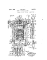
Fig. 2 is a vertical section of the converter sectioned on the line 22 of Fig. 8;
Fig. 3 is an enlarged vertical section of the upper part of the converter, with parts removed, taken on the line 2-? of Fig. 8, and showing the oil and air inlets;
Fig. 4 is a vertical sectional view of the valve through which the steam is admitted to the converter;
Fig. 5 is a partial vertical section of the converter, taken on the line 5 5 of Fig. 8, and showing the pyromcter and the gas outlet from the converter;
Fig. (3 is a top View of the converter, omit- Divided and this application filed December Renewed August 23, 1931.
ting the steam supply pipe and needle valve;
Fig. 7 is a fragmentary horizontal section on the line 7-7 of Fig. 3, showing the air inlet;
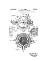
jl ig. 8 is a horizontal section of the conver er on the line 88 of Figs. 2 and 5 5 and Fig. 9 is a side elevation of the cut-off valve between the starting lamp and the converter.
The general arran ement of the apparatus is shown in Fig. 1. The system as shown includes an internal combustion engine, indicated diagrammatically at E, and a converter C. The engine may be of any ordinary gas or gasoline type. The intake manifold E1 of the engine is connected by piping 10 to the gas outlet of the converter C. The suction of the engine produces a partial vacuum in the converter C which draws air into the converter through a pipe 13. The outer end of this air supply pipe communicates with a heater 14 which surrounds a portion of the exhaust pipe E2 of the engine. The liquid fuel is fed by gravity from a tank 15 to a float chamber 16 through a fuel supply pipe 17. From the float chamber 16 the fuel is drawn into the converter by the partial vacuum in the converter aided and modified by air flow through the Venturi inlet hereinafter described.
The supply of oil in the tank 15 may be maintained by pumping oil into the tank from a storage tank (not shown in the drawings) by means of a pump 20 driven by the engine E. An overflow pipe 21 leads from the upper part of the tank 15 to the storage tank.
Waste heat is utilized to furnish steam to the converter. Such waste heat may be taken from the exhaust gases of the engine. In order to utilize it, a flash boiler B, formed of a coil of pipe, is placed in a casing 23 tl'irough which the exhaust gases from the engine E pass after they leave the heater 14. lYater is supplied to the flash boiler from a water tank 24 through a pipe 25. The steam formed in the flash boiler B passes through a pipe 26 to an expansion chamber 27 and thence through a pipe 28 into the converter C. A part of the steam may be passed through a pipe 29 branching from the pipe 28 into a heater 3O surrounding part of the fuel pipe 17. The pipe 29 contains a valve 31 which need be opened only in case the liquid fuel used is so heavy or viscid that it is desirable to heat it to make it more fluid.
The apparatus illustrated in Fig. 1 thus forms a complete system for converting liquid fuel into a fixed gas and utilizing this fuel to produce mechanical power. So far as the present invention is concerned the internal combustion engine operates merely as a suction device serving to draw from the converter at the rate at which it is desired to use the gas.
The converter C has in the apparatus shown the form of a vertical cylinder. It has an outer insulated wall C1 and an insulated bottom C2. \Vithin the wall C1 and spaced therefrom is a cylindrical pot C3 which is open at the bottom and has a metal cylindrical wall C4 protected by inner and outer facings C5, C6, of refractory material. The pot C3 is suspended in the converter by an outwardly extending flange C7 formed at the top of the cylindrical wall C4 of the pot and resting in a recess at the top inner edge of the outer wall C1.
In the pot C3 are a series of horizontal foraminous trays or screens C10, C12, C13. On these trays are permeable and absorbent beds on layers C14, C16, C17, of refractory material. The beds are most desirably formed of small pieces of porous and absorbent refractory material, such as broken crucible material, known commercially as pot, and composed principally of clay and graphite. Broken pieces of such absorbent porous refractory material are better for the purpose than balls or other molded or natural pieces. The refractory material C14 on the upper tray C10 is arranged in a circular mass in the central portion of the tray so as to leave an unobstructed annular space surrounding its periphery. The refractory material C16 on the next tray C12 is arranged on the outer portion of the tray so as to leave an unobstructed relatively small central opening. On the remaining trays C13 the layers C17 of refractory material are arranged alternately in the central portion of the tray, and in the outer portion of the tray. It is apparent that the arrangement of the refractory material which has been described provides a series of permeable loafiles each of which has an extended surface of absorbent porous material and which leave a free but tortuous flow passage of min-uniform cros section from the top of the pot to the bottom thereof.
On the layer C14 of refractory material on the upper tray C10 is placed a deflector or spreader C18 formed of a molded mass of refractory material having an upper deflecting surface C19 which is convex and spherically curved. The deflector is best provided with a plurality of small vertical holes C18a for permitting some of the liquid fuel to pass through the deflector to the part of the permeable bed C14 below it.
The trays may be spaced uniformly in the body, except that the space C20 between the trays C10 and C12 is desirably lar 'er than the space between the other trays.
The top of the converter is closed by a cover plate C30 which contains a central opening C31 through which air, liquid fuel and steam are introduced into the pot C3. A cylindrical flange C32 extends upwardly around this opening C31 and a higher cylindrical flange C33 extends upwardly outside the flange C32. A cover C34 is secured to the upper end of the outer flange C33. The cover plate C30 and the cover C34 are cov ered with insulating material C35 which is confined by an outer casing C36.
The air pipe 13 communicates with an inlet opening C37 in the flange C33, so that air is drawn into the annular space between the flanges C32 and C33, over the inner flange C32 and down into the pot C3 through the central opening C31 in the cover plate 30. The flow of air into the pot is regulated by a valve C40 at the top of the flange C32. This valve includes a fixed shutter C41 and a movable shutter C42 having a hollow stem C43 which extends through central openings in the cover C34 and the casing C36. A handle C44 is fixed on this hollow stem outside the casing C36.
Within the flange is placed a Venturi tube C through which the air passes in entering the pot C3. The reduction in the pressure of the air at the throat of this Venturi tube, concomitant with the increase in the velocity of the air at this point, is utilized in drawing the liquid fuel into the pot 13 from the float chamber 16. For this purpose the float chamber is connected by a pipe C51 with an annular passage C52 surrouiuling the throat of the Vcnturi tube C50 and communicating therewith through transverse holes C53. The holes C53 are located slightly above the liquid level maintained in the float chamber 16 so that no fuel flows into the pot except when there is a subatmospheric pressure in the throat of the Venturi tube.
A valve C54 in the pipe C51 provides an adjustable restriction for controlling the amount of liquid fuel drawn into the converter. The amount drawn in depends on the pressure reduction in the Venturi throat and on the adjustment of the valve, and in the operation of the converter the fuel supply varies automatically according to the suction applied to the converter, that is the amount of gas required. as hereinafter described. 7 i
The steam. which is supplied through the pipe 28, passes through a needle valve C mounted on the upper end of the hollow stem C43. From this valve the steam passes through the hollow stein C43 into a nozzle pipe C61 which extends down through the middle of the Venturi tube C50 and has at its lower end an outlet opening C62 located near the lower end of the Venturi tube and directed toward the center of the deflecting surface C19 of the spreader C18. The nozzle pipe C61 is threaded at its upper end and screwed into the lower end of the hollow stem C43, so that it may easily be detached. By substituting for the nozzle pipe C61 a similar nozzle pipe having a different external diameter, the effective area of the throat of the Venturi tube C may be varied to adapt the converter for most efficient use in connection with internal combustion engines of different sizes, or to adapt the Venturi tube for use in converters of different capacity within limits.
The gas which is drawn out of the bottom of the pot C3 through the central opening in the refractory material on the lowest tray is directed upwardly by a horizontal partition C65 extending across the converting chamber below the pot. The gas passes up through the cylindrical space between the pot C3 and the wall Cl and thence into the pipe 10 which communicates with said cylindrical space through the wall C1 near the top thereof.
For convenience in operation, the converter may be provided with a pyrometer C having a rod C71 extending into the cylindrical space between the outer wall C1 and the pot C3, and with a peep hole C72 extending through the casing C36, the insulation C35 and the cover plate C30, and having a glass C73 through which the upper portion of the pot chamber is visible.
During the operation of the converter a high temperature is maintained in the pot C3 by partial combustion of the fuel and other reactions taking place therein. In order to start the operation of the converter it is necessary to heat a portion of it to a temperature above the vaporization temperature of the liquid fuel. The drawings show means for such initial heating by the supply of heat di- I rectly to the interior of the converting chamber. As shown, such means includes a conduit C7 5 leading to an opening C76 in the wall of the pot C3 between the most widely spaced trays C10 and C12 and extending upward through the cover plate C30 and then horizontally outward. Near its outer end is a slide valve C77. The slide valve C77 is provided with a frame C77a to prevent it from warping. This frame is wider at the top than at the bottom. and the valve fits in a downwardly tapering slot C775 formed at the outer end of the conduit C75. By this construction, I provide a slide valve which may be operated quickly and which always fits tightly. In the conduit C beyond the valve C77 is a wick C78 of refractory material to which liquid fuel is supplied from a cup C79. Liquid fuel may be supplied to this cup through a pipe 33 branching from the fuel pipe 17 and provided with a valve 34. In the outer end of the conduit C7 5 is a lamp, or small liquid fuel receptacle C80. The lamp C80 rests on a tray C80a provided with a drain pipe C8012 to lead off any oil which may be spilled from the lamp. An upwardly directed chimney C81, forming a continuation of the conduit, is provided above the lamp, and a shutter C82 normally closes a lighting opening adjacent the lamp.
The parts of the converter which have been described are sufficient for its successful operation. In order, however, to render the converter more nearly fool-proof, it is provided with certain features which are of use in case of careless or incorrect operation of it.
If too much air is admitted to the converter, an explosive mixture may be formed in the upper part of the pot, and this mixture, in igniting suddenly, may momentarily raise the pressure in the pot above atmospheric pressure. In order to prevent a back flow of gases, should this occur, check valves C83, C84, C85, are provided in the annular air passage between the flanges C32 and C33, in the conduit C75, and in the oil pipe C51 respectively. The check valve C84 in the conduit C7 5 is of peculiar construction and constitutes a part of my invention. This check valve comprises two plates C84a, C846, which extend at a fixed angle to each other. The valve is hinged in the conduit C75 in such manner that the plate C84a normally extends across the conduit, resting against a stop as shown, while the plate C84?) is inclined inwardly from the plate C84a. The plate C8401. contains an opening C840 through which the flame from the starting lamp C80 may be drawn into the pot. In case of an accidental rise in pressure in the pot, the gas starting to flow out through the conduit C75 swings the valve so as to bring the plate C84?) across the conduit and against the stop. The valve is, therefore, closed with great rapidity.
If the converter is operated at too low a temperature, or with the zone of combustion not extending far enough down in it, a liquid residue may flow from the bottom of the pot C3 and collect on the partition C65. To permit the removal of such a residue from the converter, a valve C86 is provided in the partition C65 and a drain pipe C87 provided with a valve C88 is connected to the bottom of the converter. An air inlet C89 controlled by a valve C90 permits the admission of air to the lower portion of the converter, after the valve C86 has been closed, so that the residue trapped in the lower part of the con- EerYter may flow out through the drain pipe The steam which is supplied to the converter through the pipe 28 has several important functions which are hereinafter explained. In order to perform these func- Ill;
tions efliciently, it is desirable that the steam be supplied at a rate which may be closely regulated and under a uniform pressure. The drawings illustrate a means for supplying steam under a uniform pressure which forms the subject matter of my Patent No. 1,737,826, dated December 3, 1929. According to the invention claimed in that patent the supply of steam under uniform pressure is obtained by providing a flash boiler and maintaining the water supplied to the boiler under a pressure equal to the steam pressure desired and admitting the water to the boiler through a passage so constructed that steam and water cannot pass through it in opposite directions.
The water in the tank 24 is maintained under a uniform pressure by pumping air into the top of this tank through a pipe 35. A hand pump 36 may be provided for this purpose. As the tank may be large compared to the amount of water consumed, the hand pump need be operated only occasionally in order to maintain the desired pressure in the tank 24. In passing from the tank 24 to the boiler B through the pipe 25, the water goes through a U-shaped pipe B1 and a constricted passage in a needle valve B2, both inserted in the pipe 25 near the boiler.
In operation, the flash boiler B is maintained heated to a temperature well above the boiling point of water by the heat of the exhaust gases which pass through the easing 23. \Vhen the boiler has been heated, the needle valve B2 is opened sufiiciently to permit a slow flow of water under the pressure maintained in the tank 24. As soon any water enters the boiler B through the needle valve B2, this water is converted into steam, creating a pressure in the boiler. If this pressure is equal to or greater than that maintained in the tank 24, it prevents a further flow of water through the needle valve B2. The U-shaped pipe Bl prevents steam from the boiler B from passing back through the pipe lVhen the steam consumption is small, it is possible to omit the U-shaped pipe B1, and to rely on the needle valve B2 to prevent back flow of the steam. The smaller the passage through the needle valve B2, the more completely will it prevent the passage of the steam through it past the water.
When by condensation, or consumption, of the steam formed in the boiler, the pressure in the boiler falls somewhat below that main tained in the tank, additional water enters the boiler slowly through the needle valve and flashes into steam. again raising the pressure in the boiler. I have found that while the pressure of the steam in the boiler oscillates somewhat, it remains always approximately equal to the pressure maintained in the tank 24. The oscillations of steam pressure are damped out in the expansion chamber 27, so
that the steam is supplied under approximately constant pressure to the needle valve C60. As this pressure remains constant, the rate of flow of the steam into the converter remains constant for any given setting of the needle valve C60. Th rate may, however, be varied by adjustment of this needle valve, and the boiler will supply the amount of steam required.
The use of the apparatus which has been described is as follows:
In placing the apparatus in operation, the engine E is first operated in the usual manner by means of volatile fuel, such as gasolene, supplied through a pipe 38 to a carburetor E3 connected with the intake manifold E1 of the engine. Sufiicient air to form a proper mixture is admitted by adjustment of the carburetor air valve E4. The starting lamp C80 is lighted, oil is supplied to the Wick C78 from the cup C79, and the slide valve C77 is opened, the shutter C82 having first been closed in order to avoid possible harm to the operator if there should be an explosion when the valve C77 is opened. A valve 39 in the gas pipe 10, through which the fuel gas flows from the converter to the engine, is then partly opened and the carburetor air valve is closed a little. This causes the suction of the engine to be applied to the pipe 10 so that it draws air from the converter. As a result, the air valve C40 being closed or only partly open, air is drawn into the pot C3 through the chimney C81 and conduit C75. This current of air sucks the flame from the lamp C80 into the conduit and ignites the oil in the wick C78, and the flame from the wick drawn into the space C20 in the pot C3 between the trays C10 and C12. The air valve (140 is partly opened to admit some air to the converting chamber to burn fuel vapor passing into the converting chamber with the flame from the conduit C75, and as soon as this portion of the pot is well heated, the valve C54 in the liquid fuel pipe C51 is partly opened. A little steam is then admitted to the pot by opening the needle valve C60 slightly. The liquid fuel drawn in through the Venturi tube C50 is vaporized and ignited by the flame in the space C2- between the two upper beds. When the combustion thus produced has heated the pot sufficiently to maintain combustion without further use of the wick C78, a condition which occurs when the pyrometer C indicates about 300 F, the oil supplied to the wick from the cup C44 cut off. the slide valve C77 is closed, and the lamp C80 is extinguished. More liquid fuel is then admitted to the pot by further opening the valve C54 and the air valve C40 further opened and the temperature of the pot rises with a corresponding rise in the temperature indicated by the pyrometer C70. T he valve C54 is gradually opened during this rise in temperature and may be opened sufiiciently to supply oil at a rate sufficient for the normal operation of the converter when the temperature indicated on the pyrometer reaches 450 F. The needle valve C60 is opened slightly more during the rise in temperature in the pot, suiiiicent steam being admitted to prevent combustion from taking place above the upper tray C10. \Vhen the pyrometer indicates about 800 F. the air valve C40 is closed somewhat and set so as to permit only sufficient combustion to maintain the desired indication by the pyrometer of the temperature of the outflowing gases in the space between the inner and outer casings of the converter. It has been found best to maintain this temperature at about 800 F., but the most desirable temperature to be maintained will vary with conditions and according to the design of the converter, and may vary within quite wide limits for a given converter.
As the pot is heating up, the valve 39 is opened more and more. When the pot has been heated up to the temperature required for full operation, or before this time, if the operation of the engine indicates that a combustible gas is being drawn into the intake manifold from the pipe 10, the supply of gasolene to the carburetor E2 may be shut off by closing a valve 41 in the pipe 38, and the valves 89 and E4 are adjusted so that sufiicient air is drawn in through the valve E4 to form an explosive mixture with the gas drawn into the intake manifold from the pipe 10.
The fuel gas passing from the converter has a large content of methane and illuminants, giving it a high B. t. 11. value, and also a smaller content of uncombined hydrogen and uncombined oxygen. The gas is a clean gas requiring no scrubbing before use in the engine.
While I do not wish to limit myself to any theory as to the operation of the converter in producing this gas, I will state tentatively the nature of the operation which I believe takes place within the converter so that my invention may be understood as clearly as possible.
The liquid fuel which is drawn into the pot through the Venturi tube drips upon the distributor C18 and is spread out by the distributor so that it permeates evenly into the upper bed C14 and spreads over its extended surface, some of the liquid being absorbed in the refractory material of the bed. Part of the liquid fuel is vaporized in the bed C14, while a considerable portion of the fuel drips down from the bed C14. and unvaporized portions of the liquid fuel thus pass downward from bed to bed, spreading over the extended surface of successive beds and being absorbed to some extent in the refractory material of the beds. The fuel vapor flows downward through the tortuous pasage with the air and steam, and combustion takes place below the tray C10 and, most desirably, below the space C20. The heat of this combustion vaporizes the liquid fuel spread over and absorbed in the refractory material of the beds. Although the air supplied is suflicient for complete oxidization of only a part of the carbon contained in the fuel, the partial combustion raises the lower part of the pot to flame temperature. The temperature is such that the fuel is cracked, that is, the heavy hydrocarbons in it are split up into lighter hydrocarbons. At the same time the steam is decomposed into oxygen and hydrogen. Both these elements combine with carbon from the fuel.
The fact that these operations take place in a tortuous passage formed in the pot by the beds C16, C17, of refractory material has several important advantages. In particular, and aside from the effect of the beds on the vaporization and gasification of the fuel, the zigzag flow thus produced causes a thorough mixing of the fuel, air and steam and of the gaseous products of the reactions which take place. Such mixing is greatly increased by the fact that the passage is of non-uniform cross-section, so that the gaseous stream is continually either speeding up or slowing down as it passes through different parts of away drops or minute particles of liquid fuel which are carried along in the stream downwardly against the mass of refractory material below the opening, so that such liquid fuel is held in one of the beds until it is vaporized. This prevents any liquid fuel from being carried over into the engine.
The steam which is introduced into the pot has several important functions:
In dissociating, it furnishes nascent oxygen and hydrogen which combine with free carbon present in the pot, including any soot which might otherwise be deposited in the refractory material on the trays in starting the operation of the pot. The steam is supplied in amount sufficient not only to insure oxidization of all free carbon formed in the pot, but also to leave some free oxygen in the gas which is withdrawn from the pot. It. therefore, effectively prevents deposition of carbon within the pot.
The steam prevents combustion in the upper part of the pot, especially in the space above the upper bed C14. This I believe to be due, principally at least, to the fact that the steam dilutes the mixture of liquid fuel vapor and air so as to prevent the formation of an inflammable mixture at and near the top of the pot. The extent to which the zone of combustion is depressed depends upon the The rapid flow of the stream a through each central opening tends to throw 1 relative amount of steam introduced. I have found it desirable to introduce such a relative amount of steam that combustion does not take place for some distance below the upper bed. In a converter such as shown, supplying gas to an internal con'ibustiou engine developing approximately 40 horsepower, the best results have been obtained when an amount of steam produced by the evaporation of from 1 to 1 gallons of water per hour is supplied to the converter while gas oil is being supplied at the rate of about 3 gallons per hour. I believe also that the prevention of combustion in the space above the upper bed in the construction shown is due in part to the fact that the steam introduced as a jet into the pot and striking the deflector at a high velocity spreads in a layer over the surface of the deflector and of the upper bed C14 and tends to prevent the air from mixing with the fuel vapor formed at the deflector and bed C14. The fact that no combustion occurs in the upper part of the pot is of advantage in that it afiords a better oportunity for complete vaporization and gasification of the liquid fuel by preventing the oxygen of the air from being used up by combustion in the upper part of the pot and combustion thus limited to an upper zone through which a considerable portion of the liquid fuel would without being vaporized, so that, even if such portion of the liquid fuel were vaporized in a lot er part of the pot, the vapor would not be subjected to the intense gasifying heat of the combustion zone and a considerable part of the fuel would reach the bottom of the pot in liquid form or as unfixed or condensable vapor. The depression of the combustion zone also prevents sudden ignitions of fuel vapor in the upper part of the pot, which would cause undesirable fluctuations of pressure in the upper part of the pot affecting the supply of liquid fuel and air.
The steam also serves to extend the zone of combustion within the pot, and this is of great advantage in securing more complete cracking of the fuel and increasing the producing capacity of the pot. admitting suilicient steam, the combustion may be made to begin at any desired distance below the upper bed C14, and the zone of combus tion may be made to extend well down toward or to the bottom of the pot.
Because of the vaporization of the liquid fuel in the upper porous and permeable beds and the prevention of combustion in the upper art of the converting chamber, the upper eds are maintained at a comparatively low temperature and trouble from the formation of carbon is thus avoided.
The maintenance of sub-atmospheric pressure in the pot has important advantages. It makes it possible to draw in the air and the fuel by a suction which varies with the rate at which the gas is used, so that the rate of supply both of the air and of the liquid fuel varies automatically with changes in the rate at which the gas is used. Furthermore, since the supply of liquid fuel depends on the maintenance of a sub-atmospheric pressure in the pot, the rate at which the fuel is supplied even in full capacity operation of the converter automatically regulated. This is because, if an excess of liquid fuel is drawn into the pot, the rapid vaporization of this liquid fuel decreases the degree of vacuum in the pot and in consequence checks the sup ply of fuel to the pot.
The apparatus illustrates and described herein and not claimed in the other application herein referred to is Claimed i m plication Serial No. 652,011, filed July 17, 1923, of which this application is a division.
lVh at is claimed is l. The method of producing fixed fuel gas, which comprises supplying liquid fuel conti nuously to the upper one of a series of heated superposed spaced permeable baffles of refractory material arranged in a converting chanil er so as to provide a free tortuous and generally downward passage from the top of said chamber past and between the baffles, whereby unvz-iporized portions of the liquid fuel are caused to pass downward from the upper baflle and from bafile to baffle to be gradually vaporized; admitting air to the converting chamber above the upper baffle in quantity sufiicient for combustion of a small part of the fuel vapor, and supplying steam to the converting chamber above the upper baflle in quantity sufficient to depress and extend the zone of combustion, and applying suction to the lower end of the converting chamber, whereby the air and steam are caused to flow downward through the passage taking up and becoming mixed with the fuel vapor and combustion is prevented in the upper portion of said passage; and causing partial combustion to take place in a portion of said passage below the upper portion thereof, producing heat to convert unburned fuel vapor into fixed and decomposing steam to cause the consumption of free carbon and to increase the amount and total heat value of the gas produced from a unit amount of liquid fuel.
2. The method of producing fixed fuel gas, which comprises continuously supplying liquid fuel to heated absorbent refractory material located along a. free tortuous passage; supplying to the entrance end of said passage air in quantity sufficient for combustion of a small part of the fuel vapor and steam in quantity sufficient to prevent combustion near the entrance end of said passage, and maintaining a pressure difference between the ends of the passage, whereby the air, steam and fuel vapor are caused to flow through the passage; and then converting the unburned fuel vapor into fixed gas and decomposing steam to cause the consumption of free carbon and to increase the amount and total heat value of the gas produced from a unit amount of liquid fuel by subjecting the mixed air, steam and fuel vapor to high heat resulting from partial combustion of the fuel vapor.
3. The method of producing fixed fuel gas, which comprises continuously supplying liquid fuel to heated absorbent refractory material in a vaporizing zone of a convert ing chamber, passing a stream of air and steam past the surface of said material to take up the fuel vapor, the air being in quantity sufficient for combustion of only a small part of the fuel vapor taken up and the steam being in quantity sufficient to prevent combustion in the vaporizing zone, mixing the air, steam and fuel vapor, and causing partial combustion to take place in a gasifying zone of the converting chamber, whereby heat is produced to convert unburned fuel vapor into fixed gas and to decompose steam to cause the consumption of free carbon and to increase the amount and total heat value of the gas produced from a unit amount of liquid fuel.
4. The method of producing fixed fuel gas, which comprises supplying liquid fuel continuously to a converting chamber having baffles arranged therein to provide a free tortuous flow passage, the baflies forming the first part of said How passage being superposed spaced permeable beds of absorbent refractory material; distributing the liquid fuel on the upper bed and maintaining said beds at a relatively low temperature, whereby as liquid fuel passes downward through the upper bed and from bed to bed it will be gradually vapo ized applying suction to the converting chamber to draw the fuel vapor downward through said passage past said vaporizing beds and into a gasifying zone of the converting chamber and to maintain a sub-atmospheric pres ure in the converting chamber; admitting air in quantity sufficient for combustion of a small part of the fuel vapor to burn some of the fuel vapor in the gasifying zone, thereby causing the production of heat to convert unburned fuel vapor into fixed gas; and supplying steam to be decomposed in the gasifying zone to consume free carbon and to in crease the amount and total heat value of the gas produced from a unit amount of liquid fuel.
5. The method of producing fixed fuel gas, which comprises supplying liquid fuel continuously to a converting chamber having bafiies arranged therein to provide a free tortuous flow passage, the bafiies forming the first part of said flow passage being superposed spaced permeable beds of absorbent refractory material; distributing the liquid fuel on the upper bed and maintaining said beds at a relatively low temperature, whereby as liquid fuel passes downward through the upper bed and from bed to bed it ill be gradually vaporized; applying suction to the converting chamber to draw the fuel vapor downward through said passage past said vaporizing beds and into a gasifying zone of the converting chamber and to maintain a sub-atmospheric pressure in the converting chamber; admitting air to the converting chamber above the upper bed in quantity sufficient for combustion of a small part of the fuel vapor; and supplying steam to the converting chamber above the upper bed in quantity suficient to prevent combustion in the upper part of the chamber and to extend the zone of combustion in the gasifying zone, the heat produced in the gasifying zone converting unburned fuel vapor into fixed gas and decomposing steam to cause the consumption of free carbon and to increase the amount and total heat value of the produced from a unit amount of liquid fuel.
6. The method of producing fixed fuel gas, which comprises continuously supplying liquid fuel to heated absorbent refractory material located along a free tortuous passage in a converting chamber; supplying air to the entrance end of said passage in quantity sufficient for combustion of a small part of the fuel vapor; maintaining a pressure difference between the ends of the passage whereby the air and the fuel vapor are caused to flow to a gasifying zone of the converting chamber, and supplying steam to the en trance end of said passage in quantity sufficient to prevent combustion near the entrance end of said passage and to extend the zone of combustion in the gasifying zone of the converting chamber.
In testimony whereof, I have hereunto set my hand.
PHILIP lHASON CABELL.
Priority Applications (1)
| Application Number | Priority Date | Filing Date | Title |
|---|---|---|---|
| US241809A US1852734A (en) | 1923-07-17 | 1927-12-22 | Method of gasifying liquid fuel |
Applications Claiming Priority (2)
| Application Number | Priority Date | Filing Date | Title |
|---|---|---|---|
| US652011A US1834087A (en) | 1923-07-17 | 1923-07-17 | Apparatus for gasifying liquid fuel |
| US241809A US1852734A (en) | 1923-07-17 | 1927-12-22 | Method of gasifying liquid fuel |
Publications (1)
| Publication Number | Publication Date |
|---|---|
| US1852734A true US1852734A (en) | 1932-04-05 |
Family
ID=26934598
Family Applications (1)
| Application Number | Title | Priority Date | Filing Date |
|---|---|---|---|
| US241809A Expired - Lifetime US1852734A (en) | 1923-07-17 | 1927-12-22 | Method of gasifying liquid fuel |
Country Status (1)
| Country | Link |
|---|---|
| US (1) | US1852734A (en) |
-
1927
- 1927-12-22 US US241809A patent/US1852734A/en not_active Expired - Lifetime
Similar Documents
| Publication | Publication Date | Title |
|---|---|---|
| US2216178A (en) | Fuel combustion | |
| US2214670A (en) | Apparatus for burning hydrocarbon oils | |
| US2131696A (en) | Gas making apparatus | |
| US1852734A (en) | Method of gasifying liquid fuel | |
| US2247181A (en) | Carburetor for hydrocarbon fuels | |
| US2915377A (en) | Gasifier and starter unit | |
| US2716597A (en) | Method and apparatus for the production of combustible gases from liquid fuels | |
| US2256785A (en) | Fuel combustion | |
| US1834087A (en) | Apparatus for gasifying liquid fuel | |
| US2661054A (en) | Apparatus for vaporization and combustion of hydrocarbon distillates | |
| US1761537A (en) | Oil burner and method of effecting the combustion of oil fuels | |
| US1832280A (en) | Process for burning oil | |
| US2646110A (en) | Pot-type oil burner | |
| US1881687A (en) | Oil burner | |
| US2258486A (en) | Oil carburetor | |
| US2122684A (en) | Vaporizing relatively heavy oils | |
| US1490975A (en) | Process of and apparatus for generating a highly-combustible gaseous mixture | |
| US952548A (en) | Vaporizer. | |
| US2079632A (en) | Method of gasifying liquid hydrocarbon fuels | |
| US3117848A (en) | Method and apparatus for generating gas under constant conditions of temperature and delivery from fuel oils | |
| US2212061A (en) | Fuel combustion | |
| US1975396A (en) | Coal carbonizing apparatus | |
| US1345378A (en) | Liquid-fuel carburation | |
| US1749031A (en) | Device for gasifying heavy oils | |
| US1726455A (en) | Automatic dry-gas carburetor |