US1852733A - Apparatus for dispensing packages of hosiery or the like - Google Patents
Apparatus for dispensing packages of hosiery or the like Download PDFInfo
- Publication number
- US1852733A US1852733A US355764A US35576429A US1852733A US 1852733 A US1852733 A US 1852733A US 355764 A US355764 A US 355764A US 35576429 A US35576429 A US 35576429A US 1852733 A US1852733 A US 1852733A
- Authority
- US
- United States
- Prior art keywords
- key
- article
- pin
- holder
- hosiery
- Prior art date
- Legal status (The legal status is an assumption and is not a legal conclusion. Google has not performed a legal analysis and makes no representation as to the accuracy of the status listed.)
- Expired - Lifetime
Links
- 238000007689 inspection Methods 0.000 description 5
- 238000003780 insertion Methods 0.000 description 4
- 230000037431 insertion Effects 0.000 description 4
- 239000004020 conductor Substances 0.000 description 3
- 239000003086 colorant Substances 0.000 description 2
- 238000009413 insulation Methods 0.000 description 2
- 239000000463 material Substances 0.000 description 2
- 239000002184 metal Substances 0.000 description 2
- 238000010276 construction Methods 0.000 description 1
- 230000000994 depressogenic effect Effects 0.000 description 1
- 238000012986 modification Methods 0.000 description 1
- 230000004048 modification Effects 0.000 description 1
Images

Classifications
-
- G—PHYSICS
- G07—CHECKING-DEVICES
- G07F—COIN-FREED OR LIKE APPARATUS
- G07F5/00—Coin-actuated mechanisms; Interlocks
- G07F5/26—Interlocks, e.g. for locking the doors of compartments other than that to be used
Definitions
- My present invention relates toimprovements in article dispensing apparatus.
- An object of the invention is the provision of apparatus for permitting ready inspection of the articles by the purchaser in making selection, While preventing handling and removal of and misplacement and replacement by the purchaser in the wrong place, the article being promptly delivered to the purchaser after selection is made from the labeled articles.
- Another object is the provision of a novel form of individually releasable locking means for each article, such as a pair of hose or stockings entirely encased in a sealed package, the package being completely labeled with all desired information.
- a further object is to provide such apparatus as will enable the ready dispensing of articles such as packages of hose, or the like, requiring the presence of but a single attendant in the whole store, which may contain any number of the individual releasable article holders or series thereof.
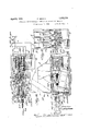
- Figure l is a fragmentary front elevation of an apparatus embodying my invention and mechanically controlled by key releasing means.
- Fig. 2 is a section on line 2--2 of Fig. l showing the article and holder in side elevation.
- Fig. 3 is a section on line 3-3 of Fig. 1 with parts in unlocked position.
- Fig. 4 is a view of a key.
- Fig. 5 is a detail view of the relative disposition of the vertical and horizontal cooperating pins.
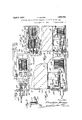
- Fig. 6 is a view similar to Fig. 3 of a modified arrangement in which the device'is elec- 1929. Serial No. 355,764.
- Fig. 7 is a ⁇ section substantially on line 7-7 of Fig. 6 and showing the wiring for the electric circuit.
- Fig. 8 shows an embodiment of my invention in which the solenoid circuit for releasing the locking pin is coin controlled, the coins closing the circuit.
- Fig. 9 is a section on line 9-9 of Fig. 8.
- Fig. l0 shows a preferred embodiment of my invention in which the solenoid is arranged so that it is operable by key, coin, or switchboard.
- Fig. ll is a fragmentary front view of the apparatus of Fig. l0.
- Fig. l2 is a section substantially on line 12-i2 of Fig. i0.
- the article 1 consisting of the sealed package containing a pair of stockings or the like is received in the holder 2 of which there' is one for each article, the holders being preferably arranged in series or banks as shown.
- the holder comprises anV L-shaped channel member removably attached to the frame or casing 3, the frame 3 having upwardly disposed projections or pins 4 adapted to engage eye members 5 on the holder to support the holder and its contents, with its lower edge in spaced apart relation to the floor 6 of the frame or casing 3.
- the lower forward end of the L-shaped holder 2 is providedwith a movable stop member 7, the stop member 7 being movable into and out of position to restrain and prevent removal of the article or package from the holder.
- the stop member consists of a plate 7 pivotally mounted to the holder adjacent its forward open end.
- the stop member plate consists of an upper stop or closure portion 7a and a lower portion 7?) depending below the pivot.
- a pin 11 is vertically movable in a guide bore or slot 11a provided in a bracket 12 depending ⁇ from the holder.
- the pin 11 is provided with an aperture 13 therein to be engaged by a lifting member or tool of any vsuitable form having a projection to fit the aperture 13. rfhe pin is thus movable to locking position behind said pivoted stop plate to retain the same in closed position ⁇ shown in Figs. 2 and 6.
- a horizontally movable pin 14 is disposed with relation to the vertically movable pin 11 to hold the pin 11 in uppermost position as shown in Figs. 5, 2, and 6.
- the horizontal pin 14 is spring pressed forwardly by spring 15 and is guided in guide bores 16 carriedby the bracket 12.
- the front 17 is provided with keyholes 18 and is preferably hinged to the casing and provided with a suitable lock 20, similarly to the hinged cover 9.
- the key 21V such as is shown in Fig. 4 and which may be designed with any suitable cross sectional shape, to it a corresponding keyhole 18, is provided with a cut out portion 22 for receiving the pin 11 as shown in Fig. 3, after the pin 14 has been pushed back by the key.
- a spring 23 is preferably provided and urges the stop member to open position.
- the purchaser makes the desired selection by inspection of the articles which are exposed to view and marked with all necessary information, sucli as size, shade, and material of the hosiery in the containers. After selection is made, the purchaser goes to the store operator, makes the selection known, and upon payment for the article secures the proper key or keys for the article or articles desired. The purchaser then secures the desired article by insertion of the key which releases the lock, and the article may then be withdrawn by the tab.
- the holder In refilling or restocking the dispenser apparatus, the holder is restocked with an article of the proper kind, the stop member is moved to closed position and at the same time, the vertical pin 11 is moved upwardly by a suitable lifting tool (not shown) in-- serted through the slots 43 into position, to clear the key and to provide a lock for the pivoted stop plate. This causes the horizontal pin 14 to move beneath the vertical pin. The key is then entirely removed and the device is ready for re-use by the next purchaser.
- Fig. 6 I show a solenoid 24 for effecting the withdrawal of the horizontal pin 14.
- the solenoid in Fig. 6 is controlled by an electric circuit 25 including source of power 26 such as battery or power line, and adapted to be closed by key 21a closing the space between terminals 27 and 28.
- source of power 26 such as battery or power line
- key 21a closing the space between terminals 27 and 28.
- terminals 2T and 28 are fastened to the iioor of the casing and are adapted to be sprung slightly apart to allow reception of the key 21a therebetween in firm contact.
- the circuit Upon insertion of the key 21a, the circuit is closed and the solenoid 24 is energized and acts to withdraw the horizontal pin 14 causing the device to operate above described with respect to Figs. 1, 2, and 3.
- the key may withdrawn by the customer and returned to the operator or the operator may procure the key from the unit when refilling.
- the solenoids 24 are arranged, one for each of the lock releasing pins, for each of the individual article holders, and the solenoids may be controlled through circuits in parallel with each other from -a common source of power.
- switches 29 and 30 which illustrate independent control by a switchboard controlled by the operator.
- the use of the switchboard 29 and 30, is independent of-the keys, and controls independent circuits 31 and 82 operated by the same power source 16.
- the key system or the switchboard system may be used as desired, the device as constructed being capable of use by either system according to the wish of the storekeeper or owner.
- Fig. 9 I have shown an embodiment of my invention in which the solenoids are controlled by circuit closing coinQ and in which the requisite number of coins of the proper denomination must be inserted.
- rEhe coin chute 33 is formed of a metal conductor portion 33a and an insulation portion 33?).
- the first coin inserted is .adapted to contact with contact terminal 34 and the last coin inserted is adapted to contact with the conductor portion 33a.
- the intermediate coins complete the circuit, through the coins, lterminal 34, solenoid 24, battery 26 and conductor portion 33a..
- the separate circuits are arranged in parallel as before and may be Icontrolled from the same power source 26.
- the coin chute 33 is pivotally mounted at 33u Cil and bears at its forward end upon the casing front at 330 so that it may be discharged, by unlocking the casing front, swinging the front down 'about its hinge and 1then tipping the chute forwardlyto discharge the coins.
- Figs. 10, 11, and 12 I show a preferred embodiment of my invention in which the owner storekeeper is ⁇ giventhe choice of the switchboard, key, or coin controlled electric system for operating the solenoids. Also in this embodiment is shown a preferred structure of stop member.
- the stop member 7 c in this embodiment consists of a plunger rod provided with a push button 7d, the rod 7c being spring pressed upwardly by spring and being held in upward position by horizontal pin 14a engaging notch V7e in the rear face of the rod 7 c. Vhen the pin 14a is withdrawn, the stop rod 7c must be pushed down before the article can be removed from the holder.
- the solenoid 24a one for each pin 14a, is operated by electric circuits including source of power 260: and controlled either by switchboard 29e, 30a, or by key 210 or by coins in chute 33a.
- the key 210 is provided with insulation 36 and with notch 37, the notch 37 being adapted to be engaged by spring pressed detent 38 to determine and hold the key in proper circuit closing position and to prevent removal of the key by the customer.
- the detent and notch arrangement serves to prevent removal of the key by the customer.
- the terminals 27 c and 280 are also of spring metal and adapted to be spread slightly apart by the key to ensure firm contact.
- the detent 38 is lifted by the operator by means of a releasing key 43 which is inserted in key hole 18h alongside the keyhole 18a. The key 210 may then be withdrawn, breaking the solenoid circuit.
- the coin controlled circuit is designated in 'l Fig. 12 by the letter A, the key circuit is designated by B and the switchboard circuit by the letter C and may be readily traced from Fig. 12.
- Fig. 11 shows the front of the casing with the slots 41 for the insertion of the coins and also shows the stop rods 7 c and key holes 18a.
- Figs. 6 and 7 may, if desired, be provided with the arrangement of Figs. 10, 11, and 12 to prevent removal of the key by the customer, and only by the operator.
- the sealed packages containing the articles such as hosiery are preferably each provided with windows 42 to permit inspection of the color and quality of the material. This can be seen on the end package of a series of holders and is, of course, seen upon removal from the holder, to check the label and permit final inspection.
- the invention is intended to greatly facilitate the dispensing of articles such as hosiery, by providing a means whereby a complete hosiery store may be operated by a minimum of attendants, and to eliminate the present great loss entailed by spoiling of the goods by repeated handling by purchasers.
- the device also serves to prevent handling and misplacement of the packages by purchasers, it not being intended as a theft proof arrangement at all, though it does serve that purpose to some extent, but is open to inspection and is readily accessible and is intended as a means providing for ready dispensing of articles after selection, and for compelling the selection to be made without handling of the articles.
- the solenoid controlled locking pin is an effective means of accomplishing the object of my invention
- the form of my invention embodying the mechanical key control shown in Figs. 1, 2, and 3 is a very prac- This key is sold or delivered to the customer after the selection is made by the customer.
- the customer on entering the "store app reaches the unit comprising a series or sets of article holders and inspects colors and quality properly marked or labeled with respect to the series or sets or units and on each sealed package of hose.
- the colors may be displayed upon a well illuminated board or at each package holder.
- Quality may be displayed by sample upon a display board arranged adjacent or on the units or series of holders, though the quality feature will be accepted from the words chiifonserviceheavy weight, also through dependence upon the responsible merchants and upon previous knowledge of quality.
- a high standard of quality with a lowest possible price is the ultimate purpose of this invention. After the customer determines the kind and price of stocking she desires, the merchant or operator is paid. A key, to fit the lock of the compartment or holder to release the package is given to the customer. The key after having been used to open the lock, cannot be withdrawn by the customer, due to the detent arrangement provided as shown in Figs. 1, 2, 3, 10, 11, and 12.
- the switchboard type of control for the solenoid enables the opening of the compartment or holder to allow the package to be removed, by means of an electric switch in the hands of the operator or cashier.
- the customer after having made a decision as to Vthe hose or article to be purchased, makes ⁇ feet condition and shape, and keeps the sizes under control.
- article dispensing apparatus having holders for the articles arranged side by side, said holders comprising L-shaped channel members open at the inner edge, the upper end being closed by a hinged door, the lower forward end being provided with a stop member movable to close and open said end to prevent or permit removal or insertion of the article in the holder, the article being of a shape to it in the channel of the L-shaped vholder and to be exposed therein forready removal from the holder.
- .said stop member comprises a vertically movable slide, a spring pressing said slide upwardly, said slide having a notch in its side, a pin horizontally movable to and from engagement With the notch in said slide to hold the same in elevated operative position or to release the same to permit its being moved downward, and means to operate said pin.
Landscapes
- Physics & Mathematics (AREA)
- General Physics & Mathematics (AREA)
- Control Of Vending Devices And Auxiliary Devices For Vending Devices (AREA)
Description
F. BROWN 1,852,733
APPARATUS FOR DISPENSING PACKAGES OF HOSIERY OF. THE LIK April 5, v19312.
5 sheets-sheer 1 Filed April 17, 1929 il ||Il lllll y/ I. ATTOJ F.. BROW N Apfil 5, 1932.
APPARATUS FOR DISPENSING PACKAGES OF HOSIERY OR THE LIKE Filed April 17. 1929 3 Sheets-Sheet 2 SNN M M w w u M NR W N .S1 f 3 www?. NNDNNGNEGN .NONQNNQQM N f\\\. n N. N L UQ. :ww URW w uw O. mi Hu l WNY www r I ...m O i m b :mw \I| ml m| n N n J M mikm ATTORNEYS fW April 5, 1932. F. BROWN 1,852,733
APPARATUS FOR DISPENSING PACKAGES OF HOSIERY OR THE LIKE Patented Apr. 5, 1932 UNETED srrss PATENT oli-Fics` FRANKLIN BROWN OF FRANKF'ORD, PHILA-DKEiPHIA, PENNSYLVANIA, ASSIGNOR, I-BY MESNE ASSIGNBIENTS, T0 HI/SELF AND GERALDINE F. BROWN, OF :PHILADEL- PHIA, PENNSYLVANIA .APPARATUS FOR DISPENSING PACKAGES OF HOSIERY OR THE LIKE Application filed April 17,
My present invention relates toimprovements in article dispensing apparatus.
An object of the invention is the provision of apparatus for permitting ready inspection of the articles by the purchaser in making selection, While preventing handling and removal of and misplacement and replacement by the purchaser in the wrong place, the article being promptly delivered to the purchaser after selection is made from the labeled articles. i
Another object is the provision of a novel form of individually releasable locking means for each article, such as a pair of hose or stockings entirely encased in a sealed package, the package being completely labeled with all desired information.
A further object is to provide such apparatus as will enable the ready dispensing of articles such as packages of hose, or the like, requiring the presence of but a single attendant in the whole store, which may contain any number of the individual releasable article holders or series thereof.
Other objects will appear hereinafter.
The invention consists in the features, combination, and arrangement of parts hereinafter described and particularly pointed out in the claims.
In the drawings:
Figure l is a fragmentary front elevation of an apparatus embodying my invention and mechanically controlled by key releasing means.
Fig. 2 is a section on line 2--2 of Fig. l showing the article and holder in side elevation.
Fig. 3 is a section on line 3-3 of Fig. 1 with parts in unlocked position.
Fig. 4 is a view of a key.
Fig. 5 is a detail view of the relative disposition of the vertical and horizontal cooperating pins.
Fig. 6 is a view similar to Fig. 3 of a modified arrangement in which the device'is elec- 1929. Serial No. 355,764.
trically controlled by a solenoid', the circuit of which is closed by the key. Y
Fig. 7 is a` section substantially on line 7-7 of Fig. 6 and showing the wiring for the electric circuit.
Fig. 8 shows an embodiment of my invention in which the solenoid circuit for releasing the locking pin is coin controlled, the coins closing the circuit.
Fig. 9 is a section on line 9-9 of Fig. 8.
Fig. l0 shows a preferred embodiment of my invention in which the solenoid is arranged so that it is operable by key, coin, or switchboard.
Fig. ll is a fragmentary front view of the apparatus of Fig. l0.
Fig. l2 is a section substantially on line 12-i2 of Fig. i0.
Referring tothe drawings, the article 1 consisting of the sealed package containing a pair of stockings or the like is received in the holder 2 of which there' is one for each article, the holders being preferably arranged in series or banks as shown. As best shown in Fig. 2, the holder comprises anV L-shaped channel member removably attached to the frame or casing 3, the frame 3 having upwardly disposed projections or pins 4 adapted to engage eye members 5 on the holder to support the holder and its contents, with its lower edge in spaced apart relation to the floor 6 of the frame or casing 3.
The lower forward end of the L-shaped holder 2 is providedwith a movable stop member 7, the stop member 7 being movable into and out of position to restrain and prevent removal of the article or package from the holder.
ln operation when the stop is withdrawn, the article must be removed by pulling forwardly upon the tab means 8 thereon, the upper ends of the holder being covered by a cover member 9 hinged to the casing and Asecurely locked in place by suitable locking means l0.
Below the holder in the space between it and the floor 6 of the casing 3 is arranged the locking means for the stop member 7.
In the embodiment shown in Figs. 2, 8, 6, and 8, the stop member consists of a plate 7 pivotally mounted to the holder adjacent its forward open end. The stop member plate consists of an upper stop or closure portion 7a and a lower portion 7?) depending below the pivot.
A pin 11 is vertically movable in a guide bore or slot 11a provided in a bracket 12 depending` from the holder. The pin 11 is provided with an aperture 13 therein to be engaged by a lifting member or tool of any vsuitable form having a projection to fit the aperture 13. rfhe pin is thus movable to locking position behind said pivoted stop plate to retain the same in closed position `shown in Figs. 2 and 6.
A horizontally movable pin 14 is disposed with relation to the vertically movable pin 11 to hold the pin 11 in uppermost position as shown in Figs. 5, 2, and 6.
The horizontal pin 14 is spring pressed forwardly by spring 15 and is guided in guide bores 16 carriedby the bracket 12.
The front 17 is provided with keyholes 18 and is preferably hinged to the casing and provided with a suitable lock 20, similarly to the hinged cover 9.
'With reference to Figs. 1, 2, 3, and 4, the key 21V such as is shown in Fig. 4 and which may be designed with any suitable cross sectional shape, to it a corresponding keyhole 18, is provided with a cut out portion 22 for receiving the pin 11 as shown in Fig. 3, after the pin 14 has been pushed back by the key.
Vhen the key and vertical pin are in the position shown in Fig. 3, the hinged stop member 7 is free to move to the open position shown in dotted lines. Removal of the article from the holder is then easily accomplished. A spring 23 is preferably provided and urges the stop member to open position.
In the use of this form of my invention, the purchaser makes the desired selection by inspection of the articles which are exposed to view and marked with all necessary information, sucli as size, shade, and material of the hosiery in the containers. After selection is made, the purchaser goes to the store operator, makes the selection known, and upon payment for the article secures the proper key or keys for the article or articles desired. The purchaser then secures the desired article by insertion of the key which releases the lock, and the article may then be withdrawn by the tab.
In refilling or restocking the dispenser apparatus, the holder is restocked with an article of the proper kind, the stop member is moved to closed position and at the same time, the vertical pin 11 is moved upwardly by a suitable lifting tool (not shown) in-- serted through the slots 43 into position, to clear the key and to provide a lock for the pivoted stop plate. This causes the horizontal pin 14 to move beneath the vertical pin. The key is then entirely removed and the device is ready for re-use by the next purchaser.
In Fig. 6, I show a solenoid 24 for effecting the withdrawal of the horizontal pin 14. The solenoid in Fig. 6 is controlled by an electric circuit 25 including source of power 26 such as battery or power line, and adapted to be closed by key 21a closing the space between terminals 27 and 28. rIhe terminals 2T and 28 are fastened to the iioor of the casing and are adapted to be sprung slightly apart to allow reception of the key 21a therebetween in firm contact.
Upon insertion of the key 21a, the circuit is closed and the solenoid 24 is energized and acts to withdraw the horizontal pin 14 causing the device to operate above described with respect to Figs. 1, 2, and 3. The key may withdrawn by the customer and returned to the operator or the operator may procure the key from the unit when refilling.
As shown in Figs. 7, 9, and 12, the solenoids 24 are arranged, one for each of the lock releasing pins, for each of the individual article holders, and the solenoids may be controlled through circuits in parallel with each other from -a common source of power.
Also shown in Fig. 7 are switches 29 and 30 which illustrate independent control by a switchboard controlled by the operator. The use of the switchboard 29 and 30, is independent of-the keys, and controls independent circuits 31 and 82 operated by the same power source 16. Thus with the arrangement shown in Fig. 7, the key system or the switchboard system may be used as desired, the device as constructed being capable of use by either system according to the wish of the storekeeper or owner.
In Fig. 9, I have shown an embodiment of my invention in which the solenoids are controlled by circuit closing coinQ and in which the requisite number of coins of the proper denomination must be inserted. rEhe coin chute 33 is formed of a metal conductor portion 33a and an insulation portion 33?). The first coin inserted is .adapted to contact with contact terminal 34 and the last coin inserted is adapted to contact with the conductor portion 33a. The intermediate coins complete the circuit, through the coins, lterminal 34, solenoid 24, battery 26 and conductor portion 33a.. The separate circuits are arranged in parallel as before and may be Icontrolled from the same power source 26. The coin chute 33 is pivotally mounted at 33u Cil and bears at its forward end upon the casing front at 330 so that it may be discharged, by unlocking the casing front, swinging the front down 'about its hinge and 1then tipping the chute forwardlyto discharge the coins.
In Figs. 10, 11, and 12, I show a preferred embodiment of my invention in which the owner storekeeper is` giventhe choice of the switchboard, key, or coin controlled electric system for operating the solenoids. Also in this embodiment is shown a preferred structure of stop member.
The stop member 7 c in this embodiment consists of a plunger rod provided with a push button 7d, the rod 7c being spring pressed upwardly by spring and being held in upward position by horizontal pin 14a engaging notch V7e in the rear face of the rod 7 c. Vhen the pin 14a is withdrawn, the stop rod 7c must be pushed down before the article can be removed from the holder.
The solenoid 24a, one for each pin 14a, is operated by electric circuits including source of power 260: and controlled either by switchboard 29e, 30a, or by key 210 or by coins in chute 33a.
The key 210 is provided with insulation 36 and with notch 37, the notch 37 being adapted to be engaged by spring pressed detent 38 to determine and hold the key in proper circuit closing position and to prevent removal of the key by the customer. The detent and notch arrangement serves to prevent removal of the key by the customer.
In this embodiment, the terminals 27 c and 280 are also of spring metal and adapted to be spread slightly apart by the key to ensure firm contact. In this embodiment, the detent 38 is lifted by the operator by means of a releasing key 43 which is inserted in key hole 18h alongside the keyhole 18a. The key 210 may then be withdrawn, breaking the solenoid circuit.
The coin controlled circuit is designated in 'l Fig. 12 by the letter A, the key circuit is designated by B and the switchboard circuit by the letter C and may be readily traced from Fig. 12.
Fig. 11 shows the front of the casing with the slots 41 for the insertion of the coins and also shows the stop rods 7 c and key holes 18a.
It will be understood that the device shown in Figs. 6 and 7 may, if desired, be provided with the arrangement of Figs. 10, 11, and 12 to prevent removal of the key by the customer, and only by the operator.
The sealed packages containing the articles such as hosiery are preferably each provided with windows 42 to permit inspection of the color and quality of the material. This can be seen on the end package of a series of holders and is, of course, seen upon removal from the holder, to check the label and permit final inspection.
I do not desire to limit myself to the exact ,tical arrangement.
construction shown, it being apparent that many modifications may be made within the scope of my invention as herein described and claimed. y
` The numerals 9, 10, 11, 12, 13, 14 on the stop members 7 in Fig. 1 are merely illustrative of any desired marking to designate and differentiate the article to be received in the holders.
The invention is intended to greatly facilitate the dispensing of articles such as hosiery, by providing a means whereby a complete hosiery store may be operated by a minimum of attendants, and to eliminate the present great loss entailed by spoiling of the goods by repeated handling by purchasers.
The device also serves to prevent handling and misplacement of the packages by purchasers, it not being intended as a theft proof arrangement at all, though it does serve that purpose to some extent, but is open to inspection and is readily accessible and is intended as a means providing for ready dispensing of articles after selection, and for compelling the selection to be made without handling of the articles.
While the solenoid controlled locking pin is an effective means of accomplishing the object of my invention, the form of my invention embodying the mechanical key control shown in Figs. 1, 2, and 3, is a very prac- This key is sold or delivered to the customer after the selection is made by the customer.
The customer on entering the "store appreaches the unit comprising a series or sets of article holders and inspects colors and quality properly marked or labeled with respect to the series or sets or units and on each sealed package of hose. The colors may be displayed upon a well illuminated board or at each package holder. Quality may be displayed by sample upon a display board arranged adjacent or on the units or series of holders, though the quality feature will be accepted from the words chiifonserviceheavy weight, also through dependence upon the responsible merchants and upon previous knowledge of quality.
A high standard of quality with a lowest possible price is the ultimate purpose of this invention. After the customer determines the kind and price of stocking she desires, the merchant or operator is paid. A key, to fit the lock of the compartment or holder to release the package is given to the customer. The key after having been used to open the lock, cannot be withdrawn by the customer, due to the detent arrangement provided as shown in Figs. 1, 2, 3, 10, 11, and 12.
The switchboard type of control for the solenoid enables the opening of the compartment or holder to allow the package to be removed, by means of an electric switch in the hands of the operator or cashier. The customer, after having made a decision as to Vthe hose or article to be purchased, makes `feet condition and shape, and keeps the sizes under control.
I claim:
l. In article dispensing apparatus having holders for the articles arranged side by side, said holders comprising L-shaped channel members open at the inner edge, the upper end being closed by a hinged door, the lower forward end being provided with a stop member movable to close and open said end to prevent or permit removal or insertion of the article in the holder, the article being of a shape to it in the channel of the L-shaped vholder and to be exposed therein forready removal from the holder.
, 2. Apparatus according to claim 1 in which .said stop member comprises a vertically movable slide, a spring pressing said slide upwardly, said slide having a notch in its side, a pin horizontally movable to and from engagement With the notch in said slide to hold the same in elevated operative position or to release the same to permit its being moved downward, and means to operate said pin.
3. In combination, with article dispensing apparatus-including holders for the articles arranged side by side, and a stop member on the holder to prevent removal of the article from the holder, of the type in which the stop member comprises a plate pivotally mounted on the holder and movable into elevated operative position and into depressed inoperative position, and releasable locking means for said movable stop member, said locking means according to the present invention comprising a vertically movable pin adapted when lifted to engage the lower end of said pivoted plate to sold it in elevated operative position, and a horizontally movable pin adapted when in advanced position to engage the vertically movable pin to hold it in lifted position, key means for each article and holder manually operable to push the horizontal pin from advanced position to withdraw unlocking position, and to permit dropping of said vertical pin and said pivoted plate, said horizontal pin being spring pressed to advanced position, means providling for lifting of said vertical pin to locking position and for withdrawal of said key, and
FRANKLIN BROWN.
Priority Applications (1)
| Application Number | Priority Date | Filing Date | Title |
|---|---|---|---|
| US355764A US1852733A (en) | 1929-04-17 | 1929-04-17 | Apparatus for dispensing packages of hosiery or the like |
Applications Claiming Priority (1)
| Application Number | Priority Date | Filing Date | Title |
|---|---|---|---|
| US355764A US1852733A (en) | 1929-04-17 | 1929-04-17 | Apparatus for dispensing packages of hosiery or the like |
Publications (1)
| Publication Number | Publication Date |
|---|---|
| US1852733A true US1852733A (en) | 1932-04-05 |
Family
ID=23398744
Family Applications (1)
| Application Number | Title | Priority Date | Filing Date |
|---|---|---|---|
| US355764A Expired - Lifetime US1852733A (en) | 1929-04-17 | 1929-04-17 | Apparatus for dispensing packages of hosiery or the like |
Country Status (1)
| Country | Link |
|---|---|
| US (1) | US1852733A (en) |
Cited By (6)
| Publication number | Priority date | Publication date | Assignee | Title |
|---|---|---|---|---|
| US3061143A (en) * | 1959-06-18 | 1962-10-30 | Universal Match Corp | Article vending machine |
| US3172713A (en) * | 1961-10-30 | 1965-03-09 | Nac De Inversiones S A Empresa | Vending machine apparatus |
| US20070102259A1 (en) * | 2003-12-26 | 2007-05-10 | Konami Digital Entertainment Co., Ltd. | Method of determining completion of coin insertion and coin recovering device for automatic vending machine |
| US20070175915A1 (en) * | 2003-12-26 | 2007-08-02 | Konami Digital Entertainment Co., Ltd. | Automatic vending machine |
| US20070193318A1 (en) * | 2006-01-27 | 2007-08-23 | Alex Churchill | Consumer product dispensing system |
| US20110000760A1 (en) * | 2009-07-01 | 2011-01-06 | Lacroix-Toyne Nancy | Vending apparatus and method |
-
1929
- 1929-04-17 US US355764A patent/US1852733A/en not_active Expired - Lifetime
Cited By (11)
| Publication number | Priority date | Publication date | Assignee | Title |
|---|---|---|---|---|
| US3061143A (en) * | 1959-06-18 | 1962-10-30 | Universal Match Corp | Article vending machine |
| US3172713A (en) * | 1961-10-30 | 1965-03-09 | Nac De Inversiones S A Empresa | Vending machine apparatus |
| US20070102259A1 (en) * | 2003-12-26 | 2007-05-10 | Konami Digital Entertainment Co., Ltd. | Method of determining completion of coin insertion and coin recovering device for automatic vending machine |
| US20070175915A1 (en) * | 2003-12-26 | 2007-08-02 | Konami Digital Entertainment Co., Ltd. | Automatic vending machine |
| EP1701314A4 (en) * | 2003-12-26 | 2010-01-20 | Konami Digital Entertainment | Automatic vending machine |
| EP1701311A4 (en) * | 2003-12-26 | 2010-01-20 | Konami Digital Entertainment | Method of determining completion of coin insertion and coin recovering device for automatic vending machine |
| US7793769B2 (en) | 2003-12-26 | 2010-09-14 | Konami Digital Entertainment Co., Ltd. | Automatic vending machine |
| US20070193318A1 (en) * | 2006-01-27 | 2007-08-23 | Alex Churchill | Consumer product dispensing system |
| WO2007089749A3 (en) * | 2006-01-27 | 2007-12-21 | Ferrellgas L P | Consumer product dispensing system |
| US20110000760A1 (en) * | 2009-07-01 | 2011-01-06 | Lacroix-Toyne Nancy | Vending apparatus and method |
| US9495823B2 (en) * | 2009-07-01 | 2016-11-15 | Bobrick Washroom Equipment, Inc. | Vending apparatus and method |
Similar Documents
| Publication | Publication Date | Title |
|---|---|---|
| US2832506A (en) | Dispensing machine | |
| US1010993A (en) | Coin-receiver and money-changer. | |
| US2304533A (en) | Cigarette dispenser | |
| US2435526A (en) | Multiple compartment vending machine | |
| US1852733A (en) | Apparatus for dispensing packages of hosiery or the like | |
| US3800932A (en) | Coin operated card vending machine | |
| US3709404A (en) | Vending machine | |
| US1644371A (en) | goldman | |
| US3397764A (en) | Article delivery system | |
| US1939127A (en) | Vending machine | |
| US2094433A (en) | Vending machine | |
| US1495217A (en) | Vending machine | |
| US1839480A (en) | Vending machine | |
| US3190493A (en) | Mechanism for vending cylindrical products | |
| US1936515A (en) | Vending machine | |
| US2180326A (en) | Vending machine | |
| US2916186A (en) | Dispensing machine for heavy articles | |
| US3137533A (en) | Traveling independent carrier merchandising machine | |
| US1656752A (en) | Coin-freed vending apparatus | |
| US620527A (en) | Co in-co nt rolled vending-machine | |
| US1049414A (en) | Coin-operated vending-machine. | |
| US963245A (en) | Machine for handling articles. | |
| US1905169A (en) | Vending machine attachment | |
| US1869070A (en) | Vending machine | |
| US1634581A (en) | Vending machine |