US1852726A - Cutting machine for paper and the like - Google Patents
Cutting machine for paper and the like Download PDFInfo
- Publication number
- US1852726A US1852726A US75846A US7584625A US1852726A US 1852726 A US1852726 A US 1852726A US 75846 A US75846 A US 75846A US 7584625 A US7584625 A US 7584625A US 1852726 A US1852726 A US 1852726A
- Authority
- US
- United States
- Prior art keywords
- wheel
- coupling
- saddle
- cutting
- lever
- Prior art date
- Legal status (The legal status is an assumption and is not a legal conclusion. Google has not performed a legal analysis and makes no representation as to the accuracy of the status listed.)
- Expired - Lifetime
Links
- 238000005520 cutting process Methods 0.000 title description 90
- 230000008878 coupling Effects 0.000 description 59
- 238000010168 coupling process Methods 0.000 description 59
- 238000005859 coupling reaction Methods 0.000 description 59
- 239000000463 material Substances 0.000 description 39
- 239000000123 paper Substances 0.000 description 10
- 239000011111 cardboard Substances 0.000 description 4
- 239000011435 rock Substances 0.000 description 3
- 230000001105 regulatory effect Effects 0.000 description 2
- 101100042271 Mus musculus Sema3b gene Proteins 0.000 description 1
- 102100034742 Rotatin Human genes 0.000 description 1
- 101710200213 Rotatin Proteins 0.000 description 1
- 230000005540 biological transmission Effects 0.000 description 1
- 230000006835 compression Effects 0.000 description 1
- 238000007906 compression Methods 0.000 description 1
- 238000012937 correction Methods 0.000 description 1
- 238000006073 displacement reaction Methods 0.000 description 1
- 230000000694 effects Effects 0.000 description 1
- 238000007689 inspection Methods 0.000 description 1
- 238000012986 modification Methods 0.000 description 1
- 230000004048 modification Effects 0.000 description 1
- 230000010355 oscillation Effects 0.000 description 1
- 230000000284 resting effect Effects 0.000 description 1
Images


Classifications
-
- B—PERFORMING OPERATIONS; TRANSPORTING
- B26—HAND CUTTING TOOLS; CUTTING; SEVERING
- B26D—CUTTING; DETAILS COMMON TO MACHINES FOR PERFORATING, PUNCHING, CUTTING-OUT, STAMPING-OUT OR SEVERING
- B26D1/00—Cutting through work characterised by the nature or movement of the cutting member or particular materials not otherwise provided for; Apparatus or machines therefor; Cutting members therefor
- B26D1/01—Cutting through work characterised by the nature or movement of the cutting member or particular materials not otherwise provided for; Apparatus or machines therefor; Cutting members therefor involving a cutting member which does not travel with the work
- B26D1/04—Cutting through work characterised by the nature or movement of the cutting member or particular materials not otherwise provided for; Apparatus or machines therefor; Cutting members therefor involving a cutting member which does not travel with the work having a linearly-movable cutting member
- B26D1/06—Cutting through work characterised by the nature or movement of the cutting member or particular materials not otherwise provided for; Apparatus or machines therefor; Cutting members therefor involving a cutting member which does not travel with the work having a linearly-movable cutting member wherein the cutting member reciprocates
- B26D1/08—Cutting through work characterised by the nature or movement of the cutting member or particular materials not otherwise provided for; Apparatus or machines therefor; Cutting members therefor involving a cutting member which does not travel with the work having a linearly-movable cutting member wherein the cutting member reciprocates of the guillotine type
-
- B—PERFORMING OPERATIONS; TRANSPORTING
- B26—HAND CUTTING TOOLS; CUTTING; SEVERING
- B26D—CUTTING; DETAILS COMMON TO MACHINES FOR PERFORATING, PUNCHING, CUTTING-OUT, STAMPING-OUT OR SEVERING
- B26D7/00—Details of apparatus for cutting, cutting-out, stamping-out, punching, perforating, or severing by means other than cutting
- B26D7/06—Arrangements for feeding or delivering work of other than sheet, web, or filamentary form
-
- Y—GENERAL TAGGING OF NEW TECHNOLOGICAL DEVELOPMENTS; GENERAL TAGGING OF CROSS-SECTIONAL TECHNOLOGIES SPANNING OVER SEVERAL SECTIONS OF THE IPC; TECHNICAL SUBJECTS COVERED BY FORMER USPC CROSS-REFERENCE ART COLLECTIONS [XRACs] AND DIGESTS
- Y10—TECHNICAL SUBJECTS COVERED BY FORMER USPC
- Y10T—TECHNICAL SUBJECTS COVERED BY FORMER US CLASSIFICATION
- Y10T83/00—Cutting
- Y10T83/444—Tool engages work during dwell of intermittent workfeed
- Y10T83/4443—Unicyclic
- Y10T83/4445—Convertible to and from unicyclic
-
- Y—GENERAL TAGGING OF NEW TECHNOLOGICAL DEVELOPMENTS; GENERAL TAGGING OF CROSS-SECTIONAL TECHNOLOGIES SPANNING OVER SEVERAL SECTIONS OF THE IPC; TECHNICAL SUBJECTS COVERED BY FORMER USPC CROSS-REFERENCE ART COLLECTIONS [XRACs] AND DIGESTS
- Y10—TECHNICAL SUBJECTS COVERED BY FORMER USPC
- Y10T—TECHNICAL SUBJECTS COVERED BY FORMER US CLASSIFICATION
- Y10T83/00—Cutting
- Y10T83/444—Tool engages work during dwell of intermittent workfeed
- Y10T83/4501—Work feed means controlled by means mounted on tool or tool support
- Y10T83/4513—Work feed means halted by means on tool or tool support
-
- Y—GENERAL TAGGING OF NEW TECHNOLOGICAL DEVELOPMENTS; GENERAL TAGGING OF CROSS-SECTIONAL TECHNOLOGIES SPANNING OVER SEVERAL SECTIONS OF THE IPC; TECHNICAL SUBJECTS COVERED BY FORMER USPC CROSS-REFERENCE ART COLLECTIONS [XRACs] AND DIGESTS
- Y10—TECHNICAL SUBJECTS COVERED BY FORMER USPC
- Y10T—TECHNICAL SUBJECTS COVERED BY FORMER US CLASSIFICATION
- Y10T83/00—Cutting
- Y10T83/444—Tool engages work during dwell of intermittent workfeed
- Y10T83/4539—Means to change tool position, or length or datum position of work- or tool-feed increment
- Y10T83/4541—With means to vary magnitude of work-feed increment
- Y10T83/4549—By change in length of one member of feed-driving linkage
-
- Y—GENERAL TAGGING OF NEW TECHNOLOGICAL DEVELOPMENTS; GENERAL TAGGING OF CROSS-SECTIONAL TECHNOLOGIES SPANNING OVER SEVERAL SECTIONS OF THE IPC; TECHNICAL SUBJECTS COVERED BY FORMER USPC CROSS-REFERENCE ART COLLECTIONS [XRACs] AND DIGESTS
- Y10—TECHNICAL SUBJECTS COVERED BY FORMER USPC
- Y10T—TECHNICAL SUBJECTS COVERED BY FORMER US CLASSIFICATION
- Y10T83/00—Cutting
- Y10T83/444—Tool engages work during dwell of intermittent workfeed
- Y10T83/4564—With means to produce plurality of work-feed increments per tool cycle
- Y10T83/4567—Including supplemental work-feed means
- Y10T83/4569—Manual
-
- Y—GENERAL TAGGING OF NEW TECHNOLOGICAL DEVELOPMENTS; GENERAL TAGGING OF CROSS-SECTIONAL TECHNOLOGIES SPANNING OVER SEVERAL SECTIONS OF THE IPC; TECHNICAL SUBJECTS COVERED BY FORMER USPC CROSS-REFERENCE ART COLLECTIONS [XRACs] AND DIGESTS
- Y10—TECHNICAL SUBJECTS COVERED BY FORMER USPC
- Y10T—TECHNICAL SUBJECTS COVERED BY FORMER US CLASSIFICATION
- Y10T83/00—Cutting
- Y10T83/444—Tool engages work during dwell of intermittent workfeed
- Y10T83/4647—One-revolution clutch in tool drive
Definitions
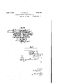
- Fig. 1 is a plan view of the improved machine
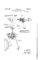
- Fig. 1a is an enlarged elevational detail partly in section of the reversing gear and conical coupling, the view being taken on line C-D of Fig. 1b,
- Fig. 1b is a top plan detail of the reversing gear and its associated parts, the reversing gear per se being shown in horizontal section on the line A-B of Fig. 1a.
- Fig. 1c is a diagrammatic view of the arrangement of the Gear wheels of the reversing gear taken on the line G-H of Fig. 1b,
- Fig. 1d is a diagrammatic view showing the other wheels of the reversing gear in engagement with each other
- Fig. 2 is an elevational view of the complete machine
- Fig. 2a is an enlarged vertical sectional view through the saddle wheel, coupling and adjacent parts
- Fig. 3 is an enlarged elevational detail for the setting lever for the saddle with adjoining parts.
- a motor engine 1 or the like may be provided for the actuation of the different moving parts of the machine.
- the fly Wheel 2 which is operated by the motor 1 and is preferably' provided with the usual friction coupling or the like is connected to the pinion or gear wheel 3 engaging with the gear wheel 4 from which by way of the gear wheels 5, 6, shaft 10, V clutch coupling 9 and worm gear 7, 8, and
- crank pin 13 provided on the crank 12 is adapted to engage from belovvi with a longitudinal slot of the rocking arm 14 which oscillates on the stud 15 provided on the supporting frame 16.
- the rotation of the crank arm 12 causes the rocking arm 14 to be rocked, and its oscillating movement is transmitted by means of the rod 17 to the disc 18 (Fig. 2).
- -. cone 24 are loosely mounted androtatable on a stud or shaft 86 which is secured in position bythe table 34 and the .support 87. ⁇
- the shaft 86 is longitudinally bored for thereception of the adjusting pin 29 and for securing the parts in the adjusted position an ⁇ adjusting nut 28 is provided at the end of the adjusting pin 29, the said nut 28'resting against the shaft 86 and being preferably connected thereto by means of the setting pin 28a which engages with an annular groove of the shaft or stud 86 andwith a suitable opening of the nut 28.
- the disc In order to vvmake sure that the rotation of the freely rotating disc 22 will take place in one direction only, the disc, besides relying upon the operation of the clutch rollers 21, may .be provided with a braking dis'c or ring 87 which is rigidly connected thereto.
- the braking ring 87 is adapted for engagement with the braking member 88 which is connected to the table 34 by means of.the screwbolt 89 and may be regulated and adjusted by means of the set screw 90, as clearly shown in Fig. lof the drawings.
- the friction cone 24 may be raised and lowered by means of the hand lever 25 with lever arm 25a, connecting rod 26, lever 27 and thel adj listing nut 28 with screws 28a and setting bolt 29 above referred to.
- the friction cone will become engaged and respectively disengaged with the quickly rotating wheel 30 intended for the operation of the saddle 33, the lowering of the friction cone in the exemplification shown in the drawings causing it to become engaged with the wheel 30, while by the raising of the friction cone 24 it is disconnected therefrom.
- the gear wheel or worm wheel 77 may be engaged with the gear vwheel 79 secured to the saddle wheel 30, as more particularly hereinafter described.
- the saddle wheel 30 will thereby vbe operated by the gear wheel or worm wheel 77.
- wire rope 31 which is passed over the guide rollers 31a and is tightened by the tensioning screws 32 the rotation of the saddle wheel 30 is transmitted to the saddle 33 carrying the screws 32 so that the saddle 33 may be reciprocated upon the table 34.
- the said stopping member 53 of the saddle 33 isforced simultaneously against the stopping screw 58 on the two-armed lever 59 adapted to rock on the stationary pivoting stud 60 and operatively connected to the bar 61 which is thereby withdrawn.
- the arresting lever 62 with the roller 69 is raised and the compression spring 63 becomes operative to Withdraw the shipping or engagement rod 64 which has been arrested by engagement with a recess or a stud of the arresting lever 62.
- the spring 63 acting upon the rod 64 rocks the coupling lever 65 on its stationary pivoting stud 66 and causes the friction coupling of the fly wheel 2 to be disengaged, so that the knife and the press beam, not shown in the drawings, are arrested in their uppermost position, While the Wheels 3, 4, 5, 6, the shaft 10 and the clutch member 9 continue their 'rotation with the fly Wheel 2 and without the worm wheel 7.
- the auxiliary tensional spring 67 returns the two-armed lever 59 and the auxiliary tensional spring 68 returns the two-armed lever 62 to their normal positions.
- the hand wheel 81 is to be emj nloyed for the operation of the Worm wheel 77 and of the saddle wheel 30 by hand, when the friction cone 24 is disengaged, While the arrangement of the lever arm 25a may be such that the driving of the saddle wheel 30 may be alternatingly produced either by the rocking member 14 or by the Worm Wheel 77 or the intermittent movement of the saddle wheel 30 produced by the rocking member 14 and the engagement of the friction cone 24 may be changed into a continuous movement by engagement with the Worm Wheel 77 with a corresponding adjustment of the hand lever 25.
- the driving of the Worm wheel 77 in both directions, so as to produce a continuous rapid movement of the gear Wheel 79 and of the saddle Wheel 30 in both directions, is effected from the sprocket wheel 71 which may be operated from the flywheel 2 by the gear wheels 3, 4.
- the shaft 74 is operated b v the chain drive 72 and sprocket Wheel 73.
- the reversing gear 75 is arranged which is connected to the shaft of the worm wheel 77 by a ball joint or the like 76, so that by the operation of the hand wheel 81 or of the lever arm 25a, as above described, the chain drive with the reversing gear may be operatively engaged and disengaged with the gear wheel 79.
- the reversing gear 75 includes five gear wheels 75a, 751;, 7 5c and 7 5c.
- the wheels 7 5c, 7 5c and 75d are mounted on the shaft 76 and rigidly connected to each other while the wheels 75a and 75?) are loosely mounted on the shaft 74.
- the conical coupling 75e is keyed to the shaft 74 and is adapted to be engaged with elther of the wheels 75a or 75?) to control the direction of rotation of the complete reversing gear.
- a hand lever 78 which is operably mounted on the casing of the reversing gear and operably associated with the conical coupling 75e through the instrumentality of a spring controlled pivot 7 8 the entire reversing gear 75 may be so adjusted that it will either produce right or left hand rotation of the worm wheel 77.
- the wheel 7 5d directly drives the Wheel 7 50 whereby a left hand rotation of the worm 77 is produced while in the other position of the friction cone 7 5e the wheel 75a drives the wheel 7 5c over the intermediate wheel 7 5cl. A right hand rotation of the worm 77 is thereby produced.
- the roller 39 which is operatively connected to the lever 51 and which is itself operated upon by the cam 38 on the knife shaft is moved by manipulating the handle indicated in the drawings in the direction of the arrow, thereby causing the feeding movement to be effected by the operation of the clutch 9.
- the engagement and disengagement of the driving means for the knife and of the press beam by hand may be effected by operating the hand lever 82 by means of which, when the lever 82 is set or engagement, the tension rod 64 is moved forward, so that the arresting lever 62 may Abecome engaged therewith and the friction coupling of the fly wheel becomes operated.
- the friction coupling is disengaged, the rod 61 is forced back by the hand lever 82, the arresting lever 62 is raised out of engagement and the spring 63 on the rod 64 becomes active and causes the disengagement of the friction coupling of the flywheel 2 by means of the lever 65.
- the saddle With the clutch member 9 disengaged and with the friction cone 24 in the inoperative position the saddle may be moved at a uniform rate in both directions by means of the machine bv merely operating the reversing gear 75 and swinging the worm wheel 77 into engagement with the gear wheel 30, the hand lever being then in the position I.
- This movement of the saddle is particularly important when the staple is put in position or inverted or otherwise handled.
- a hand wheel 80 is secured to the saddle wheel (Fig. 2) and the adjustment of the saddle by hand may be effected by operating the worm wheel 7 by means of the hand wheel 81 and swinging it into engagement with the gear wheel 79.
- the position of the which may have been caused by'irregsaddle 33 is indicated on the saddle wheel 30 by a graduation cooperating with an index finger 85 on the table 34 or the indicating members may be reversely arranged.
- both the staple feed as well as the cutting means may be operated both independently of as well as in combination with each other and thatthe feeding movement takes place during the complete or approximate stopping of the operation of the cutting means, all the manipulations being eifected either by machinery or by manual operation or by a combination thereof.
- the invention is, moreover, evidently applicable to the cutting of other sheet material and of piles and staples thereof besides paper, card board and the like.
- a support in combination, a support, a reciprocable feeding member on the support for the material, coupling means on said support and operably connected with the feeding member, a prime motor, an adjustable rocking member operatively connected to the prime motor and to said cou pling means, additional operating means for said feeding member, engageable and disenga eable therewith independently of said roc ing member, and cutting means for the material.
- a support in combination, a support, a reciprocable saddle on the support for the material, coupling means on said support and operably connected to the saddle, a prime motor, an adjustable rocking member o eratively connected to the prime motor an to said coupling means, a clutch intermediate the rime motor and the rocking member, cutting means for the material, operating means for said cutting means engageable with the prime motor, and means A on the operating means for the cutting means operatively engageable with the clutch and adapted to move the same into operative position substantially during the inoperative position of the cutting means.
- a support in combination, a support, a reciprocable saddle on the support for the material, coupling means on said support and operably connected to the saddle, a prime motor, an adjustable rocking member operatively connected to the prime motor and to said coupling means, additional operating and feeding means operatively connected to the primemotor and manually engageable and disengageable with the saddle, a clutch intermediate the prime motor and the rocking member, cutting 'means for the material, operating means for said cutting means engageable with the prime motor and adapted to discontinuously operate said cutting means, and means engageable with the cutting means and with the clutch and said cutting means, means engageable withV the cutting means and with the clutch and adapted to move the clutch into operative position substantially during the inoperative position of the cutting means, coupling'and uncoupling means intermediate the prime motor and cutting means and means operatively engageable with the cutting means and adapted to control and operate said coupling and uncoupling means.
- a support in combination, a support, a saddle for the material reciprocable on the support, a prime motor, driving and feeding means engageable with the saddle and adapted to reciprocate the same and operatively connected to the prime motor, a clutch member on said driving and feeding means, cutting means for the material and operating means for the cutting means engageable with the prime motor and adapted to discontinuously operate said cutting means, operatin means for the clutch engageable with t e cutting means and additional clutch-operating means engageable with the saddle, coupling and uncou ling means intermedia@ the prime motor an cutting means and means operatively engageable with the cutting means and adapted to control and operate said coupling and uncoupling means.
- a support for feeding the material reciprocable on the support, a prime motor, drivin means engageable with the saddle and a apted to reciprocate the .same and operatively ,connected to the prime motor, a clutch member on said driving means, operating means for the clutch member, cutting means for the material engageable wlth the prime motor and adapted to ldiseontinuously operate said cutting means, couplmgand uncoupling means intermediate the prime motor and cutting means operatively engageable with the cutting means and operating means for the coupling and uncoupling means operatively engageable with the saddle in certain positions thereof.
- a support in combination, a support, a feeding member for the material reciprocable on the support, a prime motor, a rocking member operatively connected to the prime motor adjustable link connection between the rocking member and the feeding member, means on the support for converting the rocking movement into reciprocating movement of the feeding member, additional manually operable moving means for the feedingmemberand discontinuously operated cutting means for the material.
- a support in combination, a support, a reciprocable feeder on the support for the material', a prime motor, a rocking member operatively connected to the prime motor, a rotating member and adjustable link connection between said member and the rocking member, coupling means between the rotating member and the feeder, means for adjusting and regulating the said coupling means, a clutch intermediate the rocking member and the prime motor, operating means for said clutch and cutting means for the material.
- a cutting machine in combination, a support, a reciprocable feeder on the support for the material, a prime motor, a rocking .member operativelyconnected to the prime motor, a driving wheel on the support and operatively connected to the feeder, a rotating member and adjustable link connection thereof with the rocking member, coupling means between the rotating member and the driving wheel for turning the wheel in one direction only, a clutch intermediate the rocking member and the prime motor, operating means for said clutch and cutting means for the material.
- a support in combination, a support, a reciprocable feeder on the support for the material, a prime motor, a rocking member operatively connected to the prime motor, a. driving wheel operatively connected to the feeder and adapted for manual operation, a rotating member and link connection thereof with the rocking member, coupling means between the rotating member and the .driving wheel, a reversing gear operatively connected to the prime motor, means to change the direction of rotation ofsaid gear and rockable driving means connected to said gear and engageable with the driving wheel and cutting means for the material.
- a cutting machine in combination, a sup ort, a reciprocable feeder on the support or the material, a prime motor, a rocking member operatively connected to the prime motor, a driving wheel 0 eratively connected to the feeder and ada te for manual operation, a rotating mem er' and link connection thereof with the rocking member, releasable coupling means between the rotating member and the driving wheel, braking means operatively associated with the coupling means and with t e rotating member and adapted to allow ro ation of the latter in one direction only, a reversing gear operatively connected to the prime motor, means to change the direction of rotation of said gear when the coupling means is released, rockable driving means connected to said gear and engageable with the rotatin member, an operating member connectedg to the coupling means and adapted to rock the driving means into and out of engaging position, and cutting means for the mater1al.
- a support in combination, a support, a mova le feeder onthesupport for the material, a prime motor and coupling means between t e motor and the movable feeder, cutting means for the material and operating means for the cutting means connected to the prime motor and adapted to discontinuously operate the cutting means, a coupling member intermediate the motor and the cutting means, spring-actuated lever connection between the cutting means and said coupling member and operating means for the spring-actuated lever connection.
- a support in combination, a support, a movable feeder on the support for the material, a prime motor and coupling and uncoupling means between the motor and the movable feeder ⁇ cutting means for the material and operating means for the cutting means connected to the prime motor and adapted to discontinuously operate the cutting means, a coupling member intermediate the motor and the cutting means, spring-actuated lever connection between the cutting means and said coupling member, a spring actuated lever engageable wih said lever connection and operatively connected to the coupling and uncoupling means for the feeder.
- a support, a movable -feeder on the support for the material, a prime motor, moving means for the feeder operated by themotor, a springactuated clutch intermediate the moving means and the motor cutting means for the material, two differently-sized coaxially disposed cams, link-members operatively engageable with the clutch, and operatively engageable with either of the cams.
- a support in combination, a support, a movable feeder on the support for the material tobe treated, a prime motor, moving means for the feeder, operatively connected to the motor, a spring-actuated clutch intermediate the moving means and the motor, cutting means for the material operated bythe motor, two differently-sized coaxially disposed cams, link-members operatively engageable with the clutch and operatively engageable with either of the cams, and additionalmanually operated actuating means on said link-members.
- a support In a paper cutting machine in combination, a support, a movable feeder on the support for the material, a prime motor, cutting means for the material operatively connected to the prime motor, coupling and unadapted to secure the same in the coupling position.
- a saddle drive in cutting machines for paper, cardboard and the like including in combination withV a saddle operating wheel, a conical toothed gear reversing drive, a conical coupling, and a hand lever for the purpose of obtaining a slow or intermittent feed of the saddle operating wheel and a consequent accurate adjustment thereof.
- a support In a cutting machine in combination, a support, a movable feeder on the support for the material, a prime motor, an operative con'- nection between the feeder and the motor, and
- a support in combination, a support, a movable feeder on the support for the material, a prime motor, cutting means for the material operatively coni nected to the prime motor, coupling and uncoupling means intermediate the motor and the cutting means, spring-actuated engaging and disengaging means for the coupling and uncoupling means, and a spring-induenced clutch adapted for engagement with the engaging and disengaging means and
Landscapes
- Life Sciences & Earth Sciences (AREA)
- Forests & Forestry (AREA)
- Engineering & Computer Science (AREA)
- Mechanical Engineering (AREA)
- Crushing And Pulverization Processes (AREA)
Description
April 5, 1932 K. STEGMANN CUTTING MACHINE FOR PAPER AND THE LIKE Filed Dec. 16, 1925 4 Sheets-Sheet 1 April 5, 193,2'.` K. STEGMANN CUTTING MACHINE FOR PAPER AND THE LIKEv Filed Dec. 16, 1925 4 Sheets-Sheet 2 April 55 1932. K, STEGMANN 1,852,726
CUTTING MACHINE FOR PAPER AND THE LIKE Filed Dec. 1e, '1925 4 sheetssheet 5 si i; a@ \I oa il :a O
I n ven for: l( Segmann April 5, 1932. K. sTEGMANN CUTTING MACHINE FOR PAPER AND THE LIKE Filed Dec. 16 1925 4 Sheets-Sheet 4 ofi/:e wheels 1a o Hg. la".
amffmafmo/uflan'qff/,e vm/5 in Meine 5"/7'.
Inventor: K/Sema'nn Jil-H.
Patented Apr. 5, 1932 UNITED STATES PATENT OFFICE KARL STEGMLANN, F BA'UTZEN, GERMANY ASSIGNOR TO JOHNE-WERK GRAFISCHE MASCHINEN-AKTIENGESELLSCHAFT, 0F BAUTZEN, GERMANY` CUTTING MACHINE FOR PAPER AND THE I-,IKE
Application ined December 1s, 1925. serial No. 75,846.
cutting machines and the like for the delivery or throwing oif and the determining of the cutting position of single or superimposed sheets of paper, card-board or the like, and it is intended to make provision whereby 1o all the various movementsand .adjustments of the saddle and the operatingvpyarts thereof may both be performed automatically as well as partly automatically and partly manually,
or entirely by manual operationf-in the disl cretion of the operator and in accordance with the requirements of the material and of the Working conditions.l In view thereof it is a further object of. this invention toconsiderably increase'the efficiency of machines of this kind, both as regards the output and the number of cuts to be performed in a minute and the exactness of operation and in particular of the cut and to further increase. the adaptability and the ease of manipulation of such machines and the yield thereof,
so as to amount to a multiple of the output produced with machines of the previous art not provided with similar arrangements. In connection therewith it is a further object of the invention to facilitate the manipulation of such machines for ordinary single cuts with automatic arresting of the knife in its highest position.
These and other objects of the invention will appear from an inspection of the drawings and from the specification illustrating by Way of example an embodiment of the principles of the invention, in which Fig. 1 is a plan view of the improved machine,
Fig. 1a is an enlarged elevational detail partly in section of the reversing gear and conical coupling, the view being taken on line C-D of Fig. 1b,
Fig. 1b is a top plan detail of the reversing gear and its associated parts, the reversing gear per se being shown in horizontal section on the line A-B of Fig. 1a.
Fig. 1c is a diagrammatic view of the arrangement of the Gear wheels of the reversing gear taken on the line G-H of Fig. 1b,
Fig. 1d is a diagrammatic view showing the other wheels of the reversing gear in engagement with each other,
Fig. 2 is an elevational view of the complete machine,
Fig. 2a is an enlarged vertical sectional view through the saddle wheel, coupling and adjacent parts,
Fig. 3 is an enlarged elevational detail for the setting lever for the saddle with adjoining parts.
Similar characters of reference are employed in all of the above described views to indicate corresponding parts.
The invention will be described with reference to the drawings, and with reference to its operation in connection with the manipulation and cutting of a staple of sheet material 35 which is supported on the table 34 and is fed by the feeder or saddle 33 reciprocably mounted on the table 34. A motor engine 1 or the like may be provided for the actuation of the different moving parts of the machine. The fly Wheel 2 which is operated by the motor 1 and is preferably' provided with the usual friction coupling or the like is connected to the pinion or gear wheel 3 engaging with the gear wheel 4 from which by way of the gear wheels 5, 6, shaft 10, V clutch coupling 9 and worm gear 7, 8, and
the shaft 11 of the worm Wheel 8 the feeding crank 12 which is secured to the shaft 11 may be operated. The crank pin 13 provided on the crank 12 is adapted to engage from belovvi with a longitudinal slot of the rocking arm 14 which oscillates on the stud 15 provided on the supporting frame 16. The rotation of the crank arm 12 causes the rocking arm 14 to be rocked, and its oscillating movement is transmitted by means of the rod 17 to the disc 18 (Fig. 2). By means of the hand Wheel 19 and the screw-threaded spindle 20 which are displaceably mounted on the rocking arm 14 and are connected to the pitman rod 17 the point of operative engagement of the rod 17 with the rocking arm 14 may be changed, so that the amplitude of oscillation of the rod 17 may be varied from a lar e amplitude down to zero. The extreme ositionsof the rocking arm 14 are indicated 1n the drawings partly by dotted lines. The
-. cone 24 are loosely mounted androtatable on a stud or shaft 86 which is secured in position bythe table 34 and the .support 87.\ The shaft 86 is longitudinally bored for thereception of the adjusting pin 29 and for securing the parts in the adjusted position an` adjusting nut 28 is provided at the end of the adjusting pin 29, the said nut 28'resting against the shaft 86 and being preferably connected thereto by means of the setting pin 28a which engages with an annular groove of the shaft or stud 86 andwith a suitable opening of the nut 28.
In order to vvmake sure that the rotation of the freely rotating disc 22 will take place in one direction only, the disc, besides relying upon the operation of the clutch rollers 21, may .be provided with a braking dis'c or ring 87 which is rigidly connected thereto. The braking ring 87 is adapted for engagement with the braking member 88 which is connected to the table 34 by means of.the screwbolt 89 and may be regulated and adjusted by means of the set screw 90, as clearly shown in Fig. lof the drawings.
The friction cone 24 may be raised and lowered by means of the hand lever 25 with lever arm 25a, connecting rod 26, lever 27 and thel adj listing nut 28 with screws 28a and setting bolt 29 above referred to. By this means the friction cone will become engaged and respectively disengaged with the quickly rotating wheel 30 intended for the operation of the saddle 33, the lowering of the friction cone in the exemplification shown in the drawings causing it to become engaged with the wheel 30, while by the raising of the friction cone 24 it is disconnected therefrom. By the rotation of the hand lever 25, so as to cause it to assume, for instance, the position indicated at I in Fig. 3 of the drawings the gear wheel or worm wheel 77 may be engaged with the gear vwheel 79 secured to the saddle wheel 30, as more particularly hereinafter described. The saddle wheel 30 will thereby vbe operated by the gear wheel or worm wheel 77. By means of wire rope 31 which is passed over the guide rollers 31a and is tightened by the tensioning screws 32 the rotation of the saddle wheel 30 is transmitted to the saddle 33 carrying the screws 32 so that the saddle 33 may be reciprocated upon the table 34.
Inasmuch as the feeding of the sheets should only take place, while the knives and the press-beam which are not shown in the drawing have assumed the position above the staple 35 with the'knife operating crank 36 and the pull-rod 37 for connection with the knife disposed so as to substantially correspond to the dead-center position of the crank arm, as shown in Fig. 2 of the drawings, the feeding movement will have to be commenced at this moment and it should be terminated as soon as the press-beam has become engaged again with the staple. This object maybe attained by correspondingly adjusting the 'rate of transmission of the driving wheels 3, 4, 5, 6 and by the fact that the operation and the arresting of the feeding gear will be respectively effected at the proper times. This adjustment and proport1oning of the feeding movement is effected in the following manner To the knife-operating crank 36 the cam 38 is rigidly connected which is in engagement with the roller 39 on the two-armed lever 51 which is thereby rocked on its pivot 40 and b means of the pitman-rod 41, and the lin 41a operates on the two-armed lever 42 which is rocked on its pivot 43,- causing the cam or roller 44 to be moved away from the path of the projection 46 of the worm Wheel 7 contrary to the action of the spring 45. The two-armed lever 42 with the cam roller 44 and the spring 45 are mounted on the forked lever 47 which latter is rotatably disposed on the pivoting' spring surrounding the shaft 1() tends to keep the coupling constantly in the engaging posltion. As soon, however, as the cam roller 44 is forced against the projection 46 of the wheel 7, the coupling is disengaged. In consequence of the lateral displacement of the roller 44 by the operation of the cam 38, the double lever 51, the link members 41, 41a and the two-armed lever 42, the roller 44 becomes disengaged from the projections 46 (as clearly shown in Fig. 1 of the drawings) and the spring 50 causes the coupling to be engaged and the feeding movement may then proceed as hereinbefore described. After a full rotation of the Wl1eel7 its projection 46 is again engaged with the roller 44 which `i has been forced back to its normal position by the spring 45, as soon as the cam 38 has become disengaged from the roller 39 and the two-armed lever 51 with the corresponding link members 41, 41a and the two-armed lever 42 have all been rocked back by the action of the auxiliary pulling spring 52. 1`he clutch 9 is now disengaged and the feeding movement has been terminated and the cutting of the staple or of the sheets may now be proceeded with. u
After` the saddle 33 has assumed its ex treme forward position, So that the entlre length of the staple of sheets has beenprogrcssively and intermittently fe d forward, as appears from Fig. 1,of the draw1ngs,thc stopplng member 53 which is secured to the saddle 33 is forced against the arresting screw 54 mounted on the two-armed lever 55 which is thereby oscillated on its stationary pivoting stud 56 and which by means of the p1tman-rod 57 connected thereto and linked to the forked lever 47 causes the disengagement of the. clutch 9, as hereinbefore described. The said stopping member 53 of the saddle 33 isforced simultaneously against the stopping screw 58 on the two-armed lever 59 adapted to rock on the stationary pivoting stud 60 and operatively connected to the bar 61 which is thereby withdrawn. By the movement of the bar 61 the arresting lever 62 with the roller 69 is raised and the compression spring 63 becomes operative to Withdraw the shipping or engagement rod 64 which has been arrested by engagement with a recess or a stud of the arresting lever 62. The spring 63 acting upon the rod 64 rocks the coupling lever 65 on its stationary pivoting stud 66 and causes the friction coupling of the fly wheel 2 to be disengaged, so that the knife and the press beam, not shown in the drawings, are arrested in their uppermost position, While the Wheels 3, 4, 5, 6, the shaft 10 and the clutch member 9 continue their 'rotation with the fly Wheel 2 and without the worm wheel 7. The auxiliary tensional spring 67 returns the two-armed lever 59 and the auxiliary tensional spring 68 returns the two-armed lever 62 to their normal positions.
With the instrumeutalities above described an automatic feeding movement of the staple is produced after each eut and the cutting takes lplace automatically at the end of the feeding movement and the knife and press beam are automatically operated from the machine which is continously moving and becomes respectively engaged with the feeding and cutting means so that the entire operation of the machine will be carried on automatically. As regards the feeding movement which is produced by the engagement of the saddle Wheel with the friction cone or coupling member 24 and the rotation of the saddle Wheel 30 by the Worm Wheel 77, three different kinds of'feeding movement of the staple may be produced, viz:
1. IVith the friction cone 24 and the Worm wheel 77 both in their middle position the saddle Wheel 30 with the gear wheel 79 are disengaged and the saddle movement may be rapidly effected by hand.
2. With the coupling cone 24 in engagement with the Wheel 30 and the Worm wheel 77 dis'- engaged from the. gear Wheel 79 the feeding of the saddle may be entirely or partially effected by automatic means.
3. With the coupling cone 24 out of enga-gement with the Wheel 30 and the worm Wheel 77 in engagement with the gear Wheel 79 of the wheel 30 the reciprocation of the saddle 33 is effected automatically, while the fine adjustment may be effected by hand.
It therefore appears that the exactness of the cut and the adjustment ofthe staple may be easily controlled by a judicious operation of the friction cone 24 and of the worm Wheel 77 of which the friction cone is operated by the hand lever 25, While the swingngly mounted worm Wheel 77 the driving shaft of which is adapted to be rocked at the ball joint 76 and is journalled in the sliding support 77 a may be thrown into engagement with the gear Wheel 79 by the operation of the hand Wheel 81 or by equivalent means, or by the lever arm 25a which is rigidly secured to the hand lever 25 and is connected to the sliding support 77 a. The hand wheel 81 is to be emj nloyed for the operation of the Worm wheel 77 and of the saddle wheel 30 by hand, when the friction cone 24 is disengaged, While the arrangement of the lever arm 25a may be such that the driving of the saddle wheel 30 may be alternatingly produced either by the rocking member 14 or by the Worm Wheel 77 or the intermittent movement of the saddle wheel 30 produced by the rocking member 14 and the engagement of the friction cone 24 may be changed into a continuous movement by engagement with the Worm Wheel 77 with a corresponding adjustment of the hand lever 25. In the position of the hand lever 25 indicated at I the worm wheel 77 is engaged, While the friction cone 24 is disengaged from the wheel 30, and in the position III of the hand lever 25 the friction cone 24 is engaged and the worm wheel 7 7 is disengaged. In the middle position II both the friction cone 24 and the Worm wheel 77v are disengaged from the saddle wheel 30.
The driving of the Worm wheel 77 in both directions, so as to produce a continuous rapid movement of the gear Wheel 79 and of the saddle Wheel 30 in both directions, is effected from the sprocket wheel 71 which may be operated from the flywheel 2 by the gear wheels 3, 4. From the sprocket wheel 71 the shaft 74 is operated b v the chain drive 72 and sprocket Wheel 73. Upon the shaft 74 the reversing gear 75 is arranged which is connected to the shaft of the worm wheel 77 by a ball joint or the like 76, so that by the operation of the hand wheel 81 or of the lever arm 25a, as above described, the chain drive with the reversing gear may be operatively engaged and disengaged with the gear wheel 79. This reversing gear and its associated parts are shown on an enlarged scale in Figs. 1a to 1d. The reversing gear 75 includes five gear wheels 75a, 751;, 7 5c and 7 5c. The wheels 7 5c, 7 5c and 75d are mounted on the shaft 76 and rigidly connected to each other while the wheels 75a and 75?) are loosely mounted on the shaft 74. The conical coupling 75e is keyed to the shaft 74 and is adapted to be engaged with elther of the wheels 75a or 75?) to control the direction of rotation of the complete reversing gear. By means of a hand lever 78 which is operably mounted on the casing of the reversing gear and operably associated with the conical coupling 75e through the instrumentality of a spring controlled pivot 7 8 the entire reversing gear 75 may be so adjusted that it will either produce right or left hand rotation of the worm wheel 77. This is attained in that the wheel 7 5d directly drives the Wheel 7 50 whereby a left hand rotation of the worm 77 is produced while in the other position of the friction cone 7 5e the wheel 75a drives the wheel 7 5c over the intermediate wheel 7 5cl. A right hand rotation of the worm 77 is thereby produced. By a more or less heavy pressure on the hand lever 78 due to the friction cone 75e the speed of rotation of the worm wheel may be varied depending on the strength of the said cone or friction clutch. When the lever 78 is released it is brought by the spring of the action of the pivot 78 to its central position whereby the reversing gear 75 runs idle and the Worm wheel 7 7 is stopped.
With the roller 69 in the position I of Fig. 1 of-the drawings the arresting lever 62 is raised out of engagement with the springactuated coupling rod 64 by the engagement of the stop 53 of the saddle with the stop 58 on the lever 59. In the position indicated at II in Fig. 1 of the drawings the roller 69 on the lever 62 becomes engaged with the cam or eccentric disc 70 rigidly secured to the crank arm 36 of the knife shaft. In the highest position of the knife the cam 70 by means of the lever 62 causes the operation of the spring-actuated rod 64 and the disengagement of the friction coupling of the fly wheel 2 and the arresting of the knife and of the press beam. In this position corresponding to the position II of the roller 69 the feeding is effected automatically and the machine is automatically arrested after each cutting operation. If it is desired to have a repetition of the feeding movement before the new cut is effected, the roller 39 which is operatively connected to the lever 51 and which is itself operated upon by the cam 38 on the knife shaft is moved by manipulating the handle indicated in the drawings in the direction of the arrow, thereby causing the feeding movement to be effected by the operation of the clutch 9. By this means it is possible after each cut to produce corrections of the feedin distance and eliminate irregularities thereof ularities of pressure or by other means, and it is also possible after' each cut to cause the feeding to be effected in several steps, so that any feeding distances required even above the maximum normal feedin length may be produced by the machine o this invention.
The engagement and disengagement of the driving means for the knife and of the press beam by hand may be effected by operating the hand lever 82 by means of which, when the lever 82 is set or engagement, the tension rod 64 is moved forward, so that the arresting lever 62 may Abecome engaged therewith and the friction coupling of the fly wheel becomes operated. When the friction coupling is disengaged, the rod 61 is forced back by the hand lever 82, the arresting lever 62 is raised out of engagement and the spring 63 on the rod 64 becomes active and causes the disengagement of the friction coupling of the flywheel 2 by means of the lever 65.
With the clutch member 9 disengaged and with the friction cone 24 in the inoperative position the saddle may be moved at a uniform rate in both directions by means of the machine bv merely operating the reversing gear 75 and swinging the worm wheel 77 into engagement with the gear wheel 30, the hand lever being then in the position I. This movement of the saddle is particularly important when the staple is put in position or inverted or otherwise handled.
In order to operate the saddle entirely by hand, a hand wheel 80 is secured to the saddle wheel (Fig. 2) and the adjustment of the saddle by hand may be effected by operating the worm wheel 7 by means of the hand wheel 81 and swinging it into engagement with the gear wheel 79. The position of the which may have been caused by'irregsaddle 33 is indicated on the saddle wheel 30 by a graduation cooperating with an index finger 85 on the table 34 or the indicating members may be reversely arranged.
It is therefore possible by means of the machine to obtain four different forms of operation, that is to say, 1, the automatic feeding of the staple after each cut with a continuous movement of the knife and press-beam; 2, automatic feeding of the staple with automatic arresting of the machine after each cut in the position II of the roller 69; 3, reciprocation of the saddle by means of the machine without operation of the knife, while the staple is being prepared or reversed; 4, operation of the saddle entirely by hand. By this means the efficiency of the machine for the cutting of paper, card board and the like is greatly increased.
The machine has been described and shown in its preferred embodiment by way of exemplification only, and it should, of course, be understood that it -is susceptible of various modifications and changes in the discretion of the operator to more fully adapt it tol varying conditions of ap lication and without deviating from the spirit and scope of the invention as particularly set forth in the appended claims.
The essential features of the invention reside in the facts that both the staple feed as well as the cutting means may be operated both independently of as well as in combination with each other and thatthe feeding movement takes place during the complete or approximate stopping of the operation of the cutting means, all the manipulations being eifected either by machinery or by manual operation or by a combination thereof. The invention is, moreover, evidently applicable to the cutting of other sheet material and of piles and staples thereof besides paper, card board and the like.
1. In a cutting machine in combination, a support, a reciprocable feeding member on the support for the material, coupling means on said support and operably connected with the feeding member, a prime motor, an adjustable rocking member operatively connected to the prime motor and to said cou pling means, additional operating means for said feeding member, engageable and disenga eable therewith independently of said roc ing member, and cutting means for the material.
2. In a cutting machine in combination, a support, a reciprocable saddle on the support for the material, coupling means on said support and operably connected to the saddle, a prime motor, an adjustable rocking member o eratively connected to the prime motor an to said coupling means, a clutch intermediate the rime motor and the rocking member, cutting means for the material, operating means for said cutting means engageable with the prime motor, and means A on the operating means for the cutting means operatively engageable with the clutch and adapted to move the same into operative position substantially during the inoperative position of the cutting means. v
3. In a cutting machine in combination, a support, a reciprocable saddle on the support for the material, coupling means on said support and operably connected to the saddle, a prime motor, an adjustable rocking member operatively connected to the prime motor and to said coupling means, additional operating and feeding means operatively connected to the primemotor and manually engageable and disengageable with the saddle, a clutch intermediate the prime motor and the rocking member, cutting 'means for the material, operating means for said cutting means engageable with the prime motor and adapted to discontinuously operate said cutting means, and means engageable with the cutting means and with the clutch and said cutting means, means engageable withV the cutting means and with the clutch and adapted to move the clutch into operative position substantially during the inoperative position of the cutting means, coupling'and uncoupling means intermediate the prime motor and cutting means and means operatively engageable with the cutting means and adapted to control and operate said coupling and uncoupling means.
5. In a cutting machine in combination, a support, a saddle for the material reciprocable on the support, a prime motor, driving and feeding means engageable with the saddle and adapted to reciprocate the same and operatively connected to the prime motor, a clutch member on said driving and feeding means, cutting means for the material and operating means for the cutting means engageable with the prime motor and adapted to discontinuously operate said cutting means, operatin means for the clutch engageable with t e cutting means and additional clutch-operating means engageable with the saddle, coupling and uncou ling means intermedia@ the prime motor an cutting means and means operatively engageable with the cutting means and adapted to control and operate said coupling and uncoupling means.
6. In a cutting machine in combination, a
support, a saddle for feeding the material reciprocable on the support, a prime motor, driving and feeding means engageable with the saddle and adapted to reciprocate the same and operatively connected to the prime motor, a clutch member on said driving and feeding means, cutting means for the material and operating means for the cutting means engageable with the prime motor, operating means for the clutch engageable with the cutting means and additional clutch-operating means engageable with the saddle, coupling and uncoupling means intermediate the prime motor and cutting means and means operatively engageable with the cutting means adapted to control and operate said coupling and uncoupling meansand additional'operating means for said coupling and uncoupling means operatively engageable with the saddle.
7. In a cutting machine in combination, a support, a saddle for feeding the material reciprocable on the support, a prime motor, drivin means engageable with the saddle and a apted to reciprocate the .same and operatively ,connected to the prime motor, a clutch member on said driving means, operating means for the clutch member, cutting means for the material engageable wlth the prime motor and adapted to ldiseontinuously operate said cutting means, couplmgand uncoupling means intermediate the prime motor and cutting means operatively engageable with the cutting means and operating means for the coupling and uncoupling means operatively engageable with the saddle in certain positions thereof.
8. In a cutting machine in combination, a support, a feeding member for the material reciprocable on the support, a prime motor, a rocking member operatively connected to the prime motor adjustable link connection between the rocking member and the feeding member, means on the support for converting the rocking movement into reciprocating movement of the feeding member, additional manually operable moving means for the feedingmemberand discontinuously operated cutting means for the material.
9. In a cutting machine in combination, a support, a reciprocable feeder on the support for the material', a prime motor, a rocking member operatively connected to the prime motor, a rotating member and adjustable link connection between said member and the rocking member, coupling means between the rotating member and the feeder, means for adjusting and regulating the said coupling means, a clutch intermediate the rocking member and the prime motor, operating means for said clutch and cutting means for the material.
l0. In a cutting machine in combination, a support, a reciprocable feeder on the support for the material, a prime motor, a rocking .member operativelyconnected to the prime motor, a driving wheel on the support and operatively connected to the feeder, a rotating member and adjustable link connection thereof with the rocking member, coupling means between the rotating member and the driving wheel for turning the wheel in one direction only, a clutch intermediate the rocking member and the prime motor, operating means for said clutch and cutting means for the material.
11. In a cutting machine in combination, a support, a reciprocable feeder on the support for the material, a prime motor, a rocking member operatively connected to the prime motor, a. driving wheel operatively connected to the feeder and adapted for manual operation, a rotating member and link connection thereof with the rocking member, coupling means between the rotating member and the .driving wheel, a reversing gear operatively connected to the prime motor, means to change the direction of rotation ofsaid gear and rockable driving means connected to said gear and engageable with the driving wheel and cutting means for the material.
12. ln a cutting machine in combination, a sup ort, a reciprocable feeder on the support or the material, a prime motor, a rocking member operatively connected to the prime motor, a driving wheel 0 eratively connected to the feeder and ada te for manual operation, a rotating mem er' and link connection thereof with the rocking member, releasable coupling means between the rotating member and the driving wheel, braking means operatively associated with the coupling means and with t e rotating member and adapted to allow ro ation of the latter in one direction only, a reversing gear operatively connected to the prime motor, means to change the direction of rotation of said gear when the coupling means is released, rockable driving means connected to said gear and engageable with the rotatin member, an operating member connectedg to the coupling means and adapted to rock the driving means into and out of engaging position, and cutting means for the mater1al.
13. In a cutting machine in combination, a support, a mova le feeder onthesupport for the material, a prime motor and coupling means between t e motor and the movable feeder, cutting means for the material and operating means for the cutting means connected to the prime motor and adapted to discontinuously operate the cutting means, a coupling member intermediate the motor and the cutting means, spring-actuated lever connection between the cutting means and said coupling member and operating means for the spring-actuated lever connection.
14. In a cutting machine in combination, a support, a movable feeder on the support for the material, a prime motor and coupling and uncoupling means between the motor and the movable feeder` cutting means for the material and operating means for the cutting means connected to the prime motor and adapted to discontinuously operate the cutting means, a coupling member intermediate the motor and the cutting means, spring-actuated lever connection between the cutting means and said coupling member, a spring actuated lever engageable wih said lever connection and operatively connected to the coupling and uncoupling means for the feeder.
15. In a cutting machine in combination, a support, a feeder on the support for the material, a prime motor, moving means for the feeder operated by said motor, a springactuated clutch-member intermediate the moving means and the prime motor, cutting means for the material, link-members engageable with the clutch, and cam members (peratively engageable with the link-mem- 16. In a. cutting machine in combination, a support, a movable -feeder on the support for the material, a prime motor, moving means for the feeder operated by themotor, a springactuated clutch intermediate the moving means and the motor, cutting means for the material, two differently-sized coaxially disposed cams, link-members operatively engageable with the clutch, and operatively engageable with either of the cams.
17. In a cutting machine in combination, a support, a movable feeder on the support for the material tobe treated, a prime motor, moving means for the feeder, operatively connected to the motor, a spring-actuated clutch intermediate the moving means and the motor, cutting means for the material operated bythe motor, two differently-sized coaxially disposed cams, link-members operatively engageable with the clutch and operatively engageable with either of the cams, and additionalmanually operated actuating means on said link-members.
'18. In a paper cutting machine in combination, a support, a movable feeder on the support for the material, a prime motor, cutting means for the material operatively connected to the prime motor, coupling and unadapted to secure the same in the coupling position.
21. A saddle drive in cutting machines for paper, cardboard and the like, including in combination withV a saddle operating wheel, a conical toothed gear reversing drive, a conical coupling, and a hand lever for the purpose of obtaining a slow or intermittent feed of the saddle operating wheel and a consequent accurate adjustment thereof.
22. A saddle drive as claimed in claim 21, wherein means is provided for automatically bringing the hand lever into its intermediate position to effect uncoupling, substantially as and for the purposes set forth.
In testimony whereof I aliix my signature.
' KARL STEGMANN.
coupling means intermediate the motor and the cutting means, spring-actuated engaging and disengaging means for the coupling and uncoupling means', means to manually operate the engaging and disengaging means,
and a lever acting as a catch engageable withthe engaging and disengaging means and adapted to secure the same in the coupling position..
19. In a cutting machine in combination, a support, a movable feeder on the support for the material, a prime motor, an operative con'- nection between the feeder and the motor, and
a spring-actuated clutch on said operative connectlon, cutting means for the materlal,
.coupling and uncoupling -means connecting themotor to the cuttingmeans, operating links engageable with the clutch, and operating links engageable with the coupling means for the cltting means, and means on the feeder to engage withthe operating links for the clutch and for the coupling means of the cutting means.
20. In a paper cutting machine in combination, a support, a movable feeder on the support for the material, a prime motor, cutting means for the material operatively coni nected to the prime motor, coupling and uncoupling means intermediate the motor and the cutting means, spring-actuated engaging and disengaging means for the coupling and uncoupling means, and a spring-induenced clutch adapted for engagement with the engaging and disengaging means and
Priority Applications (1)
| Application Number | Priority Date | Filing Date | Title |
|---|---|---|---|
| US75846A US1852726A (en) | 1925-12-16 | 1925-12-16 | Cutting machine for paper and the like |
Applications Claiming Priority (1)
| Application Number | Priority Date | Filing Date | Title |
|---|---|---|---|
| US75846A US1852726A (en) | 1925-12-16 | 1925-12-16 | Cutting machine for paper and the like |
Publications (1)
| Publication Number | Publication Date |
|---|---|
| US1852726A true US1852726A (en) | 1932-04-05 |
Family
ID=22128351
Family Applications (1)
| Application Number | Title | Priority Date | Filing Date |
|---|---|---|---|
| US75846A Expired - Lifetime US1852726A (en) | 1925-12-16 | 1925-12-16 | Cutting machine for paper and the like |
Country Status (1)
| Country | Link |
|---|---|
| US (1) | US1852726A (en) |
Cited By (1)
| Publication number | Priority date | Publication date | Assignee | Title |
|---|---|---|---|---|
| US2520495A (en) * | 1947-02-14 | 1950-08-29 | Cleveland Crane Eng | Shear press back gauge |
-
1925
- 1925-12-16 US US75846A patent/US1852726A/en not_active Expired - Lifetime
Cited By (1)
| Publication number | Priority date | Publication date | Assignee | Title |
|---|---|---|---|---|
| US2520495A (en) * | 1947-02-14 | 1950-08-29 | Cleveland Crane Eng | Shear press back gauge |
Similar Documents
| Publication | Publication Date | Title |
|---|---|---|
| US1852726A (en) | Cutting machine for paper and the like | |
| US2641973A (en) | Machine for making paper boxes | |
| US1710084A (en) | Cutting machine | |
| US1941519A (en) | Driving means for slicing machine knives | |
| GB566754A (en) | Improvements in or relating to cutting machines | |
| US150874A (en) | Improvement in printing-presses | |
| US2103264A (en) | Feed device | |
| US2262971A (en) | Cutoff mechanism | |
| US2593363A (en) | Device for the fully automatic machining of surfaces of leaflike works | |
| US838675A (en) | Metal-cutting machine. | |
| US1118843A (en) | Cutting-machine for paper. | |
| US1098376A (en) | Machine for cutting sheet metal. | |
| US1546732A (en) | Cigarette-rod-severing device for cigarette-case machines | |
| US766607A (en) | Mortising-machine. | |
| US1221844A (en) | Combined shaping and milling machinery. | |
| US1139808A (en) | Gearing. | |
| US29130A (en) | cookb | |
| US448638A (en) | Screw-cutting machine | |
| USRE18715E (en) | hutchinson r | |
| US311421A (en) | Circular sawing machine | |
| US1664119A (en) | Cut-off-controlling mechanism | |
| US2606581A (en) | Dovetailing machine | |
| US1197088A (en) | Cam-cutting machine. | |
| US321423A (en) | Lathe for turning irregular forms | |
| US532222A (en) | Brick or tile cutting machine |