US1852725A - Slug ejector - Google Patents
Slug ejector Download PDFInfo
- Publication number
- US1852725A US1852725A US430506A US43050630A US1852725A US 1852725 A US1852725 A US 1852725A US 430506 A US430506 A US 430506A US 43050630 A US43050630 A US 43050630A US 1852725 A US1852725 A US 1852725A
- Authority
- US
- United States
- Prior art keywords
- slug
- coin
- passageway
- roller
- entrance
- Prior art date
- Legal status (The legal status is an assumption and is not a legal conclusion. Google has not performed a legal analysis and makes no representation as to the accuracy of the status listed.)
- Expired - Lifetime
Links
- 241000237858 Gastropoda Species 0.000 description 36
- 230000000903 blocking effect Effects 0.000 description 24
- 230000005484 gravity Effects 0.000 description 14
- 238000005192 partition Methods 0.000 description 7
- 239000011435 rock Substances 0.000 description 7
- 210000003811 finger Anatomy 0.000 description 4
- 230000002093 peripheral effect Effects 0.000 description 3
- XEEYBQQBJWHFJM-UHFFFAOYSA-N Iron Chemical compound [Fe] XEEYBQQBJWHFJM-UHFFFAOYSA-N 0.000 description 2
- 238000010276 construction Methods 0.000 description 1
- 230000001419 dependent effect Effects 0.000 description 1
- 230000000881 depressing effect Effects 0.000 description 1
- 229910052742 iron Inorganic materials 0.000 description 1
- 241000894007 species Species 0.000 description 1
Images

Classifications
-
- G—PHYSICS
- G07—CHECKING-DEVICES
- G07D—HANDLING OF COINS OR VALUABLE PAPERS, e.g. TESTING, SORTING BY DENOMINATIONS, COUNTING, DISPENSING, CHANGING OR DEPOSITING
- G07D5/00—Testing specially adapted to determine the identity or genuineness of coins, e.g. for segregating coins which are unacceptable or alien to a currency
- G07D5/04—Testing the weight
Definitions
- This invention relates to slug ejectors ada ted for use in connection with coin actuate money changers, vending machines and other like apparatus and has for its general object the provision of certain new and useful improvements on the slug ejector covered by my pending a plication for Letters Patent of the United states led on the 22d day of August, 1927, Serial No. 214,515; and o also by my pending a plication tor Letters Patent of the United dtates filed on the th day of Au ust, 1928, Serial No. 300,645.
- a speci c object of the present invention is to provide a slug ejector havin new .and w improved meansto guide coins o a certain denomination to a predetermined destination; to eject ever slug and coin which is heavier or lighter t an a coin of that denomination, and all magnetic slugs 5 and to de- 90 tain certain slugs and ej ect all coins and slugs deposited during such detention.
- Fig. 1 is a side elevation with one side wall of the casing and one ot the partition plates removed, the movable parts being shown in their normal positions; Fig.'2, a section on the line 2--2 ot Fig. 1; Fig. 3, a view similar to Fig. 1, the operative parts being shown in their actuated positions; and Fig. 4, a fragmentary detail view, partly in section, of the entrance blocking lever and associated parts.
- the slug ejector may be vhoused in a suitable casing in which the parallel partition plates 1. and 2, shown clearly by Fig. 2, are mounted. lThe plates 1 and 2 are held in spaced relation by the guides 3, which form an entrance passageway 4 with which the deposit slot 5 communicates; a coin passageway 6 into which coins are directed and a slug passageway 7 into which slugs are directed.
- the apparatus includes a selecting beam 8 pivotally mounted as indicated at 9 in the path of downwardly moving coins and slugs.
- the beam 8 is supported in the normal position shown by Fig. 1 by the pin l0 extending through the slot 11 in the partition plate. 1.
- the beam has a curved finger 8a and a normall inclined upper edge 8b to form a track for ownwardly moving coins and slugs.
- This lever has a laterally bevelled head 13a for a purose which will hereinafter appear, and an ⁇ inclined edge 13 b-to form a track for down- Wardlymoving coins and slugs.
- Mounted on the horizontal arm 13o at the lower end of this lever is the roller 14 having peripheral teeth.
- the invention provides the stop member 15 having a tooth 15a .toengage 65 said roller.
- This stop member is pivoted at 16 so that it may be held in various positions by the set screw 17 fitting in the arcuate slot 15b.
- Pivote'd at 18 below the parts just re- 7 ferred to is the coin passageway gate 19.
- rIjhe pivot pin 18 extends through the partition plate 1, as shown by Fig. 2, and the beam actuating lever 20 is non-rotatably mounted on this pin on the outside of the partition plate 1.
- the partition plate 1 has beenremoved and the beam 2O remounted on the pin 18, for convenience in illustration. Tt will be understood that when the parts are assembled for operation, '80 lever 20 will be disposed on the outside o the plate 1 and the other elements above referred to on the inside of said plate, as indicated by Fig. 2.
- the gate 19 has a cam 19a normally extending into the slot 21a of the actuating bar 21.
- This bar is connected to a suitable handle, no t shown, accessible from the exterior of the casing. It is guided in its reciprocatory movement by the pins 22 and 23 90 carried by the partition plate 1 and extending through slots 2lb and 21o.
- Coins of the proper denomination deposited in the ejector are directed tothe coin passageway 6 wh'ch may lead to any desired 95 destination, such as the coin-controlled mechanism of a vending machine, money changer, or the like.
- Fig. 41 which v illustrates the automatic operation of the 1 parts whereby a proper coin is directed to the coin passageway 6.
- a proper coin When such a coin C is inserted in the deposit slot 5, it falls into the entrance passageway 4, rolls down and ofi the inclined edge 13b of the entrance blocking lever 13 and upon the concave finger 8a of the selecting beam 8. Rebounding from said finger, it then rolls down the inclined edge 8b of the selecting beam against the roller 14.
- the size of the roller 14 and its disposition with respect to the beam 8 are such that the coin and roller come into Contact at a point below the center of gravity of the coin.
- the coin continues to roll in an anti-clockwise direction down the edge of the beam, carrying the roller with it, the roller rotates in a clockwise direction, so that practically no resistance is offered to the free rotation of the coin until the roller strikes the tooth 15a of the stop member 15.
- the stop member prevents all further movement of the roller by the coin. Robbed of its' inertia and acted upon by gravity, the coin thereupon moves downwardly, swinging the beam Sinto the position indicated at 8v', and falling oli' the same into the coin passageway 6.
- the position 8 of the beam is predetermined with respect to coin passageway 6.
- the beam 8 is made movable by a proper coin into the position 8 by placing the fulcrum 9 a certain distance from the center of gravity of the beam; and by placing the adfjustable stop member 15 a certain. distance from the fulcrum 9. It will be obvious that rotation of the beam 8 is dependent not only on the weight of the coin, but also upon the distance between the fulcrum 9 and the point on the edge 8b to which the coin is permitted to roll. This distance may be varied by adjusting the stop niember 15.
- the light slug moves the entrance blocking lever into the position indicated in dottedlines at 13 so that the gravity of the light so that when the ejector is shaken the and the light slug y head 13a of the entrance blocking lever 13 posit slot 5 will be directed by the head 13a into the overflow passageway 24, (Figs. 1 and 4) which may be made to communicate with the slug passageway 7.
- the actuating bar 21 When an attempt is made to operate the machine with which the slug ejector is being used, by depressing the operating handle, not shown but hereinabove referred to, the actuating bar 21 is moved@ downwardly.
- the gate 19 When the bar 21 is moved downwardly, the gate 19 is lirst moved over the coin passageway, and then the beam 20 strikes the pin 10 and rocks the selecting beam 8.
- the position of the parts before the actuating bar 21 is moved is shown by Fig. 1, the position of the parts after the actuating bar has been moved downwardly is shown by Fig. 3. It will be apparent that the light slug( is not released until the gate 19 is closed, so that the light slug cannot enter the coin passageway 6 and therefore must enter the slug passageway 7.
- Means are provided to automatically return the operating handle (not shown), to its normal position, when it is released by the operator, so that the bar 21 is moved to its normal position and thel gate 19 and lever 2O ⁇ are permitted to swing from the positions shown by Fig. 1.
- the.parts will'be moved from the positions shown b Fig. 1 to the positions shown by Fig. 3, w ereby the slug MS is swept from the magnet M into the sliig passagewayi 7, and the slu AS is forced upward- 1y on the edge 13b o the blocking lever 13 where it will temporarily be supported by thel linger 8a pf the selecting beam 8.
- the fin- -ger 8a releases the slug AS so that it falls upon the edge 8b. If the slug AS is heavier than the proper coin, it will rock the beam 8' into the dotted line position 8 and fall from it into the slug passageway 7 if lighter, it will be detained by the beam 8 and the roller 14,
- Coin apparatus having a deposit passageway, an entrance passageway, an overiiow passageway, said passageways being defined by substantially parallel walls, an entrance blocking lever pivoted to rock in a plane substantially parallel with said walls and to be swung into a predetermined position by a slug in said entrance passageway to cause movement of deposited coins and slugs in a direction substantially at a right angle to said wallsaiid into said overflow passa eway.
- apparatus having .a deposit passageway, an entrance passageway, an overiiow passageway, said passageways being deiined by substantially parallel walls, an entrance blockin lever pivoted to rock inv a plane substantially parallel with said walls, and having an inclined head to be swung into a predetermined position by a slug in said entrance passageway-to cause movement ofdeposited coins and slugs in a direction substantially at a right angle to said walls and into said over-iiow passageway.
- a slug ejector having a pivoted coin selecting beam, said beam having an edge forming a track for coins and slugs, and a device disposed with respect to said beam to engage a light slug on said edge at a point below the center4 of gravit of said slug and Y limit the movement of sai slug on said edge,
- siid beam and device serving to hold said s ug.
- a slug ejector having a pivoted coin selecting beam, said beam having an edge forming a track for coins and slugs, and a device mounted in a predetermined position with respect to said beam to engage a light slug on said edge at a point below the center of gravity of said slug, and lyieldably resist movement of said slug on said edge in one direction, said beam and device serving'to hold said slug.
- a slug ejector having a pivoted coin selecting beam, said beam having an edge forming a track for coins, a device mounted -in a predetermined position with respectto said beam to engage a coin on said edge at a point below the center of gravity 'of said coin, and yieldably resist the movement of said coin on said edge in one direction, and means to cause said device to positively prevent movement of ⁇ said coin in said direction.
- a slug ejector having a pivoted coin selecting beam, said beam having an edge forming a track for coins, a device mounted in a predetermined position with respect to said beam to engage a coin on said edge at a point below the center of gravity of said coin, and yieldably resist the movement of said coin on said edge inu one direction, and means to cause said device to positively prevent movement of said coin in said direction, saidv means being adjustable with respect t0 said/100 beam.
- A' slug ejector having a pivoted coin selecting beam, said beam having an edge 4forming a track for coins and slugs, and a roller mounted in a predetermined position lwith respect to said beam to engage and yieldably resist movement of a light slug on said edge in one direction, saidbeam and roller serving to hold said slug.
- a slug ejector having a.- pivoted coin selecting beam, said beam having an edge forming a trackvfor coins and slugs, and aroller mounted in a predetermined position with respect to said beam to engage a light slug on said edge at a point below the center 1 1! of gravity of said slug, and yieldably resist movement of said-.slug on said edge in one direction, said beam and hold said slug.
- a slug ejector having a pivoted coin selecting beam, said beam having an edge forming a track for coins, a roller mounted* in., a predetermined position with respect to said beam to engage and yieldably resistA movement of a coin on said edge in one direction, and a stop member to stop rotation of said roller and cause said rollerv to positively prevent movement of said coin in said direction.
- a slug ejector having a pivoted coin roller serving to selectingV beam said beam having an edge forming a track for coins, a roller mounted in a predetermined position with respect to said beam to engage and yieldably resist movement of a com on said edge in one di- ⁇ j coin on said edge in one direction, and a stop member to stop rotation of said roller and cause said roller to positively prevent movement of said coin in said direction.
- a slug ejector having a pivoted coin selecting beam, said beam having an edge forming a track for coins, a roller mounted in a redetermined position with respect to said Ilieam to engage a coin on said edge at a point below the center of gravity of said coin, and yieldably resist the movement of said coin onsaid edge in one direction, and
- ⁇ a stop member to stop rotation of said roller and cause said roller to positively prevent movement of said coin in said direction, said member being adjustable with respect to said beam.
- a slug ejector having a pivoted coin selecting beamfsaid beam having an edge forming a track for coins, a roller having peripheral teeth and mounted in a predetermined position with res ect to said beam to engage a coin on said e ge at a point below the center of gravity of said coin, and yieldably resist movement of said coin on said edge in one direction, and a stop member having a tooth to engage the teeth of said roller, stop rotation. of said roller, and cause said roller to positively prevent movement of said coin in said direction.
- a slug ejector having a selecting beam, said beam having an edge forming a track for coins, a roller having peripheral teeth and mounted in a predeterminedy position with respect to said beam to engage a coin on said edge at a point below the center ogravity of said coin, and yieldably resist movement of said coin on said edge in on'edirection, and a stop member "having a tooth to engage Vthe teeth of said roller, stop rotation of said roller, and cause said! roller to positively prevent movement of' ⁇ said coin in said direction, said member being adjustable with respect to said beam.
- a slug ejector having an entrance passageway, a pivoted coin selecting beam, said beam having an edgeforining a track for coins and slugs, an entrance blocking lever,
- a slug ejector having an entrance passageway, a, pivoted coinselecting beam, said beam having an edge forming a track for coins and slugs, an entrance blocking lever, and a roller carried by saidvlever to engage a llght slug on said edge at a point below the center of gravity of said slug, and yieldably resist movement of said slug on said edge in one direction, said beam and roller serving to hold said slug.
- a slug ejector having an entrance passageway, a pivoted coin selecting beam, said beam having an edge forming a track for coins, an entrance blocking lever, and a device carried by said lever to engage a coin on said edge at a point below the center of gravity of said coin, and yieldably resist movement of said coin on said'edge in one direction, and means to cause said device to positively prevent movement of said coin in said directlon.
- a slug ejector having an entrance passageway, a pivoted coin selecting beam, said beam having an edge forming a track for coins, an entrance blocking lever, and a device carried by said lever to engage a coin on said edge at a point below the center of gravity of said coin, and yieldably resist movement of said coin on said edge in one direction, and means to cause said device to positively prevent movement of said coin 1n said direction, said means being adjustable with respect to said beam.
- a slug ejector having an entrance passageway, a pivoted coin selecting beam, said beam having an edge forming a track for coins, an entrance blocking lever, a roller carried by said lever to engage and yieldably resist movement of a coin on said edge in one direction, and a stop member to stop rotation of said roller and cause said rollerto positively prevent movement of said coin in said direction.
- a slug ej ectox ⁇ having an entrance passageway, a pivoted coin selecting beam, said beam having an edge forming a track for coins, an entrance blocking lever, a roller carried by said lever to engage and yieldably resist movement of a coin on said edge-in one of said roller and cause said roller to posiaanwas tively prevent movement of said coin in said direction, said member being adjustable with respect to said beam.
- a slug ejector having an entrance passageway, a pivoted coin selecting beam below sald entrance passagewa a coin passageway and a slug passageway be ow said beam, a pivoted entrance blocking lever, a roller carried by said lever adjacent said beam and forming with said beam lighter slug arresting means, and movable by an arrested light slug to cause said lever to move into said entrance passageway, and an actuating member to move said beam and thereby release arrested light slugs and direct the same into said slug passageway.
- a slug ejector having an entrance passageway, a pivoted coin selecting beam below said entrance passageway, a coin passageway and a slug passageway below said beam, a pivoted entrance blocking lever a roller carried by said lever adjacent said beam and Aforming with said beam lighter slug arresting means, and movable by an arrested light slug to cause said lever to move into said entrance passageway, a stop member to limit the movement of said roller by said slug, said member being adjustable with respect to said beam, and an actuating member to move said beam and thereby release arrested light slugs and Vdirect the same into said slug passageway.
- a slug ejector having an entrance passageway, a pivoted coin selecting beam below said passageway, a coin passageway and a slug passageway below said beam, said beam being rotatable by coins of a predetermined weight te direct said coins into said coin passageway and rotatable lay heavier slugs to direct said slugs into sai slug passageway, a pivoted lever, a roller carried by said lever adjacent said beam and serving with said beam to detain lighter slugs, and an actuating member to move said beam whereby lighter slugs detained by said beam and roller may be released and directed into said slug passageway.
- a slug ejectorl having an entrance pas-y sageway, a plvoted coin selecting beam below said passageway, a coin passageway and a slug passageway below said beam, said beam being rotatable by coins of a predetermined weight to direct said coins into said coin passageway and rotatable b heavierslugs to direct said slugs into sai slug passageway, a pivoted lever, a roller carried by said lever adjacent said beam and serving with said beam to detain lighter slugs, a stop member to limit the movement of said roller by said slug, said member being adjustable with respect to said beam, and an actuating member to move said beam whereby lighter slugs detained by said beam and roller may be re,
- a slug ejector having an entrance passageway, a pivoted coin selecting beam below slug passageway below said beam, said beam being rotatable by coins of a predetermined weight to direct said coins into said coin passageway, and rotatable by heavier slugs to direct said slugs into said slug passageway, an entrance blocking lever, a roller carried by said lever and forming with said beam arresting means for lighter slugs and movable by a lighter slug to cause said lever to enter said entrance passageway to block the same, and means to release arrested lighter slugs and direct the same into said slug passageway.
- a slug ejector having an entrance passageway, a pivoted coin selecting beam below said passageway, a coin passageway and a slug passageway below said beam, said beam being rotatable by coins of a predetermined weight to direct said coins into said coin passageway, and rotatable by heavier slugs to direct said slugs into Isaid slug pasageway, an entrance blocking lever, a roller carried by said lever and forming with said beam arresting means for lighter slugs and movable by a lighter slug to cause said lever to enter said entrance passageway to block the same, a stop member to limit the movement of said roller vby said slug, said member being adjustable with respect to said beam, and means to release arrested lighter slugs and direct the same into said slug passageway.
- a slug ejector having an entrance passageway, a coin selecting beam, an entrance blocking lever, and a roller carried by said lever adjacent said beam, said beam and roller being constructed and disposed to release a coin of a predetermined weight, and to retain a slug l1 hter than said coin, said roller being movable by said slug to cause said lever to enter said passageway and block the same.
- A'slug ejector having an entrance passageway, a coin selecting beaman entrance blocking lever, a roller carried by saidV lever adjacent said beam, ysaid beam .and roller being constructed and disposed to release a com of a predetermined weight, and to retain a slug li hter than said coin, said roller being movab e by said slug to cause said lever to entersaid passageway and blockthe same, and a stop member to limit the movement of said roller by said slug, said member being adjustable with respect to said beam.
- a slug ejector having an entrance passageway, a' coin selecting beam, a blocking lever, a roller carried by said lever adjacent 'IISv said beam, said beam and roller being con- A sageway, a coin selectm beam, a blockmg itc lever, a roller carried by said lever adjacent said beam, said beam and roller being constructed and disposed to release a coin of a predetermined weight and retain a slug lighter than said coin, said roller being movable by said slug to cause said lever to enter said passageway and block the same, a stop member to limit the movement by said roller of said slug, said member being adjustable 10 with respect to said beam, and means to cause said beam to release said slug.
- a slug ejector having an entrance passageway, a coin selecting beam, a magnet mounted to arrest magnetic slugs, means to cause said beam to sweep said magnet, and an entrance blocking lever mounted to be movable into said entrance lpassageway by a coin or slug inserted during the detention by j said magnet of a magnetic slug.
- a slug ejector having an entrance passageway, a coin selecting beam, a magnet mounted to arrest magnetic slugs, means to cause said beam to sweep sai magnet, and an entrance blockinglever mounted to direct magnetic slugs to said magnet, and to be movable-into said entrance passageway by a coin or slug inserted during the detention by said magnet of a magnetic slug.
- a slug ejector having an entrance passageway, a magnet mounted to arrest magnetic slugs, the poles of said magnet being directed downwardly, a coin selecting beam pivoted below and adapted to sweep said magnet, and an entrance blocking lever mounted to be movable into said entrance passageway by an additional magnetic slug inserted during the detention by said magnet of a magnetic slug, and means to cause said beam to sweep sa1d detained slug from said magnet and prevent detention by said magnet of said additional slug.
- a slug ejector having an entrance passageway, a coin passageway, and a slug passageway, la pivoted coin selecting beam, and
- a coin passageway gate and a beam actuating lever rigidly connected together and rotatable about a common axis, so that when they are 'rotated together on said axis said gate lirst closes sa1d entrance passageway and said lever then rocks said beam.
Landscapes
- Physics & Mathematics (AREA)
- General Physics & Mathematics (AREA)
- Control Of Vending Devices And Auxiliary Devices For Vending Devices (AREA)
Description
A. S. ROSS SLUG EJECTOR April 5, 1932.
Filed Feb. 24. 1930 2 Sheets--ShevtI 1 ALBERTS. BOSS IN V EN TOR.
A TTORNEY A. S. ROSS SLUG EJECTOR Apri 5, 1932.
2 Sheets-Sheet 2 ALBERT S. ROSS INVENTOR.
cbmm/fb A TTORNEY Filed' Feb. 24, 1930 Patented Api.- 5, 19324 'ALBERT B. BOSS, 0F DALLAS, TEXAS,
ABSIGNOB TO 0.l R. SEAGRAVES, F HOUSTON,
TEXAS SLUG moron..
Application filed February 24,1980. Serial Io. 430,506.
This invention relates to slug ejectors ada ted for use in connection with coin actuate money changers, vending machines and other like apparatus and has for its general object the provision of certain new and useful improvements on the slug ejector covered by my pending a plication for Letters Patent of the United states led on the 22d day of August, 1927, Serial No. 214,515; and o also by my pending a plication tor Letters Patent of the United dtates filed on the th day of Au ust, 1928, Serial No. 300,645.
A speci c object of the present invention is to provide a slug ejector havin new .and w improved meansto guide coins o a certain denomination to a predetermined destination; to eject ever slug and coin which is heavier or lighter t an a coin of that denomination, and all magnetic slugs 5 and to de- 90 tain certain slugs and ej ect all coins and slugs deposited during such detention.
Other specific objects of the invention will hereinafter appear.
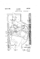
The preferred embodiment ot the invention .2a is illustrated by the accompanying drawings, of which Fig. 1 is a side elevation with one side wall of the casing and one ot the partition plates removed, the movable parts being shown in their normal positions; Fig.'2, a section on the line 2--2 ot Fig. 1; Fig. 3, a view similar to Fig. 1, the operative parts being shown in their actuated positions; and Fig. 4, a fragmentary detail view, partly in section, of the entrance blocking lever and associated parts.
The slug ejector may be vhoused in a suitable casing in which the parallel partition plates 1. and 2, shown clearly by Fig. 2, are mounted. lThe plates 1 and 2 are held in spaced relation by the guides 3, which form an entrance passageway 4 with which the deposit slot 5 communicates; a coin passageway 6 into which coins are directed and a slug passageway 7 into which slugs are directed.
The apparatus includes a selecting beam 8 pivotally mounted as indicated at 9 in the path of downwardly moving coins and slugs. The beam 8 is supported in the normal position shown by Fig. 1 by the pin l0 extending through the slot 11 in the partition plate. 1. The beam has a curved finger 8a and a normall inclined upper edge 8b to form a track for ownwardly moving coins and slugs. Pivoted at 12 adjacent the deposit slot 5 55 1s the entrance blocking lever 13. This lever has a laterally bevelled head 13a for a purose which will hereinafter appear, and an` inclined edge 13 b-to form a track for down- Wardlymoving coins and slugs. Mounted on the horizontal arm 13o at the lower end of this lever is the roller 14 having peripheral teeth.
To limit the rotation of the blocking lever 13I and roller 14 the invention provides the stop member 15 having a tooth 15a .toengage 65 said roller. This stop member is pivoted at 16 so that it may be held in various positions by the set screw 17 fitting in the arcuate slot 15b.
Pivote'd at 18 below the parts just re- 7 ferred to is the coin passageway gate 19. rIjhe pivot pin 18 extends through the partition plate 1, as shown by Fig. 2, and the beam actuating lever 20 is non-rotatably mounted on this pin on the outside of the partition plate 1. In Figs. 1 and 3, the partition plate 1 has beenremoved and the beam 2O remounted on the pin 18, for convenience in illustration. Tt will be understood that when the parts are assembled for operation, '80 lever 20 will be disposed on the outside o the plate 1 and the other elements above referred to on the inside of said plate, as indicated by Fig. 2.
The gate 19 has a cam 19a normally extending into the slot 21a of the actuating bar 21. This bar is connected to a suitable handle, no t shown, accessible from the exterior of the casing. It is guided in its reciprocatory movement by the pins 22 and 23 90 carried by the partition plate 1 and extending through slots 2lb and 21o.
Coins of the proper denomination deposited in the ejector are directed tothe coin passageway 6 wh'ch may lead to any desired 95 destination, such as the coin-controlled mechanism of a vending machine, money changer, or the like.
Attention is now invited to Fig. 41 which v illustrates the automatic operation of the 1 parts whereby a proper coin is directed to the coin passageway 6. When such a coin C is inserted in the deposit slot 5, it falls into the entrance passageway 4, rolls down and ofi the inclined edge 13b of the entrance blocking lever 13 and upon the concave finger 8a of the selecting beam 8. Rebounding from said finger, it then rolls down the inclined edge 8b of the selecting beam against the roller 14.
The size of the roller 14 and its disposition with respect to the beam 8 are such that the coin and roller come into Contact at a point below the center of gravity of the coin. When, after such contact, the coin continues to roll in an anti-clockwise direction down the edge of the beam, carrying the roller with it, the roller rotates in a clockwise direction, so that practically no resistance is offered to the free rotation of the coin until the roller strikes the tooth 15a of the stop member 15. `The stop member prevents all further movement of the roller by the coin. Robbed of its' inertia and acted upon by gravity, the coin thereupon moves downwardly, swinging the beam Sinto the position indicated at 8v', and falling oli' the same into the coin passageway 6. The position 8 of the beam is predetermined with respect to coin passageway 6.
The beam 8 is made movable by a proper coin into the position 8 by placing the fulcrum 9 a certain distance from the center of gravity of the beam; and by placing the adfjustable stop member 15 a certain. distance from the fulcrum 9. It will be obvious that rotation of the beam 8 is dependent not only on the weight of the coin, but also upon the distance between the fulcrum 9 and the point on the edge 8b to which the coin is permitted to roll. This distance may be varied by adjusting the stop niember 15.
The movement into the slug passageway 7 of a slug heavier than a coin of the proper Ieo tllenomination will now be described. See 1g. 1. A slug HS appreciably heavier than a proper coin will fall upon and rock the` beam 8 and then strike the roller14 and rebound into the slug passageway 7. The position into which the heavy slug may move the beam is indicated at 8". The exact position into which a certain heavy slug will move the beam will depend upon the weight of that slug. The beam may be rotated considerably more than indicated by the dotted lines 8. The position 8" is predetermined with respect to slug passageway 7.
Now' a slug LS appreciably lighter than a coin of the proper denomination falls upon and rolls down the inclined edge 8b of the selecting beam (Fig. 1) and moves the rollerv 14 into engagement with the stop member 15. Of insuliicient weight to rock the beam, the light slug is therefore `arrested and detained by the beam and roller. The detention of the light slugand the release of the coin is effected by adjustment of. the stop member 15. v
It is very ditlicult to cause the light slug to fall'into the coin passageway 6 by shaking the machine, because the point of contact between the roller 14 is below the center of slug, light slug has a greater tendency to climb the roller than to depress the beam.
The light slug, it will be understood, moves the entrance blocking lever into the position indicated in dottedlines at 13 so that the gravity of the light so that when the ejector is shaken the and the light slug y head 13a of the entrance blocking lever 13 posit slot 5 will be directed by the head 13a into the overflow passageway 24, (Figs. 1 and 4) which may be made to communicate with the slug passageway 7.
When an attempt is made to operate the machine with which the slug ejector is being used, by depressing the operating handle, not shown but hereinabove referred to, the actuating bar 21 is moved@ downwardly. When the bar 21 is moved downwardly, the gate 19 is lirst moved over the coin passageway, and then the beam 20 strikes the pin 10 and rocks the selecting beam 8. The position of the parts before the actuating bar 21 is moved is shown by Fig. 1, the position of the parts after the actuating bar has been moved downwardly is shown by Fig. 3. It will be apparent that the light slug( is not released until the gate 19 is closed, so that the light slug cannot enter the coin passageway 6 and therefore must enter the slug passageway 7.
When-the light slug is released, the lever 13 will be swung back by gravity to the normal position shown by Fig. 1 so that the entrance passageway 4 will automatically be opened.
Means are provided to automatically return the operating handle (not shown), to its normal position, when it is released by the operator, so that the bar 21 is moved to its normal position and thel gate 19 and lever 2O `are permitted to swing from the positions shown by Fig. 1.
Now if a slug MS containing iron is inserted, it will be detained by the magnet M.
Fig. `3 to the positions shown by During the detention of the slug MS by thev N ow if ,the operating handle, not shown, 1:,J
,i l l y y 1,859,725
is actuated, the.parts will'be moved from the positions shown b Fig. 1 to the positions shown by Fig. 3, w ereby the slug MS is swept from the magnet M into the sliig passagewayi 7, and the slu AS is forced upward- 1y on the edge 13b o the blocking lever 13 where it will temporarily be supported by thel linger 8a pf the selecting beam 8. When the parts are permitted to return to the normal positions illustrated by Fig. 1, the fin- -ger 8a releases the slug AS so that it falls upon the edge 8b. If the slug AS is heavier than the proper coin, it will rock the beam 8' into the dotted line position 8 and fall from it into the slug passageway 7 if lighter, it will be detained by the beam 8 and the roller 14,
and thereafter discharged through the slug n passagewa 7 by manualopera-tionofthe parts as hereina ove described;,and if magnetic,
it will not be detained by the magnet M be-V tained by the slug MS and the blocking lever,
and nally released and dropped into the`coin passageway when the parts are manually op-l erated to dispose of the slug MS.
The invention is not limited tothe preerred embodiment shown. Various changes in construction may be made within the scope of the following. claims.
I claim: t Y
`1. Coin apparatus having a deposit passageway, an entrance passageway, an overiiow passageway, said passageways being defined by substantially parallel walls, an entrance blocking lever pivoted to rock in a plane substantially parallel with said walls and to be swung into a predetermined position by a slug in said entrance passageway to cause movement of deposited coins and slugs in a direction substantially at a right angle to said wallsaiid into said overflow passa eway. i
2. 0in apparatus having .a deposit passageway, an entrance passageway, an overiiow passageway, said passageways being deiined by substantially parallel walls, an entrance blockin lever pivoted to rock inv a plane substantially parallel with said walls, and having an inclined head to be swung into a predetermined position by a slug in said entrance passageway-to cause movement ofdeposited coins and slugs in a direction substantially at a right angle to said walls and into said over-iiow passageway. l Y
3. A slug ejector having a pivoted coin selecting beam, said beam having an edge forming a track for coins and slugs, and a device disposed with respect to said beam to engage a light slug on said edge at a point below the center4 of gravit of said slug and Y limit the movement of sai slug on said edge,
siid beam and device serving to hold said. s ug.
4. A slug ejector having a pivoted coin selecting beam, said beam having an edge forming a track for coins and slugs, and a device mounted in a predetermined position with respect to said beam to engage a light slug on said edge at a point below the center of gravity of said slug, and lyieldably resist movement of said slug on said edge in one direction, said beam and device serving'to hold said slug.
5. A slug ejector having a pivoted coin selecting beam, said beam having an edge forming a track for coins, a device mounted -in a predetermined position with respectto said beam to engage a coin on said edge at a point below the center of gravity 'of said coin, and yieldably resist the movement of said coin on said edge in one direction, and means to cause said device to positively prevent movement of` said coin in said direction.'
6. A slug ejector having a pivoted coin selecting beam, said beam having an edge forming a track for coins, a device mounted in a predetermined position with respect to said beam to engage a coin on said edge at a point below the center of gravity of said coin, and yieldably resist the movement of said coin on said edge inu one direction, and means to cause said device to positively prevent movement of said coin in said direction, saidv means being adjustable with respect t0 said/100 beam. v l
7. A' slug ejector having a pivoted coin selecting beam, said beam having an edge 4forming a track for coins and slugs, and a roller mounted in a predetermined position lwith respect to said beam to engage and yieldably resist movement of a light slug on said edge in one direction, saidbeam and roller serving to hold said slug.`
' 8. A slug ejector having a.- pivoted coin selecting beam, said beam having an edge forming a trackvfor coins and slugs, and aroller mounted in a predetermined position with respect to said beam to engage a light slug on said edge at a point below the center 1 1! of gravity of said slug, and yieldably resist movement of said-.slug on said edge in one direction, said beam and hold said slug.
9.`A slug ejector having a pivoted coin selecting beam, said beam having an edge forming a track for coins, a roller mounted* in., a predetermined position with respect to said beam to engage and yieldably resistA movement of a coin on said edge in one direction, and a stop member to stop rotation of said roller and cause said rollerv to positively prevent movement of said coin in said direction. l
10. A slug ejectorhaving a pivoted coin roller serving to selectingV beam said beam having an edge forming a track for coins, a roller mounted in a predetermined position with respect to said beam to engage and yieldably resist movement of a com on said edge in one di-` j coin on said edge in one direction, and a stop member to stop rotation of said roller and cause said roller to positively prevent movement of said coin in said direction.
12. A slug ejector having a pivoted coin selecting beam, said beam having an edge forming a track for coins, a roller mounted in a redetermined position with respect to said Ilieam to engage a coin on said edge at a point below the center of gravity of said coin, and yieldably resist the movement of said coin onsaid edge in one direction, and
` a stop member to stop rotation of said roller and cause said roller to positively prevent movement of said coin in said direction, said member being adjustable with respect to said beam.
13. A slug ejector having a pivoted coin selecting beamfsaid beam having an edge forming a track for coins, a roller having peripheral teeth and mounted in a predetermined position with res ect to said beam to engage a coin on said e ge at a point below the center of gravity of said coin, and yieldably resist movement of said coin on said edge in one direction, and a stop member having a tooth to engage the teeth of said roller, stop rotation. of said roller, and cause said roller to positively prevent movement of said coin in said direction.
14. A slug ejector having a selecting beam, said beam having an edge forming a track for coins, a roller having peripheral teeth and mounted in a predeterminedy position with respect to said beam to engage a coin on said edge at a point below the center ogravity of said coin, and yieldably resist movement of said coin on said edge in on'edirection, and a stop member "having a tooth to engage Vthe teeth of said roller, stop rotation of said roller, and cause said! roller to positively prevent movement of'` said coin in said direction, said member being adjustable with respect to said beam.
15. A slug ejector having an entrance passageway, a pivoted coin selecting beam, said beam having an edgeforining a track for coins and slugs, an entrance blocking lever,
pivoted coin and a device carried by said lever to engage and yieldably resist movement of a lig t Slug on said edge in one direction said beam and roller serving to hold said slug.
17. A slug ejector having an entrance passageway, a, pivoted coinselecting beam, said beam having an edge forming a track for coins and slugs, an entrance blocking lever, and a roller carried by saidvlever to engage a llght slug on said edge at a point below the center of gravity of said slug, and yieldably resist movement of said slug on said edge in one direction, said beam and roller serving to hold said slug.
18. A slug ejector having an entrance passageway, a pivoted coin selecting beam, said beam having an edge forming a track for coins, an entrance blocking lever, and a device carried by said lever to engage a coin on said edge at a point below the center of gravity of said coin, and yieldably resist movement of said coin on said'edge in one direction, and means to cause said device to positively prevent movement of said coin in said directlon.
19. A slug ejectorhaving an entrance passageway, a pivoted coin selecting beam, said beam having an edge forming a track for coins, an entrance blocking lever, and a device carried by said lever to engage a coin on said edge at a point below the center of gravity of said coin, and yieldably resist movement of said coin on said edge in one direction, and means to cause said device to positively prevent movement of said coin 1n said direction, said means being adjustable with respect to said beam.
20. A slug ejector having an entrance passageway, a pivoted coin selecting beam, said beam having an edge forming a track for coins, an entrance blocking lever, a roller carried by said lever to engage and yieldably resist movement of a coin on said edge in one direction, and a stop member to stop rotation of said roller and cause said rollerto positively prevent movement of said coin in said direction.
21. A slug ej ectox` having an entrance passageway, a pivoted coin selecting beam, said beam having an edge forming a track for coins, an entrance blocking lever, a roller carried by said lever to engage and yieldably resist movement of a coin on said edge-in one of said roller and cause said roller to posiaanwas tively prevent movement of said coin in said direction, said member being adjustable with respect to said beam.
22. A slug ejector having an entrance passageway, a pivoted coin selecting beam below sald entrance passagewa a coin passageway and a slug passageway be ow said beam, a pivoted entrance blocking lever, a roller carried by said lever adjacent said beam and forming with said beam lighter slug arresting means, and movable by an arrested light slug to cause said lever to move into said entrance passageway, and an actuating member to move said beam and thereby release arrested light slugs and direct the same into said slug passageway.
23. A slug ejector having an entrance passageway, a pivoted coin selecting beam below said entrance passageway, a coin passageway and a slug passageway below said beam, a pivoted entrance blocking lever a roller carried by said lever adjacent said beam and Aforming with said beam lighter slug arresting means, and movable by an arrested light slug to cause said lever to move into said entrance passageway, a stop member to limit the movement of said roller by said slug, said member being adjustable with respect to said beam, and an actuating member to move said beam and thereby release arrested light slugs and Vdirect the same into said slug passageway.
24. A slug ejector having an entrance passageway, a pivoted coin selecting beam below said passageway, a coin passageway and a slug passageway below said beam, said beam being rotatable by coins of a predetermined weight te direct said coins into said coin passageway and rotatable lay heavier slugs to direct said slugs into sai slug passageway, a pivoted lever, a roller carried by said lever adjacent said beam and serving with said beam to detain lighter slugs, and an actuating member to move said beam whereby lighter slugs detained by said beam and roller may be released and directed into said slug passageway.
25. `A slug ejectorl having an entrance pas-y sageway, a plvoted coin selecting beam below said passageway, a coin passageway and a slug passageway below said beam, said beam being rotatable by coins of a predetermined weight to direct said coins into said coin passageway and rotatable b heavierslugs to direct said slugs into sai slug passageway, a pivoted lever, a roller carried by said lever adjacent said beam and serving with said beam to detain lighter slugs, a stop member to limit the movement of said roller by said slug, said member being adjustable with respect to said beam, and an actuating member to move said beam whereby lighter slugs detained by said beam and roller may be re,
leased and directed into said slug passageway.
26. A slug ejector having an entrance passageway, a pivoted coin selecting beam below slug passageway below said beam, said beam being rotatable by coins of a predetermined weight to direct said coins into said coin passageway, and rotatable by heavier slugs to direct said slugs into said slug passageway, an entrance blocking lever, a roller carried by said lever and forming with said beam arresting means for lighter slugs and movable by a lighter slug to cause said lever to enter said entrance passageway to block the same, and means to release arrested lighter slugs and direct the same into said slug passageway.
27. A slug ejector having an entrance passageway, a pivoted coin selecting beam below said passageway, a coin passageway and a slug passageway below said beam, said beam being rotatable by coins of a predetermined weight to direct said coins into said coin passageway, and rotatable by heavier slugs to direct said slugs into Isaid slug pasageway, an entrance blocking lever, a roller carried by said lever and forming with said beam arresting means for lighter slugs and movable by a lighter slug to cause said lever to enter said entrance passageway to block the same, a stop member to limit the movement of said roller vby said slug, said member being adjustable with respect to said beam, and means to release arrested lighter slugs and direct the same into said slug passageway.
28. A slug ejector having an entrance passageway, a coin selecting beam, an entrance blocking lever, and a roller carried by said lever adjacent said beam, said beam and roller being constructed and disposed to release a coin of a predetermined weight, and to retain a slug l1 hter than said coin, said roller being movable by said slug to cause said lever to enter said passageway and block the same.
29. A'slug ejector having an entrance passageway, a coin selecting beaman entrance blocking lever, a roller carried by saidV lever adjacent said beam, ysaid beam .and roller being constructed and disposed to release a com of a predetermined weight, and to retain a slug li hter than said coin, said roller being movab e by said slug to cause said lever to entersaid passageway and blockthe same, and a stop member to limit the movement of said roller by said slug, said member being adjustable with respect to said beam.
30. A slug ejector having an entrance passageway, a' coin selecting beam, a blocking lever, a roller carried by said lever adjacent 'IISv said beam, said beam and roller being con- A sageway, a coin selectm beam, a blockmg itc lever, a roller carried by said lever adjacent said beam, said beam and roller being constructed and disposed to release a coin of a predetermined weight and retain a slug lighter than said coin, said roller being movable by said slug to cause said lever to enter said passageway and block the same, a stop member to limit the movement by said roller of said slug, said member being adjustable 10 with respect to said beam, and means to cause said beam to release said slug.
32. A slug ejector having an entrance passageway, a coin selecting beam, a magnet mounted to arrest magnetic slugs, means to cause said beam to sweep said magnet, and an entrance blocking lever mounted to be movable into said entrance lpassageway by a coin or slug inserted during the detention by j said magnet of a magnetic slug.
33. A slug ejector having an entrance passageway, a coin selecting beam, a magnet mounted to arrest magnetic slugs, means to cause said beam to sweep sai magnet, and an entrance blockinglever mounted to direct magnetic slugs to said magnet, and to be movable-into said entrance passageway by a coin or slug inserted during the detention by said magnet of a magnetic slug.
34. A slug ejector having an entrance passageway, a magnet mounted to arrest magnetic slugs, the poles of said magnet being directed downwardly, a coin selecting beam pivoted below and adapted to sweep said magnet, and an entrance blocking lever mounted to be movable into said entrance passageway by an additional magnetic slug inserted during the detention by said magnet of a magnetic slug, and means to cause said beam to sweep sa1d detained slug from said magnet and prevent detention by said magnet of said additional slug.
v 35. A slug ejector having an entrance passageway, a coin passageway, and a slug passageway, la pivoted coin selecting beam, and
a coin passageway gate and a beam actuating lever rigidly connected together and rotatable about a common axis, so that when they are 'rotated together on said axis said gate lirst closes sa1d entrance passageway and said lever then rocks said beam.
In testimony whereof, I hereunto aix my signature.
ALBERT S. ROSS.
Priority Applications (1)
| Application Number | Priority Date | Filing Date | Title |
|---|---|---|---|
| US430506A US1852725A (en) | 1930-02-24 | 1930-02-24 | Slug ejector |
Applications Claiming Priority (1)
| Application Number | Priority Date | Filing Date | Title |
|---|---|---|---|
| US430506A US1852725A (en) | 1930-02-24 | 1930-02-24 | Slug ejector |
Publications (1)
| Publication Number | Publication Date |
|---|---|
| US1852725A true US1852725A (en) | 1932-04-05 |
Family
ID=23707835
Family Applications (1)
| Application Number | Title | Priority Date | Filing Date |
|---|---|---|---|
| US430506A Expired - Lifetime US1852725A (en) | 1930-02-24 | 1930-02-24 | Slug ejector |
Country Status (1)
| Country | Link |
|---|---|
| US (1) | US1852725A (en) |
Cited By (2)
| Publication number | Priority date | Publication date | Assignee | Title |
|---|---|---|---|---|
| US3197009A (en) * | 1961-10-19 | 1965-07-27 | Nat Rejectors Gmbh | Coin separators |
| US4544058A (en) * | 1984-04-04 | 1985-10-01 | Nathan Choderker | Coin acceptor |
-
1930
- 1930-02-24 US US430506A patent/US1852725A/en not_active Expired - Lifetime
Cited By (2)
| Publication number | Priority date | Publication date | Assignee | Title |
|---|---|---|---|---|
| US3197009A (en) * | 1961-10-19 | 1965-07-27 | Nat Rejectors Gmbh | Coin separators |
| US4544058A (en) * | 1984-04-04 | 1985-10-01 | Nathan Choderker | Coin acceptor |
Similar Documents
| Publication | Publication Date | Title |
|---|---|---|
| US1852725A (en) | Slug ejector | |
| US2116309A (en) | Coin chute | |
| US1948107A (en) | Multiple coin actuated vending machine | |
| US1926232A (en) | Coin operated mechanism | |
| US1503223A (en) | Coin detector for vending machines | |
| US2262425A (en) | Coin return | |
| US2118425A (en) | Coin detecting device for slot machines | |
| US2288835A (en) | Coin chute | |
| US1630427A (en) | Slug detector for coin-controlled machines | |
| US1817076A (en) | Coin-controlled mechanism | |
| US1764985A (en) | Slug ejector | |
| US2082533A (en) | Coin controlled vending machine | |
| US1802488A (en) | Coin-controlled operating mechanism for vending machines | |
| US1782666A (en) | Money changer | |
| US1749986A (en) | Slug ejector | |
| US2038069A (en) | Coin controlled apparatus | |
| SU19840A1 (en) | Item Dispenser | |
| US1965858A (en) | Means for preventing clogging of coin controlled devices | |
| US1421831A (en) | Vending machine and the like | |
| US2216811A (en) | Coin operated vending machine | |
| US2230607A (en) | Coin-controlled dispensing mechanism | |
| US1633234A (en) | Coin chute | |
| US2395279A (en) | Coin selector device | |
| US1782250A (en) | Coin-controlled apparatus | |
| US1807175A (en) | Coin actuated change mechanism |