US1852724A - Fluid operated tool - Google Patents
Fluid operated tool Download PDFInfo
- Publication number
- US1852724A US1852724A US486306A US48630630A US1852724A US 1852724 A US1852724 A US 1852724A US 486306 A US486306 A US 486306A US 48630630 A US48630630 A US 48630630A US 1852724 A US1852724 A US 1852724A
- Authority
- US
- United States
- Prior art keywords
- valve
- chamber
- piston
- distributing
- plug
- Prior art date
- Legal status (The legal status is an assumption and is not a legal conclusion. Google has not performed a legal analysis and makes no representation as to the accuracy of the status listed.)
- Expired - Lifetime
Links
Images


Classifications
-
- B—PERFORMING OPERATIONS; TRANSPORTING
- B25—HAND TOOLS; PORTABLE POWER-DRIVEN TOOLS; MANIPULATORS
- B25D—PERCUSSIVE TOOLS
- B25D9/00—Portable percussive tools with fluid-pressure drive, i.e. driven directly by fluids, e.g. having several percussive tool bits operated simultaneously
- B25D9/14—Control devices for the reciprocating piston
- B25D9/16—Valve arrangements therefor
- B25D9/20—Valve arrangements therefor involving a tubular-type slide valve
-
- B—PERFORMING OPERATIONS; TRANSPORTING
- B25—HAND TOOLS; PORTABLE POWER-DRIVEN TOOLS; MANIPULATORS
- B25D—PERCUSSIVE TOOLS
- B25D2209/00—Details of portable percussive tools with fluid-pressure drive, i.e. driven directly by fluids, e.g. having several percussive tool bits operated simultaneously
- B25D2209/005—Details of portable percussive tools with fluid-pressure drive, i.e. driven directly by fluids, e.g. having several percussive tool bits operated simultaneously having a tubular-slide valve, which is coaxial with the piston
Definitions
- the present invention has relation more particularly to a hammer tool for automatically striking a single blow; a succession of blowsrequiring the manual operation of a control by the operator of the tool. It is particularly adapted for breaking up small bodies of ore or the like, permitting its removal from mines. It is the usual practice to deliver the material to a grizzly or screen through which it passes to the mine car. Obviously rocks or lumps of a size too great to pass through the screen or grizzly will lodge therein and it is the custom for a workman to break these chunks with a sledge hammer into pieces small enough to pass through the screen. The present invention is applicable for this purpose of breaking the rock and it has been found it will strike a much harder blow than can be delivered by a sledge, and
- the principal object, therefore, of the present invention is to provide a novel and eifective tool of this character and for such purposes as above outlined.
- a further and important object is to provide a novel, simple and effective distributing valve mechanism peculiarly useful for the defined purposes, but also applicable quite generally to fluid actuated tools.
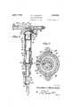
- Figure 1 is a view in elevation of the preferred embodiment of the invention.
- Figure 2 is a longitudinal sectional view on the line 2-2 of the Figure 1 showing the valve chest in elevation.
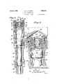
- Figure 3 is a longitudinal sectional view at right angles to Figure 2. on an enlarged scale and including in the section the distributing valve.
- Figure 4 is a sectional view on the line H of Figure 3.
- Figure 5 is a sectional view on the line 5-5 of Figure 4.
- Figure 6 is a longitudinal sectional View through the cylinder member alone.
- Figure 7 is a lower end view of the same.
- Figure 8 is a view in rear elevation of the plug member.
- Figure 10 is an end view of the valve chest, parts being broken away.
- Figure 11 is a longitudinal sectional view on the line 1111 of Figure 10.
- Figure 12 is a sectional view on the line 1212 of Figure 11.
- Figure 13 is a longitudinal sectional view through the distributing valve.
- Figure ll is an end elevation of said valve.
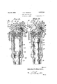
- Figure 15 is a longitudinal sectional view through the tool, diagrammatic in its charactor and illustrating the relation of the parts on the initiation of operation of the tool.
- Figure 16 is a view similar to Figure 15 but showing the tool when the piston is at the beginning of its working or downward structure.
- a cylinder member is employed that is in the form of a barrel 17
- This barrel has a longitudinal bore that forms a piston chamber 18.
- the front end of said bore is reduced as shown at 19, while the rear end portion of the bore is enlarged or counter-bored as shown at 20.
- Coupled to the front end of the barrel 17 by a collar 21 is a chuck 22 designed to receive the hexagonal or other shaped shank 24 of a breaking steel or tool 25.
- this steel has a collar 26 located behind a tool retainer 27 which allows the tool or steel to have a limited longitudinal movement in the chuck while preventng its complete disengagement therefrom.
- a piston 28 is mounted to reciprocate in the piston chamber 18 and has a forward reduced hammer extension 29 operating in the portion 19 of the barrel, said hammer extension being adapted to strike the rear end or shank 24: of the breaking steel.
- the counter-bore contains a distributing valve.
- a cylindrical plug forming a valve support and designated 30 is located longitudinally in the counter-bore and is of smaller diameter than the same.
- This plug has at its lower end a flange or head 31 that snugly fits into the lower end of the counterbore 20.
- Fitted into said counter-bore above the flange 31 and bearing against its margin is a valve chest sleeve 32 which extends to the rear end of the counter-bore.
- the internal diameter of this chest is greater than the external diameter of the plug except at its upper end where said chest has an internal flange 33 snugly fitted to the upper end of the plug 30.
- the space formed between the plug and chest constitutes a valve chamber 34. In this chamber is a reciprocatory tubular distributing valve 35 sliding on the plug 30 and on the interior of the chest.
- a disc or washer 36 Abutting the rear end of the barrel 17 and extending over the rear end of the valve chest is a disc or washer 36 which in turn is borne against by a rear head 37 formed with oppositely extending hand grips 38.
- a nipple 39 On one side of the head 37 is formed a nipple 39 into which is screwed a coupling 40 for a supply hose that is, of course, intended to bring motive fluid, such as air under pressure, to the tool.
- the nipple 39 is therefore provided with a bore 40A and said bore is formed with a valve seat 41.
- the bore communicates with a port 42 that opens into a chamber 43 formed in the lower end of the back head 37.
- This chamber 43 is in open communication with here 44 formed longitudinally in the plug 30. It will be noted that the bore 44 does not extend entirely through the plug so that it is shut off from the piston chamber 18.
- Said flange 31 has, outside the plug 30, distributing ports 49 that open from the bottom of the valve chamber 34 into the top of the piston chamber 18.
- the walls of the barrel or cylinder member 17 are also provided with one or more longitudinal distributing passageways 50 that open into the lower end of the piston chamber 18 and at their upper ends communicate with ports 51 opening through the valve chest into the upper end of the valve chamber 34. These ports communicate with an interior annular groove 52 formed in the upper end of the valve chest 32.
- Said valve chest also has an intermediate annular groove 53 from which opens one or more exhaust ports 54 extending through the valve chest and barrel to atmosphere.
- the lower end of the valve chest 32 has an annular groove or chamber 55 and the distributing valve 35 has an outstanding annular flange 56 that reciprocates in the chamber 55.
- the valve 35 eX- ternally has a relatively wide, shallow groove 57 that alternately provides a means of communication between the groove 52 and groove 53, and between the groove or chamber 55 and said groove 53, as the valve is reciprocated.
- the supply passageway 40 is controlled by a valve 60 which cooperates with the valve seat 41 to close the passageway and is urged to said seat by a spring 61 bearing against it. It has a stem 62 slidable in the head 37 and borne against by a lug 63 on a hand lever 64, pivoted at 65 in the head.
- This hand lever has a grip portion 66 that lies along one of the handles 38 and is adapted to be pressed into the same by the operator holding the handles 38.
- the operation of the structure may be outlined as follows:
- the tool is intended to be held in a substantially upright or upstanding position with the steel on the rock to be broken or other material to be operated on.
- the parts are substantially shown in Figures 2 and 3, that is to say the piston 28 is at the bottom of the piston chamber 18, the distributing valve 35 is the bottom or" its chamber 34 and the throttle valve 60 is closed.
- the Operaator holding the tool by the handles 38 presses downwardly on the grip 66 he opens the throttle valve 60. Therefore air or other fluid under pressure will enter the chamber 43 and the bore 44 of the plug 30.
- the comb nation with a cylinder member having a piston chamber and a reciprocatory piston operating in the chamber, of means including an automatic distributing valve for distributing fluid alternately to the piston chamber on opposite s des of the piston, said means automatically stalling the valve and thereby the piston at the completion of each reciprocation. and a manual valve for controlling the motive fluid supply to the distributing means.
- a fluid operated tool the combination with a cylinder member adapted to be maintained in a generally upright position and having a longitudinally disposed piston chamber and a reciprocatory piston operating in the chamber, of means including an automatic distributing valve for distributing flu d alternately to the piston chamber on opposite sides of the piston, said means automatcially stalling the valve and thereby the piston at the completion of each downward stroke, and a manual vale for controlli.
- a fluid operated tool the combination with a cylinder member having a piston chamber and a piston that reciprocates in the chamber, of a distributing valve chamber, distributing passageways leading from the valve chamber to the piston chamber on opposite sides of the piston, an exhaust passageway leading from the valve, chamber, a motive fluid supply passageway leading to the valve chamber, a throttle valve controlling the supply passageway, and an automatic distributing valve in the valve chamber for alternately allowing communication between the supply passageway and the distributing passageways and for connecting one of the distributing passagesways to the exhaust passageway while withholding at all times communication between the other distribut ng passageway and the exhaust to maintain pressure in the piston chamber and against one end of the piston to thereby hold the piston until the throttle valve is closed.
- a cylinder member having a piston chamber and a piston that rec procates in the chamber. of a distributing valve chamber, distributing passageways leading from thevalve chamber to the piston chamber on opposite sides of the piston, an exhaust passageway leading from the valve chamber, a motive fluid supply passageway leading to the valve chamber, a throttle valve controlling the supply passageway and an automaticdistributing valve n the valve chamher for alternately allowing communication between the supply passageway and the distributing passageways and for connecting one of the distributing passageways to the exhaust passageway while withholding at all times communication between the other distr buting passageway and the exhaust to maintain pressure in the piston chamber and against one end of the piston to thereby hold the piston until the throttle valve is closed.
- said valve having a pressure face open at all times to the end of the piston chamber in which pressure is thus maintained and such pressure acting on the face to hold the valve against further automat c movement and prevent further distribution of the fluid until the throttle valve is closed and again opened.
- a fluid operated tool the combination with a cylinder member having a piston chamber and a piston that reciprocates in the chamber, said cylinder being maintained substantially vertical during the operation of the tool, a distributing valve chamber, distributing passageways leading from the valve chamber to the piston chamber on opposite sides of the piston, an exhaust passageway leading from the valve chamber, a motive fluid supply passageway leading to the valve chamber, a throttle valve controlling the supply passageway, and an automatic distributing valve in the valve chamber for alternately allowing communication between the supply passageway and the distributing passageways and for connecting one of the distributing passageways to the exhaust passageway while withholding at all times communication between the other distributing passageway and the exhaust to maintain pressure in the piston chamber and against the upper end of the piston to thereby hold the piston in its lowermost position until the throttle valve is closed.
- a fluid operated tool the combination with a cylinder member having a piston chamber and a piston that reciprocates in the chamber, said cylinder being maintained substantially vertical during the operation of the tool, a distributing valve chamber, distributing passageways leading from the valve chamber to the piston chamber on opposite sides of the piston, an exhaust passageway leading from the valve chamber, a motive fluid supply passageway leading to the valve chamber, a throttle valve controlling the supply passageway, and an automatic distributing valve in the valve chamber for alternately allowing communication between the supply passageway and the distributing passageways and for connecting one of the distributing passageways to the exhaust passageway while withholding at all times com munication between the other distributing passageway and the exhaust to maintain pressure in the piston chamber and against the upper end of the piston to thereby hold the piston in its lowermost position until the throttle valve is closed, said valve having a pressure face open at all times to the end of the piston chamber in which pressure is thus maintained and such pressure acting on the face to hold the valve-against further automatic movement and prevent further distributing of the fluid until the
- a fluid operated tool the combination with a cylinder member having a longitudinally disposed piston chamber and a longitudinally disposed valve chamber, the rear end of the former having direct connection with the front end of the latter, said cylinder being maintained substantially vertical during the operation of the tool, a reciproca-tory piston in the piston chamber, a distributing passageway leading from the valve chamber to the front end of the piston chamber, exhaust permitting means leading from the valve chamber, an exhaust passageway leading from the rear end of the piston chamber to the valve chamber, and a mo tive fluid supply passageway opening into the valve chamber, a throttle valve controlling the supply passageway, and an'automatic distributing valve in the valve chamber that is movable to a position to open the distributing passageway to the front end of the piston chamber and close the exhaust passageway from the rear end of the piston chamber and is also movable to a position to open the connection between the latters rear end and the valve chamber and close said exhaust passageway from the rear end, said distributing valve having a pressure surface that is operated on by the motive
- a fluid operated tool the combination with a cylinder member having a longitudinally disposed piston chamber, a valve chamber and a reciprocatory piston in the piston chamber, said cylinder being maintained substantially vertical during the operation of the tool, means for supplying motive fluid to the valve chamber, distributing passageways leading from the valve chamber to the piston chamber on opposite sides of the piston, and a distributing valve in the valve chamber for alternately directing motive fluid from the supply passageway to the distributing passageways, said valve having a pressure face operated on by motive fluid when introduced into the upper end of the piston chamber to hold the distributing valve in raised position as long as the motive fluid is supplied to the supply passageway by the open throttle valve, and thereby hold the piston at the bottom. of its downward stroke under the influence of said motive fluid, and said valve gravitating to its lower position to admit motive fluid to the lower end of the piston chamber when the throttle valve is closed and motive fluid is thereby cut oil from the valve chamber.
- a fluid operated tool the combination with a cylinder member having a piston cham ber and a piston operating therein, a valve chamber and distributing passageways leading from the valve chamber at spaced points to the piston chamber on opposite sides of the piston therein, of a plug extending into the piston chamber and having a motive fluid supply bore and lateral outlets at difl'erent points for respectively delivering motive fluid to the distributing passageways, and a distributing valve in the valve chamber and slidable on the plug to alternately establish and cut ofl' communication between the ports and distributing passageways.
- a fluid operated tool the combination with a cylinder member having a longitudinal bore, the front end portion of which constitutes a piston chamber, of a plug located in the rear end of the bore and of less diameter than the same, forming a distributing valve chamber, said plug having a supporting flange, forming a wall between the two chambers, said plug having a motive fluid supply bore with lateral ports opening through the peripheral wall at different distances from the ends of the plug, the flange of the plug having a port outside the plug forming a distributing passageway to the rear end of the piston chamber, said cylinder member also having a distributing passage way between the rear portion of the valve chamber and the front portion of the piston chamber, and a tubular valve that reciprocates on the plug and alternately closes the lateral ports therethrough.
- a fluid operated tool the combination with a cylinder member having a longitudinal bore, the front portion of which constitutes a piston chamber, the rear portion of said bore being enlarged, of a plug in said enlarged portion and of less diameter than the same, the front end of said plug having a flange that substantially fits the front end of the enlarged portion, a valve chest sleeve fitted into the enlarged portion of the bore behind the flange and having a bore of greater diameter than the plug, said flange having a port therethrough outside the plug for directing motive fluid to the rear end of the piston chamber, a distributing passageway leading from the rear portion of the valve chest to the front portion of the piston chamber, said plug having a motive fluid supply bore and lateral ports opening through the plug within the front and rear portions of the valve chest, and a tubular valve that is mounted to reciprocate in the plug and alternately open and close the lateral ports to thereby alternately supply and out off the motive fluid to the flange port and to the distributing passageway.
Landscapes
- Physics & Mathematics (AREA)
- Fluid Mechanics (AREA)
- Engineering & Computer Science (AREA)
- Mechanical Engineering (AREA)
- Portable Nailing Machines And Staplers (AREA)
Description
April 5, 1932.
"Z 66' F y, 1, 7 64b 38 a7 J L G. C. PEARSON FLUID OPERATED TOOL Filed Oct; 4, 1950 5 Sheets-Sheet 1 gwventoz Gas kw Pearson/ April 5, 1932. G. c. PEARSON FLUID OPERATED TboL Filed Oct. 4, 1930 5 SheetsSheet 2 gmantoc Gasiazz 611 660119010,
April 5, 1932. G. g. PEARSON FLUID OPERATED TOOL 5 Sheets-sl'leet 3 Filed Oct. 4, 1950 Filed Oct. 4, 1930 5 Sheets-Sheet 4 G. C. PEARSON FLUID OPERATED TOOL April 5, 1932.
5 Sheets-Sheet 5 Filed Oct. 4, 1930 Flip .15. 62 65 zjwuentoz 45 fig Gashwafkarsaw,
Patented Apr. 5, 1932 UNITED STATES PATENT QFFICE GUSTAV C. PEARSON, OI DENVER, COLORADO, ASSIGNOR TO GARDNER-DENVER COM- PANY, OF DENVER, GOLORADO, A CORPORATION OF DELAWARE FLUID OPERATED TOOL Application filed October 4, 1930. I Serial No. 486,306.
The present invention has relation more particularly to a hammer tool for automatically striking a single blow; a succession of blowsrequiring the manual operation of a control by the operator of the tool. It is particularly adapted for breaking up small bodies of ore or the like, permitting its removal from mines. It is the usual practice to deliver the material to a grizzly or screen through which it passes to the mine car. Obviously rocks or lumps of a size too great to pass through the screen or grizzly will lodge therein and it is the custom for a workman to break these chunks with a sledge hammer into pieces small enough to pass through the screen. The present invention is applicable for this purpose of breaking the rock and it has been found it will strike a much harder blow than can be delivered by a sledge, and
\ without the manual labor necessary to operate the latter. relations.
The principal object, therefore, of the present invention is to provide a novel and eifective tool of this character and for such purposes as above outlined.
A further and important object is to provide a novel, simple and effective distributing valve mechanism peculiarly useful for the defined purposes, but also applicable quite generally to fluid actuated tools.
In the accompanying drawings Figure 1 is a view in elevation of the preferred embodiment of the invention.
Figure 2 is a longitudinal sectional view on the line 2-2 of the Figure 1 showing the valve chest in elevation.
Figure 3 is a longitudinal sectional view at right angles to Figure 2. on an enlarged scale and including in the section the distributing valve.
Figure 4 is a sectional view on the line H of Figure 3.
Figure 5 is a sectional view on the line 5-5 of Figure 4.
Figure 6 is a longitudinal sectional View through the cylinder member alone.
Figure 7 is a lower end view of the same.
Figure 8 is a view in rear elevation of the plug member.
It is, of course, useful in other Figure 9 is a side elevation of the same.
Figure 10 is an end view of the valve chest, parts being broken away.
Figure 11 is a longitudinal sectional view on the line 1111 of Figure 10.
Figure 12 is a sectional view on the line 1212 of Figure 11.
Figure 13 is a longitudinal sectional view through the distributing valve.
Figure ll is an end elevation of said valve.
Figure 15 is a longitudinal sectional view through the tool, diagrammatic in its charactor and illustrating the relation of the parts on the initiation of operation of the tool.
Figure 16 is a view similar to Figure 15 but showing the tool when the piston is at the beginning of its working or downward structure.
In the embodiment disclosed a cylinder member is employed that is in the form of a barrel 17 This barrel has a longitudinal bore that forms a piston chamber 18. The front end of said bore is reduced as shown at 19, while the rear end portion of the bore is enlarged or counter-bored as shown at 20. Coupled to the front end of the barrel 17 by a collar 21 is a chuck 22 designed to receive the hexagonal or other shaped shank 24 of a breaking steel or tool 25. As shown this steel has a collar 26 located behind a tool retainer 27 which allows the tool or steel to have a limited longitudinal movement in the chuck while preventng its complete disengagement therefrom.
A piston 28 is mounted to reciprocate in the piston chamber 18 and has a forward reduced hammer extension 29 operating in the portion 19 of the barrel, said hammer extension being adapted to strike the rear end or shank 24: of the breaking steel.
The counter-bore contains a distributing valve. A cylindrical plug forming a valve support and designated 30 is located longitudinally in the counter-bore and is of smaller diameter than the same. This plug has at its lower end a flange or head 31 that snugly fits into the lower end of the counterbore 20. Fitted into said counter-bore above the flange 31 and bearing against its margin is a valve chest sleeve 32 which extends to the rear end of the counter-bore. The internal diameter of this chest is greater than the external diameter of the plug except at its upper end where said chest has an internal flange 33 snugly fitted to the upper end of the plug 30. The space formed between the plug and chest constitutes a valve chamber 34. In this chamber is a reciprocatory tubular distributing valve 35 sliding on the plug 30 and on the interior of the chest.
Abutting the rear end of the barrel 17 and extending over the rear end of the valve chest is a disc or washer 36 which in turn is borne against by a rear head 37 formed with oppositely extending hand grips 38. On one side of the head 37 is formed a nipple 39 into which is screwed a coupling 40 for a supply hose that is, of course, intended to bring motive fluid, such as air under pressure, to the tool. The nipple 39 is therefore provided with a bore 40A and said bore is formed with a valve seat 41. The bore communicates with a port 42 that opens into a chamber 43 formed in the lower end of the back head 37. This chamber 43 is in open communication with here 44 formed longitudinally in the plug 30. It will be noted that the bore 44 does not extend entirely through the plug so that it is shut off from the piston chamber 18.
Referring now to the back head 37 and handles 38, it will be noted that the supply passageway 40 is controlled by a valve 60 which cooperates with the valve seat 41 to close the passageway and is urged to said seat by a spring 61 bearing against it. It has a stem 62 slidable in the head 37 and borne against by a lug 63 on a hand lever 64, pivoted at 65 in the head. This hand lever has a grip portion 66 that lies along one of the handles 38 and is adapted to be pressed into the same by the operator holding the handles 38.
The operation of the structure may be outlined as follows: The tool is intended to be held in a substantially upright or upstanding position with the steel on the rock to be broken or other material to be operated on. When in such a position the parts are substantially shown in Figures 2 and 3, that is to say the piston 28 is at the bottom of the piston chamber 18, the distributing valve 35 is the bottom or" its chamber 34 and the throttle valve 60 is closed. It now the oprator holding the tool by the handles 38, presses downwardly on the grip 66 he opens the throttle valve 60. Therefore air or other fluid under pressure will enter the chamber 43 and the bore 44 of the plug 30. As the valve 35 is now at its lowermost position, the outlet ports 45 and groove 46 are in con1- munieation with the groove 52 so that this motive fluid will pass therethrough and through the passageway 50 to the lower end or" the piston chamber 18. Consequently the fluid will operate on the lower end of the piston 28 and elevate it. At this time it will be noted that the exhaust passageway 58 from the upper portion of the piston chamber 18 is open to atmosphere through the port 59, chamber 55, groove 57, groove 53, and exhaust port 54. Therefore there is no material resistance to the upward movement of the piston until it has passed the lower end of the passageway 58 that opens into the piston chamber 18. lVhen it has passed this point it begins to build up the pressure of the motive fluid trapped in the upper end of the piston chamber 18 and this fluid acting through the ports 49 and against the lower end of the distributing valve, including the flange 56 which provides a relatively large area, the distributing valve 35 is elevated, closing the ports 4.5 and groove 46 off from the groove 52. The further supply of motive fluid to the lower end of the piston chamber 18, is thus prevented. At the same time the lower end of the distributing valve 35 being elevated allows communication between the ports 47 and groove 48, and the Lil distributing ports 49, so that the motive fluid which enters the bore 44 of the plug now gains access to the upper end of the piston chamber 18 and operating on the upper end of the piston drives it downwardly on its working stroke. The fluid in advance of the piston escapes through the distributing passageway 50, ports 51, grooves 52, 57, and 53 to the exhaust port 54 and thence to atmosphere-all as indicated in Figure 16. When the piston 28 delivers its blow, the piston chamber 18 above it is, of course, filled with live air or other active motive fluid. The piston stops and cannot return because of this pressure upon it. Nor can the distributing valve drop because this same pressure is still against its lower end including the area of the flange 56. The tool, therefore, becomes non-active. The operator now permits the throttle valve to close by releasing the grip 66. When this occurs the live motive fluid is cut off from the distributing valve chamber and as the fluid under pressure in the upper end of the piston chamber 18 leaks out, the pressure therein becomes reduced so that the distributing valve 35 becomes unsupported and drops by gravity to its lowermost position. The operator can now reopen the throttle valve 60 and the above described operation will be repeated.
From the foregoing, it is thought that the construction, operation and many advantages of the herein described invention will be apparent to those skilled in the art without further description, and it will be understood that various changes in the size, shape, proportion and minor details of construction may be resorted to without departing from the spirit or sacrificing any of the advantages of the invention.
What I claim, is:
1. In a fluid operated tool, the comb nation with a cylinder member having a piston chamber and a reciprocatory piston operating in the chamber, of means including an automatic distributing valve for distributing fluid alternately to the piston chamber on opposite s des of the piston, said means automatically stalling the valve and thereby the piston at the completion of each reciprocation. and a manual valve for controlling the motive fluid supply to the distributing means.
2. In a fluid operated tool, the combination with a cylinder member adapted to be maintained in a generally upright position and having a longitudinally disposed piston chamber and a reciprocatory piston operating in the chamber, of means including an automatic distributing valve for distributing flu d alternately to the piston chamber on opposite sides of the piston, said means automatcially stalling the valve and thereby the piston at the completion of each downward stroke, and a manual vale for controlli.
the motive fluid supply to the distributing means.
3. In a fluid operated tool, the combination with a cylinder member having a piston chamber and a piston that reciprocates in the chamber, of a distributing valve chamber, distributing passageways leading from the valve chamber to the piston chamber on opposite sides of the piston, an exhaust passageway leading from the valve, chamber, a motive fluid supply passageway leading to the valve chamber, a throttle valve controlling the supply passageway, and an automatic distributing valve in the valve chamber for alternately allowing communication between the supply passageway and the distributing passageways and for connecting one of the distributing passagesways to the exhaust passageway while withholding at all times communication between the other distribut ng passageway and the exhaust to maintain pressure in the piston chamber and against one end of the piston to thereby hold the piston until the throttle valve is closed.
4. In a fluid operated tool, the combination with a cylinder member having a piston chamber and a piston that rec procates in the chamber. of a distributing valve chamber, distributing passageways leading from thevalve chamber to the piston chamber on opposite sides of the piston, an exhaust passageway leading from the valve chamber, a motive fluid supply passageway leading to the valve chamber, a throttle valve controlling the supply passageway and an automaticdistributing valve n the valve chamher for alternately allowing communication between the supply passageway and the distributing passageways and for connecting one of the distributing passageways to the exhaust passageway while withholding at all times communication between the other distr buting passageway and the exhaust to maintain pressure in the piston chamber and against one end of the piston to thereby hold the piston until the throttle valve is closed. said valve having a pressure face open at all times to the end of the piston chamber in which pressure is thus maintained and such pressure acting on the face to hold the valve against further automat c movement and prevent further distribution of the fluid until the throttle valve is closed and again opened.
5. In a fluid operated tool, the combination with a cylinder member having a piston chamber and a piston that reciprocates in the chamber, said cylinder being maintained substantially vertical during the operation of the tool, a distributing valve chamber, distributing passageways leading from the valve chamber to the piston chamber on opposite sides of the piston, an exhaust passageway leading from the valve chamber, a motive fluid supply passageway leading to the valve chamber, a throttle valve controlling the supply passageway, and an automatic distributing valve in the valve chamber for alternately allowing communication between the supply passageway and the distributing passageways and for connecting one of the distributing passageways to the exhaust passageway while withholding at all times communication between the other distributing passageway and the exhaust to maintain pressure in the piston chamber and against the upper end of the piston to thereby hold the piston in its lowermost position until the throttle valve is closed.
6. In a fluid operated tool, the combination with a cylinder member having a piston chamber and a piston that reciprocates in the chamber, said cylinder being maintained substantially vertical during the operation of the tool, a distributing valve chamber, distributing passageways leading from the valve chamber to the piston chamber on opposite sides of the piston, an exhaust passageway leading from the valve chamber, a motive fluid supply passageway leading to the valve chamber, a throttle valve controlling the supply passageway, and an automatic distributing valve in the valve chamber for alternately allowing communication between the supply passageway and the distributing passageways and for connecting one of the distributing passageways to the exhaust passageway while withholding at all times com munication between the other distributing passageway and the exhaust to maintain pressure in the piston chamber and against the upper end of the piston to thereby hold the piston in its lowermost position until the throttle valve is closed, said valve having a pressure face open at all times to the end of the piston chamber in which pressure is thus maintained and such pressure acting on the face to hold the valve-against further automatic movement and prevent further distributing of the fluid until the throttle valve is closed and again opened.
v7. In a fluid operated tool, the combination with a cylinder member having a longitudinally disposed piston chamber and a longitudinally disposed valve chamber, the rear end of the former having direct connection with the front end of the latter, said cylinder being maintained substantially vertical during the operation of the tool, a reciproca-tory piston in the piston chamber, a distributing passageway leading from the valve chamber to the front end of the piston chamber, exhaust permitting means leading from the valve chamber, an exhaust passageway leading from the rear end of the piston chamber to the valve chamber, and a mo tive fluid supply passageway opening into the valve chamber, a throttle valve controlling the supply passageway, and an'automatic distributing valve in the valve chamber that is movable to a position to open the distributing passageway to the front end of the piston chamber and close the exhaust passageway from the rear end of the piston chamber and is also movable to a position to open the connection between the latters rear end and the valve chamber and close said exhaust passageway from the rear end, said distributing valve having a pressure surface that is operated on by the motive fluid to hold the valve in its latter position and stop the piston at the bottom of its stroke.
8. In a fluid operated tool, the combination with a cylinder member having a longitudinally disposed piston chamber, a valve chamber and a reciprocatory piston in the piston chamber, said cylinder being maintained substantially vertical during the operation of the tool, means for supplying motive fluid to the valve chamber, distributing passageways leading from the valve chamber to the piston chamber on opposite sides of the piston, and a distributing valve in the valve chamber for alternately directing motive fluid from the supply passageway to the distributing passageways, said valve having a pressure face operated on by motive fluid when introduced into the upper end of the piston chamber to hold the distributing valve in raised position as long as the motive fluid is supplied to the supply passageway by the open throttle valve, and thereby hold the piston at the bottom. of its downward stroke under the influence of said motive fluid, and said valve gravitating to its lower position to admit motive fluid to the lower end of the piston chamber when the throttle valve is closed and motive fluid is thereby cut oil from the valve chamber.
9. In a fluid operated tool, the combination with a cylinder member having a piston cham ber and a piston operating therein, a valve chamber and distributing passageways leading from the valve chamber at spaced points to the piston chamber on opposite sides of the piston therein, of a plug extending into the piston chamber and having a motive fluid supply bore and lateral outlets at difl'erent points for respectively delivering motive fluid to the distributing passageways, and a distributing valve in the valve chamber and slidable on the plug to alternately establish and cut ofl' communication between the ports and distributing passageways.
10. In a fluid operated tool, the combination with a cylinder member having a longitudinal bore, the front end portion of which constitutes a piston chamber, of a plug located in the rear end of the bore and of less diameter than the same, forming a distributing valve chamber, said plug having a supporting flange, forming a wall between the two chambers, said plug having a motive fluid supply bore with lateral ports opening through the peripheral wall at different distances from the ends of the plug, the flange of the plug having a port outside the plug forming a distributing passageway to the rear end of the piston chamber, said cylinder member also having a distributing passage way between the rear portion of the valve chamber and the front portion of the piston chamber, and a tubular valve that reciprocates on the plug and alternately closes the lateral ports therethrough.
11. In a fluid operated tool, the combination with a cylinder member having a longitudinal bore, the front portion of which constitutes a piston chamber, the rear portion of said bore being enlarged, of a plug in said enlarged portion and of less diameter than the same, the front end of said plug having a flange that substantially fits the front end of the enlarged portion, a valve chest sleeve fitted into the enlarged portion of the bore behind the flange and having a bore of greater diameter than the plug, said flange having a port therethrough outside the plug for directing motive fluid to the rear end of the piston chamber, a distributing passageway leading from the rear portion of the valve chest to the front portion of the piston chamber, said plug having a motive fluid supply bore and lateral ports opening through the plug within the front and rear portions of the valve chest, and a tubular valve that is mounted to reciprocate in the plug and alternately open and close the lateral ports to thereby alternately supply and out off the motive fluid to the flange port and to the distributing passageway.
In testimony whereof, I affix my signature.
GUSTAV C. PEARSON.
Priority Applications (1)
| Application Number | Priority Date | Filing Date | Title |
|---|---|---|---|
| US486306A US1852724A (en) | 1930-10-04 | 1930-10-04 | Fluid operated tool |
Applications Claiming Priority (1)
| Application Number | Priority Date | Filing Date | Title |
|---|---|---|---|
| US486306A US1852724A (en) | 1930-10-04 | 1930-10-04 | Fluid operated tool |
Publications (1)
| Publication Number | Publication Date |
|---|---|
| US1852724A true US1852724A (en) | 1932-04-05 |
Family
ID=23931368
Family Applications (1)
| Application Number | Title | Priority Date | Filing Date |
|---|---|---|---|
| US486306A Expired - Lifetime US1852724A (en) | 1930-10-04 | 1930-10-04 | Fluid operated tool |
Country Status (1)
| Country | Link |
|---|---|
| US (1) | US1852724A (en) |
Cited By (3)
| Publication number | Priority date | Publication date | Assignee | Title |
|---|---|---|---|---|
| US2536890A (en) * | 1947-05-24 | 1951-01-02 | Worthington Pump & Mach Corp | Lubricator for percussive tools |
| US2609792A (en) * | 1950-06-17 | 1952-09-09 | Chicago Pneumatic Tool Co | Distributing valve for percussive tools |
| US2613646A (en) * | 1949-03-25 | 1952-10-14 | Independent Pneumatic Tool Co | Valve mechanism for pneumatic tools |
-
1930
- 1930-10-04 US US486306A patent/US1852724A/en not_active Expired - Lifetime
Cited By (3)
| Publication number | Priority date | Publication date | Assignee | Title |
|---|---|---|---|---|
| US2536890A (en) * | 1947-05-24 | 1951-01-02 | Worthington Pump & Mach Corp | Lubricator for percussive tools |
| US2613646A (en) * | 1949-03-25 | 1952-10-14 | Independent Pneumatic Tool Co | Valve mechanism for pneumatic tools |
| US2609792A (en) * | 1950-06-17 | 1952-09-09 | Chicago Pneumatic Tool Co | Distributing valve for percussive tools |
Similar Documents
| Publication | Publication Date | Title |
|---|---|---|
| US2365536A (en) | Hydraulic power plant | |
| US1852724A (en) | Fluid operated tool | |
| US2251224A (en) | Rock drill | |
| US2205736A (en) | Percussive tool | |
| US2068660A (en) | Air feed control for rock drills | |
| US1691372A (en) | Pneumatic tool | |
| US2090031A (en) | Rock drill | |
| US1361431A (en) | Valve for pneumatic percussive tools | |
| US2251269A (en) | Rock drill | |
| US2228338A (en) | Rock drill | |
| US2225531A (en) | Drill rotating device | |
| US1593606A (en) | Rock drill | |
| US2164970A (en) | Riveting tool | |
| US2003121A (en) | Percussive tool valve | |
| US1570964A (en) | Air-feed control for stopers | |
| US2043352A (en) | Rotation mechanism | |
| US1582614A (en) | Pneumatic hammer | |
| US1796995A (en) | Controlling means for drills | |
| US2001718A (en) | Rock drilling motor | |
| US1832186A (en) | Drill sharpener | |
| US1852593A (en) | Valve for rock drills | |
| US1843958A (en) | Valve for rock drills | |
| US1719143A (en) | Percussive tool | |
| US1637001A (en) | Fluid-operated tool | |
| US2018096A (en) | Percussive tool valve |