US1852720A - Grading machine - Google Patents
Grading machine Download PDFInfo
- Publication number
- US1852720A US1852720A US416427A US41642729A US1852720A US 1852720 A US1852720 A US 1852720A US 416427 A US416427 A US 416427A US 41642729 A US41642729 A US 41642729A US 1852720 A US1852720 A US 1852720A
- Authority
- US
- United States
- Prior art keywords
- roll
- yoke
- detecting
- machine
- rolls
- Prior art date
- Legal status (The legal status is an assumption and is not a legal conclusion. Google has not performed a legal analysis and makes no representation as to the accuracy of the status listed.)
- Expired - Lifetime
Links
- 239000011435 rock Substances 0.000 description 12
- 238000005259 measurement Methods 0.000 description 5
- 235000000396 iron Nutrition 0.000 description 3
- 238000000926 separation method Methods 0.000 description 2
- 230000005484 gravity Effects 0.000 description 1
- 238000004519 manufacturing process Methods 0.000 description 1
- 229920000136 polysorbate Polymers 0.000 description 1
- 239000007787 solid Substances 0.000 description 1
- 230000000007 visual effect Effects 0.000 description 1
Images

Classifications
-
- B—PERFORMING OPERATIONS; TRANSPORTING
- B07—SEPARATING SOLIDS FROM SOLIDS; SORTING
- B07C—POSTAL SORTING; SORTING INDIVIDUAL ARTICLES, OR BULK MATERIAL FIT TO BE SORTED PIECE-MEAL, e.g. BY PICKING
- B07C5/00—Sorting according to a characteristic or feature of the articles or material being sorted, e.g. by control effected by devices which detect or measure such characteristic or feature; Sorting by manually actuated devices, e.g. switches
- B07C5/04—Sorting according to size
- B07C5/06—Sorting according to size measured mechanically
Definitions
- the op'eratorhaving read the grade of theblank on the indicator may then remove it from table 71 and-distribute it into'its appropriatereceptacle, if the blanks are to be sorted according to grade, or otherwise disposed of it.
Landscapes
- Engineering & Computer Science (AREA)
- Mechanical Engineering (AREA)
- A Measuring Device Byusing Mechanical Method (AREA)
Description
April 5 1932. J. w. JOHNSTON GRADING MACHINE 4 Sheets-Sheet 1 Filed Dec. 26, 1929 Jaime a 70,
April 5, 1932. J. w. JOHNSTON 1,852,720
GRADING -MACHINE Filed Dec. 26, 1929 4 Sheets-Sheet 2 A ril 5, 1932. J. w. JOHNSTON 1,852,720
GRADING MACHINE Filed Dec. 26, 1929 4 Sheets-Sheet 3 April 1931 J. w. JOHNSTON ,720
GRADING MACHINE Filed Dec. 26, 1929 4 Sheets-Sheet 4 Letters able detecting roll;
Patented Apr. 5, 1932 UNITED STATES PATENT OFFICE JAMES W. JOHNSTON, OF MANCHESTER, 'NEW HAMPSHIRE; ASSIGNOE TO LACENE MANUFACTURING COMPANY, OF MANCHESTER, NEW
OF MAINE HAMPSHIRE, A. CORPORATION GRADING MACHINE Application filed December 26, 1929. Serial No. 416,427.
This 7 invention relates to grading machines, and while capable of more general application, it has particular reference to grading machines of the kind described in d Patent of the United States to Nichols, No. 1,582,140, dated April 27, 1926, in which the grading device consists of a visual indicator.
The machine is so designed that it can be used for very small pieces or blanks. It is common practice for the purpose of economy to build up heels from small pieces or segments,twoor more of which are fitted to-' gether edgewise to constitute a lift. In order to enable the machine to handle such lift segments or-other small pieces, and to insure sufiicient flexibility to permit one of the detecting rolls to tilt freely with relation to the other in responsev to a pronounced irregula-rity in thickness between one side of a blank and theother, the detecting rolls are made much shorter than heretofore so that as they are moved out of parallelism with a small uneven blank between them their ends 215 willnotmeet or interfere.
Particular features of the invention consist in novel means for yieldingly supporting the movable detecting roll and pressing it toward the other roll; novel positioningand as centering means for restoring the movable detecting roll to its proper relation to the other roll after separation therefrom; novel means for transmitting the measuring movements of the detecting roll to the grading B71 mechanism; and a novel trip for preserving or maintaining the thinness measurements as determined by the detecting roll.
In the accompanyingdrawings which illustrate a preferred embodiment of the invention;
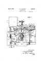
Fig. 1 is a plan view of a grading machine especially designed for handling small pieces such as heel lift segments;
Fig. 2 is a side elevation of the machine;
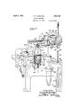
Fig. 3 is a vertical section on line 3-3 of Fig. 1; 1
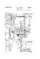
Figs. 4 and 5 are detail views in elevation illustrating the centering means for the-mov- Fig. 6 is a vertical cross section on line 66 of Fig. 2; and
Fig. 7 is a sectlon on line 77 of Fig. 6. The machme includes a pair of continuously driven detecting rolls 1 and 2 to which the blanks are fed one at a time under the gate 3. The gate 3 controls the usual detent pawl as hereinafter described. The lower edge of the gate 3 is beveled or inclined, as clearly shown inFigs. 2 and 3, so that as a blank is pushed forward toward the detect ing rolls under'gate 3, the latter will ride up on top of the blank. The shaft 4 of the upper detecting roll 1 is journaled in fixed bearing boxes 69 and is provided at one end outside of the machine frame with a worm wheel 5 which is continuously driven bya worm 6 fast on the armature shaft of a motor 7 secured to a bracket on one side of the machine frame. Shaft 4 also 'hasfixed thereon two gears 8, 8, meshing withtwo gears 9, 9, which are fast on shaft 10 of the lower detecting roll 2.
The crossbar 12 of the roll-supporting oke carries a pair of adjustable abutment screws 19 whose upper ends engage the under side of a pair of levers 20, 20, fixed to and projecting from a rock shaft 21 journaled on the frame of the machine, said levers being positioned one at each side of the middle of the yoke. When the roll 2 and yoke 12 is caused to tilt out of parallelism with roll 1 by an uneven blank, the higher of the two abutment screws 19 remains in engagement with its lever 20 and determines the adjustment of the grading means in accordance with the measurement of the thinner side of the blank as determined by roll 2. Rock shaft 21 also carries at one end, which projects outside the frame of the machine, a rearwardly extending lever arm 22 positioned beneath a stop abutment 23 attached to the machine frame, with provision for vertical adjustment, by means of a screw and slot connection 24, (Fig. 2).
Fastened to the under side of crossbar 12 of the yoke which supports the lower detecting roll 2 is a bracket 25 having an upstanding arm 26 in front of said lower detecting roll. Arm 26 is provided on its frontface with a guiding stud'27 which is normally seated within a guide in the form of a V- shaped notch or socket 28 formed on the under side of the table or bed-plate 29. The engagement of the stud 27 with the notch 28 limits the upward movement of the lower detecting roll'2 under the influence of springs 17 and 14, and when the roll 2, after separation from the roll 1, moves toward roll 1 the guiding stud 27 engages the walls of the V-shaped guiding notch 28 and positions the roll 2 longitudinally and properly centers it with relation to roll 1 so that the rolls will be in proper position to receive and measure the next blank. When the stud is in engagement with the notch the abutment stop 23 is so adjusted as to engage or approximately engage the arm 22.
As each blank is fed forward on top of table 29 between guides 30, 30, toward the detecting rolls it engages and lifts gate 3. Gate 3 is pivotedat 31 on the frame of the machine and is made with an upwardly extending arm 32 connected by a link33 with a detent pawl 34 pivotally mounted at 35 on the machine frame. A spring 36 connected at one end to arm 32 and at the other end to the machine frame yieldingly holds the gate 3 in its lowered'position (supplemented by gravity) and thereby holds the detent pawl 34 in engagement with a series of ratchet teeth 37 provided on ratchet wheel 38.
The free end of arm 22 engages the top side of a collar'39 fast on a vertical stem or rod 40 which carries at its upper end a rack slide 41 movable vertically between a guideblock 42 on the frame of the machine and a pinion 43, said rack slide 41 being made with rack or gear teeth 44 engaging the pinion 43. The pinion 43 is fast on a short hori zontal shaft 45 journaled in a bearin on the machine frame. Ratchet wheel 38 and a pointer 46 are also secured fast to shaft 45. The pointer 46 moves over an indicator scale 47 graduated to indicate irons and half irons displayed on a dial segment 48 concentric with shaft 45. This scale and pointer visually indicate the grade measurement of the blanks as determined by the detecting rolls in the same general manner as explained in said Nichols Patent No. 1,582,140.
The lower end of the vertical rod 40 ex.- tends through an aperture in arm 22 and has mounted upon it immediately above the arm 22 a coil spring 49 whose upper end bears against a fixed collar 50 and whose lower end bears against a loose collar or washer 51 seated on top of arm 22.
The up and down movement of the lower detecting roll 2 are transmitted to the lever arm 22 through the yoke bar 12 and the levers 20. Upward movement of the detecting roll 2 lifts levers 20 and consequently arm 22, and downward movement of the detecting roll 2 tends to depress arm 22 through spring 52 connected at its upper end to a crossbar 53 fast to the ends of levers 20, 20, and at its lower end to an angular post 54 projecting downward from the under side of crossbar 12.
A trip 55 is rigidly mounted on a rock shaft 56 above the detecting rolls and extends downward closely following the periphery of the roll 1 with its free end positioned close to the bite of the rolls on the delivery side thereof. Rock shaft 56 is journaled on the machine frame above roll 1 and has fixed thereto a short arm 57 which is connected by a link 58 to detent pawl 61. The rear end of link 58 is made with a slot 69 which engages a stud or pin 60 on the side of pawl 61. Pawl 61 is pivoted to the machine frame at 62. A spring 63 connecting the stud 60 and the link 58 tends yieldingly to urge the pawl 61 to the left (Fig. 3) and to hold the stud 60 is engagement with the lefthand end of slot 59. 'When the trip 55 occupies its normal position, as shown in the drawings, the stud 60 holds detent pawl 61 out of engagement with the, ratchet teeth 62 on ratchet wheel 38. It will be observed that the ratchet teeth 62 face in the opposite direction to the ratchet teeth 37. When trip 55 is swung to the right by a blank emerging from the detecting rolls, it acts through rock shaft 56,
- handed while the threaded connection between the other slide 64 and the shaft 67 is left-handed. Thus, when the shaft 67 is rotated by the hand wheel 68 in either direction,
the two slides 64 will be adjusted, simultaneously toward or from each other, thereby adjusting the spacing between the guides 30.
A shelf 71 is provided at the delivery side of the rolls 1 and 2 to receive the blanks as they are delivered from the rolls.
In operation, the blanks are fed in one by one over table 29 by hand (or it maybe by an automatic feeding mechanism such as that shown in'the Cogswell Patent No. 1,686,487 of October 2, 1928). As a blank is shoved under gate 3 the latter is raised thereby swinging arm 32 and link 33 to the left and disengaging detent pawl 34 from rack 37. The shaft'45 and pointer 46 are thus freed from restraint and tend toturn to the left to starting position under the influence of the usual spring, not shown. As soon as the blank entersbetween the rolls 1 and 2 the latter will be moved downwardly more or less depend ing upon the thickness of the blank and this movement will be transmitted through the yoke 11, 12, spring 52, levers 20, rock shaft 21, arm 22, vertical rod 40 and rack slide 41 to the pinion .43, thereby correspondingly adjusting the pointer 46. The adjustment of pointer 46 will, of course, not be preserved not be affected by thicker spots in the blank encountered by the detecting rolls, since thicker spots tend to move the pointer 46 to the right and the pointer shaft 45 is now locked against movement in that direction by The shaft 45 and pointer 46 will, however, be free to turn to the left in response to successively thinner spots encountered by the detecting rolls, since the gate 3 is still restingron top of the blank and the pawl 34 is therefore disengaged from its ratchet 37. As soon as the rear or trailing end of the blank passes out from under the gater3, the latter drops and causes pawl 34 to engage its ratchet thus locking the pointer shaft and pointer 46 against movement in either direction; The pointer willnow indicate on the scale 47 the thickness in irons of the thinnest spot inthe blank as deter,
mined by the detecting rolls. When the blank is-finally delivered from the detecting rolls and. falls onvtable 71 the tripx will return to normal position thus unlocking pawl 61 but the adjustment of'the pointer will not be disturbed since the pointer has a normal bias, as usual, toward zero position and is still held in its adjusted position by pawl 34.
The op'eratorhaving read the grade of theblank on the indicator may then remove it from table 71 and-distribute it into'its appropriatereceptacle, if the blanks are to be sorted according to grade, or otherwise disposed of it.
As soon as the next succeeding blank is fed.
Any upward movement of the detectingroll 2 and arm 22, while pawl 34 islocked to its ratchet, is taken up by spring'49, and any downward movement of the detectingroll 2 while pawl 61 is locked to its ratchet, is taken up by spring 52.
WVhen the blank passes between the detecting rolls and depresses roll 2, the stud 27 necessarily moves away from the V-shaped guide 28. from side to side the roll 2 instead of being moved downwardly in exact parallelism with the roll 1 is usually caused to tilt somewhat and may bethereby somewhat displaced ends wise. When the blank passes out from be tween. the detecting rolls and the'lower roll is again moved upwardly by its springs 14 and 17, the stud 27 enters the V-shaped notch 28 and by its engagement therewith centers or justifies the lower'detecting roll so that the two rolls will be intrue and accurate position for receiving and detecting the next blank entering the machine.
I claim: I
1. In a grading machine, a pair of. detecting rolls, one of which is movablebodily toward and from the other, a yoke upon which said movable roll is journaled, two springs one at each side of the middle of the yoke for yieldingly supporting the yoke and its roll so that each end thereof is independ' ently adjustable toward and from the other other roll in the direction of the pressure of the springs, a movable member against which said two springs are seated and a yielding support acting upon said member in opposition'to said two springs. V
2, In a grading machine, a pair of detecting rolls, one of which is movable bodily toward and from the other, a yoke upon which said movable roll 1s journaled, two springs one at each side of the middle of the yoke for yieldingly supporting the yoke As the blanks are usually uneven,-
ion
and its roll so that each end thereof is independently adjustable toward and from the other roll in the direction of the pressure of the springs, a lever against one arm of which said two springs are seated and a spring acting upon the other arm of said lever in opposition to said two springs.
3. In a grading machine, a pair of detecting rolls, one of which is movable bodily toward and from the other, a yoke upon which said movable roll is journaled, two springs one at each side of the middle of the yoke for yieldingly supporting the yoke and its roll so that each'end thereof is independently adjustable toward and from the other roll in the direction of the pressure of the springs, a lever, one arm of which is provided with a cross head against the ends of which said two springs are seated, and a spring acting upon the other arm of said lever in opposition to said two springs.
4. In a grading machine, detecting mechanism including a roll journaled in fixed bearings, a roll journaled in movablebearings permitting the ends of the roll to be independently adjusted toward and from the fixed roll and also permitting the adjustable roll to be shifted endwise with relation to the fixed roll, means yieldingly urging the adjustable roll toward the fixed roll and means operable by the movement of the endwise displaced adjustable roll toward the fixed roll for positioning the adjustable roll longitudinally with relation to the fixed roll.
5. In a grading machine, a pair of de tecting rolls one of which is journaled in fixed bearings, a yoke on which the other roll is journaled, said yoke and its roll being bodily adjustable toward and from the fixed roll, means for yieldingly urging said yoke and its roll toward the fixed roll, a guiding member projecting from the middle of said yoke and a fixed guiding member on the frame of the machine, said guiding members being adapted to engage when the yielding roll moves toward the fixed roll and to position and center said yoke and its roll longitudinally with relation to said fixed roll.
, 6. In a grading machine, a pair of detecting rolls one of which is journaled in fixed bearings, a yoke on which the other roll is journaled, said yoke and its roll being bodily adjustable toward and fromthe fixed roll, means for yieldingly urging said yoke and its roll toward the fixed roll, a guiding member projecting from the middle of said yoke and a fixed guiding member on the'frame of the machine, said guiding members being adapted to engage when the yielding roll moves toward the fixed roll and to position and center said yoke and its roll longitudinally with relation to said fixed roll, said guiding members also constituting a stop to limit the movement of said movable roll toward said fixed roll.
7. In a grading machine, a pair of detecting rolls one of which is journaled in fixed bearings, a yoke on which the other roll is journaled, said yoke and its roll being bodily adjustable toward and from the fixed roll, means for yieldingly urging said yoke and its roll toward the fixed roll, a guiding member projecting from the middle of said yoke and a fixed guiding member on the frame of the machine having a V-shaped notch adapted to cooperate with the guiding member on the yoke, said guiding members being adapted to engage when the yielding roll moves toward the fixed roll and to position and center said yoke and its roll longitudinally with relation to said fixed roll.
8. In a grading machine a pair of detecting rolls, a yoke on which one of said rolls is mounted, said yoke being bodily movable with its roll toward and from the other roll, means yieldingly pressing said yoke and its roll toward the other roll, grading means and mechanism for adjusting the grading means in response to movements of said yoke and its roll, said adjusting mechanism including a rock shaft, a lever arm fixed to said rock shaft and positively actuated by the yoke in one direction, a pair of levers fixed to said rock shaft and extending above said yoke whereby said yoke will positively move the lever arm upward, and a spring connecting said pair of levers to said yoke, whereby the yoke will move said lever arm yieldingly downward.
9. In a grading machine, a pair of detecting rolls, a yoke on which one of said rolls is mounted, said yoke being bodily movable with its roll toward and from the other roll, means yieldingly pressing said yoke and its roll toward the other roll, grading means and mechanism for adjusting the grading means in response to movements of said yoke and its roll, said adjusting mechanism including a rock shaft, a lever arm fixed to said rock shaft, a pair of other levers fixed to said rock shaft, one at each side of the middle of said yoke, adapted to be positively actuatedby the yoke in one direction, a crossbar connecting the free ends of said pair of levers, and a spring connecting said crossbar to said yoke for yieldingly actuating said pair of levers in the opposite direction.
10. In a grading machine, a pair of relatively movable detecting rolls, grading means, and adjusting mechanism for adjusting the grading means in response to movements of the detecting rolls, 'includin a normally disengaged ratchet and pawl for preserving in the grading means thinness measurements as determined by the detecting rolls, and a trip member pivoted at one end above the detecting rolls and extending downward and closely following the periphery of the upper roll with its free end and close to the bite of the JAMES W. JOHNSTON.
Priority Applications (1)
| Application Number | Priority Date | Filing Date | Title |
|---|---|---|---|
| US416427A US1852720A (en) | 1929-12-26 | 1929-12-26 | Grading machine |
Applications Claiming Priority (1)
| Application Number | Priority Date | Filing Date | Title |
|---|---|---|---|
| US416427A US1852720A (en) | 1929-12-26 | 1929-12-26 | Grading machine |
Publications (1)
| Publication Number | Publication Date |
|---|---|
| US1852720A true US1852720A (en) | 1932-04-05 |
Family
ID=23649933
Family Applications (1)
| Application Number | Title | Priority Date | Filing Date |
|---|---|---|---|
| US416427A Expired - Lifetime US1852720A (en) | 1929-12-26 | 1929-12-26 | Grading machine |
Country Status (1)
| Country | Link |
|---|---|
| US (1) | US1852720A (en) |
Cited By (1)
| Publication number | Priority date | Publication date | Assignee | Title |
|---|---|---|---|---|
| US2720101A (en) * | 1952-09-18 | 1955-10-11 | United Shoe Machinery Corp | Evening and grading machines |
-
1929
- 1929-12-26 US US416427A patent/US1852720A/en not_active Expired - Lifetime
Cited By (1)
| Publication number | Priority date | Publication date | Assignee | Title |
|---|---|---|---|---|
| US2720101A (en) * | 1952-09-18 | 1955-10-11 | United Shoe Machinery Corp | Evening and grading machines |
Similar Documents
| Publication | Publication Date | Title |
|---|---|---|
| US1852720A (en) | Grading machine | |
| US1686487A (en) | Grading machine | |
| US2093694A (en) | Grading machine | |
| US1130321A (en) | Machine for evening and grading cut soles and the like. | |
| US2315868A (en) | Grading machine | |
| US448586A (en) | Gage for sorting leather | |
| US2187204A (en) | Grading machine | |
| US2180591A (en) | Grading machine | |
| US1738818A (en) | Grading machine | |
| US1694408A (en) | Grading and distributing machine | |
| US1103520A (en) | Leather-marking machine. | |
| US2327283A (en) | Grading machine | |
| US1726610A (en) | Grading machine | |
| US1686694A (en) | Gauging machine | |
| US1945858A (en) | Grading machine | |
| US1829318A (en) | Fabric measuring apparatus and method | |
| US609667A (en) | eastwood | |
| US864861A (en) | Indicator-gage. | |
| US2008678A (en) | Cutting edge tester | |
| US1592295A (en) | Grading and marking machine | |
| US2146217A (en) | Grading machine | |
| US2272671A (en) | Grading machine | |
| US2360884A (en) | Grading machine | |
| US1703136A (en) | Evening and distributing machine | |
| US1703955A (en) | Grading machine |