US1852719A - Process and apparatus for forming molten glass - Google Patents
Process and apparatus for forming molten glass Download PDFInfo
- Publication number
- US1852719A US1852719A US347287A US34728729A US1852719A US 1852719 A US1852719 A US 1852719A US 347287 A US347287 A US 347287A US 34728729 A US34728729 A US 34728729A US 1852719 A US1852719 A US 1852719A
- Authority
- US
- United States
- Prior art keywords
- glass
- receiver
- ports
- bore
- column
- Prior art date
- Legal status (The legal status is an assumption and is not a legal conclusion. Google has not performed a legal analysis and makes no representation as to the accuracy of the status listed.)
- Expired - Lifetime
Links
- 238000000034 method Methods 0.000 title description 34
- 239000006060 molten glass Substances 0.000 title description 32
- 239000011521 glass Substances 0.000 description 123
- 230000005484 gravity Effects 0.000 description 17
- 230000001105 regulatory effect Effects 0.000 description 13
- 230000015572 biosynthetic process Effects 0.000 description 11
- 230000001276 controlling effect Effects 0.000 description 11
- 230000000694 effects Effects 0.000 description 6
- 239000000463 material Substances 0.000 description 6
- 230000000979 retarding effect Effects 0.000 description 5
- 239000000725 suspension Substances 0.000 description 4
- 238000007493 shaping process Methods 0.000 description 3
- 230000003111 delayed effect Effects 0.000 description 2
- 238000007599 discharging Methods 0.000 description 2
- 230000002706 hydrostatic effect Effects 0.000 description 2
- 239000002245 particle Substances 0.000 description 2
- 239000007787 solid Substances 0.000 description 2
- OKTJSMMVPCPJKN-UHFFFAOYSA-N Carbon Chemical compound [C] OKTJSMMVPCPJKN-UHFFFAOYSA-N 0.000 description 1
- 230000002238 attenuated effect Effects 0.000 description 1
- 239000012809 cooling fluid Substances 0.000 description 1
- 230000002939 deleterious effect Effects 0.000 description 1
- 238000000605 extraction Methods 0.000 description 1
- 239000012530 fluid Substances 0.000 description 1
- 238000007496 glass forming Methods 0.000 description 1
- 229910002804 graphite Inorganic materials 0.000 description 1
- 239000010439 graphite Substances 0.000 description 1
- VKYKSIONXSXAKP-UHFFFAOYSA-N hexamethylenetetramine Chemical compound C1N(C2)CN3CN1CN2C3 VKYKSIONXSXAKP-UHFFFAOYSA-N 0.000 description 1
- 238000004519 manufacturing process Methods 0.000 description 1
- 238000002844 melting Methods 0.000 description 1
- 230000008018 melting Effects 0.000 description 1
- 239000002184 metal Substances 0.000 description 1
- 229920000136 polysorbate Polymers 0.000 description 1
- 239000011148 porous material Substances 0.000 description 1
- 230000005855 radiation Effects 0.000 description 1
- 230000000284 resting effect Effects 0.000 description 1
- 230000000630 rising effect Effects 0.000 description 1
- 238000007665 sagging Methods 0.000 description 1
- 238000007789 sealing Methods 0.000 description 1
- 238000010008 shearing Methods 0.000 description 1
- 230000008961 swelling Effects 0.000 description 1
- XLYOFNOQVPJJNP-UHFFFAOYSA-N water Substances O XLYOFNOQVPJJNP-UHFFFAOYSA-N 0.000 description 1
Images
Classifications
-
- C—CHEMISTRY; METALLURGY
- C03—GLASS; MINERAL OR SLAG WOOL
- C03B—MANUFACTURE, SHAPING, OR SUPPLEMENTARY PROCESSES
- C03B7/00—Distributors for the molten glass; Means for taking-off charges of molten glass; Producing the gob, e.g. controlling the gob shape, weight or delivery tact
- C03B7/08—Feeder spouts, e.g. gob feeders
Definitions
- the process of controlling the discharge of molten glass is an improvement on the process wherein successive portions of a descending stream or column of molten glass are first brought into a more or less retarding or husbanding contact with surfaces, and are then suspended from or below such surfaces, the shaping imparted to the glass by Contact with said surfaces being thus modified and the filial shape of the glass being determined by the gravity stretch effective on the suspended port-ions of the glass.
- Such processes are applicable, inter alia, to mold charge formation, but may also be used for controlling the section of the column or of portions thereof.
- shape variations may be effected by varia tions in the time relation between the retarding or husbanding phase and the gravity stretch phase, and also by variations in the time relation between the shear cut and the 'f retarding or husbanding phase and/or the gravity stretch phase.
- This controlled variation in the frictional resistance which the contact surfaces offer to the surface of the molten glass may be in the time of its application, the location of its application. the effective area thereof, and /or its degree of such frictional resistance.
- the new and vimproved apparatus which also forms a part of my present invention provides means for performing my present procin the formation of mold charges, and the same may also be used in connection with other processes for forming the masses of glass.
- Fig. 1 is a view in vertical section showing the first phase in the cycle of production of a mold charge by the use of one form of apparatus that the invention may provide, the severing of the preceding charge having just occurred and the shears having not yet been opened or retracted out of the way, and Figs. 2 to 7, inclusive, illustrate succeeding phases in theprocess.
- 1 represents the submerged discharge outlet of a receptacle containing a supply of molten glass, such as a glass melting tank or a shallow extension of the same.
- E2 illustrates the column or stream of glass descending or flowing from the outlet 1.
- the descent of the glass may be in the form of a continuously flowing stream or the discharge may be intermittent or at a varied rate.
- FIG 3 represents an annular receiver which may be of any suitable form and material, as-metal or graphite.
- the receiver may be in one piece or partible.
- the receiver as of sub stantially cylindrical form, the body of the receiver being preferably internally chambered, as at 4, for the passage therethrough of a suitable cooling fluid, such, for instance, as water, which ma be admitted to the chamber or chambers an withdrawn therefrom 1n a manner well known inthe art.
- a suitable cooling fluid such as water
- the central opening or bore 5 of the receiver may be outwardly flared atits upper end, as
- I provide means for varying the friction between the glass andthe recelver wall.
- Small ports 10, 10a and 10b arranged in annular series, connect the manifolds 7, 7a and 7b, respectively, with the bore 5 ofthe receiver 4, said ports being of too small diameter to permit the entrance thereinto of the glass.
- I may use ports of substantially the size of the air holes which are provided in glass molds in which lettered ware is made to permit of the escape of air which would otherwise be entrapped in the letter-depressions in walls of the molds.
- the wall of the receiver at least between the manifold and the bore, may be of porous material so that the air will pass through the same either in the application of partial vacuum, atmospheric pressure or superatmospheric pressure.4
- 11 represents the shears which may be of any of the well-known types in common use in the glass industry, but preferably of the type which are advanced under the lower end of the bore to close and sever the glass and are retracted from such position as they open.
- the shears are arranged to cut in a plane beneath the receiver but spaced sufficiently below the lowerl end of the latter to prevent smearing or riveting of the sheared stub.
- FIG. 12 represents a pillow block which is mounted on an operating arm 13 and is arranged to be periodically positionedv at the lower end of the bore of the receiver 4 after the shears have severed a mold charge and have been retracted.
- the receiver 3 is preferably located close to the outlet 1 and is of such length relative to thev diameter of the;outlet that the lower end of a column ofglass, of suitable viscosity for the operation to be performed, issuing from the outlet will reach substantially to the lower end of the. bore 5 before the stream attenuates excessively.
- 'Ihe referred dimensions of a receiver suitable or an outlet of a given size may var according to viscosity of the lass, the rapi ity of the operations to be perfgormed and the character of the discharge of the glass through the outlet.
- the pillow block 12 is positioned at the lower end of the bore 5 of the receiver 4, preferably sealing the lower end of the receiver and supporting the glass which forms the lower end of the sheared stub so that the glass will ll out the rounded cavity 16 of the pillow block and the cross sectional area of the lower part of the bore of the receiver.
- the curve of the sides of the cavity of the pillow block should be tangent to the bore of the receiver and such as to mate and merge with the lower end of the receiver bore wit-hout a ⁇ corner or offset, thus preventing any pinching of the glass or the formation at the end of the pendant mass of glass of sharp corners which would chill unduly.
- the bore may if desired be made of constant diameter, but I prefer to make it of downwardly increasing diameter, at least as far as the lower ports l0, so that the adhesion of. the glass to the wall of the receiver or the frietional contact between the glass and the receiver will be under control and may be put into effect, regulated or relieved immediately in response to the changes in the fluid pressure applications at the ports.
- the pillow block 12 is removed, permitting the pendant glass to bag downwardly and stretch under the influence of gravity, as illustrated in Fig. 3.
- the partial vacuum in the lower ports 10 is relieved and replaced either by atmospheric pressure or by a slightly superatmospheric pressure, thus relieving the frictional contact of the glass with the wall of the lower portion of the bore of the receiver.
- Superatmospheric pressure may be required to prevent sticking.
- Partial vacuum is meanwhile caused in the ports 10a, thus holding the glass in frictional contact with the wall of the bore adjacent to the level of the ports 10a, either halting the movement of the adjacent glass or retarding its movement.
- the glass will show an increased tendency to bag downwardly, pulling out of contact with the wall of the lower portion of the bore adjacent to the ports 10.
- the natural tendency of the pendant mass of glass would be to form a ball or roughly rounded mass at its lower end, followed by an attenuated tail or neck, the point of the beginning of attenuation being at a fairly well defined point below the lowest point of contact of the glass with the receiver.
- I prevent such ball and tail or neck formation by a control which may include the simple expedient of changing vertically the position of the lowest point of contact between the glass and the wall of the receiver prior to the time such tendency to attenuate becomes excessive. This in e'ect will cause the pointat which the tendenc to attenuate becomes pronounced to s ift vertically, and by the suitable regulation of the time of varying this point I am enabled to accurately control the shape of the charge.
- the necessary formation of a chilled skin upon the glass by contact with thereceiver may be made use of as an aid to this control of a shape.
- the glass level will rise in contact with the wall of the bore above the upper ports 10b, as illustrated in Fig. 4, whereu on the subatmospheric pressure is relieve from the ports 10a and replaced with atmospheric pressure or superatmospheric pressure at sald ports, and partial vacuum is meanwhile appliedto the ports 10b, producing the status illustrated in Fig. wherein the glass is shown as held in frictional contact with the bore adjacent to the ports 10b, but released from such contact below said ports, thus permitting a further downwardly stretching of the pendant mass of glass.
- the partial vacuum inthe ports 10b may be suiicient to halt the movement of the glass or to merely retard such movement.
- sub-atmospheric pressure at ports 10 may occur immediately after the glass has iilled the bore up to the ports 10a and partial vacuum has been applied at the ports 10a.
- the release at ports 10 may take place when the glass level has risen to any point above the ports 10a and before it reaches the ports 10b.
- Such variations in the time of release at ports l() would cause a variation in time of stretching and also in the effect of such stretching.
- the release at ports 10 may be delayed until the glass level rises above ports 10b, the partial vacuum being applied at the latter ports, the ports 10a not operating to affeet the result.
- the operation would be a two-point Contact at ports 10 and sure, thus relieving the glass from frictional support by the bore of the receiver and causing the glass to further stretch -an attenuate
- the frictional resistance between the glass' and the wall of the orifice is diierent than the frictional resistance between the .particles of the glass itself.
- center of the section of downwardly flowing glass is of different temperature than the surrounding outer portions of side glass ⁇ owing to the more rapid extraction of heat from the latter by radiation and conduction to the normally cooler material of the orifice wall.
- shaping variations may be dictated by the regulation of the degree of frictional resistance through the control of the sub-atmospheric applications.
- Timing means for effecting such variations are of course well known in the art.
- the shape of the depending mass may be controlled within a relatively wide range, and that this range may be greatly enlarged by variation inthe periods within which partial vacuum is applied at the several series of ports and the 'relative timing of such apphcatlons.
- annular series of ports may be provided but the three series illustrated are considered suicient to ordinarily obtain satisfactory results.
- yI show the receiver provided with but one series of ports 100 connected at their inner ends to the manifold passage 7c which is adapted to be supplied with partial vacuum, atmospheric pressure and/or superatmospheric pressure by means of the port 8a and pipe 9a.
- the ports 100 are preferably located at a substantial distance above the lower end of the receiver bore.
- the pillow block 12a is shown provided with a linin inset 17 which is of material diliferm in eat conductivity from the material o the illow block-of greater or of less conductivity.
- the area, shape and thickness o f such lining may also vary. These variatlons in material, thickness, shape and areaalect the shape of the mold charge and partlcularly the contour of its lower end.
- Fig. 8 The first phase of the operation of the process is illustrated in Fig. 8, the mold charge last produced, shown at 18, having been severed by the closing of the shears 11 and the sheared stub resting on the shears.
- 'llbeypillow block is then removed and partial vacuum meanwhile applied to the ports 10c, thus, depending upon the degree of vacuum, either preventing the downward movement of the outer portions of the glass or merely retarding such movement to a greater or less degree as desired.
- the partial vacuum in the ports 10c is relieved and replaced by either atmosphericA pressure or superatmospheric pressure, thus releasing the mass of glass from its support and allowing it to stretch downwardly.
- the next phase is the closing of the shears to cut oil the mold charge depending below the outlet, as illustrated in Fig. 8.
- the bore 5 being downwardly enlarging
- the bore 5 be downwardly enlarging as far as ports 100 in order to free the glass from friction with the sides ofthe bore 5 when sub-atmospheric pressure in 10c is changed to atmospheric or superatmospheric pressure, but to avoid the inverted cone of glass descending entirely and causing the space beforementioned, it' is desirable that some frictional regiven to-the glass at or below the l'Qo. Below that it may be either straight or.l slightly downwardly contracting in order to cause the hydrostatic pressure to swell the glass at ports 10c and thus avoid a space developing between thel glass and the bore 5 at orts 10c.
- the process of forming a shaped mold charge from a descending column of molten glass which comprises controlling the movement of a portion of the column by alternate applications of sub-atmospheric pressure and a greater pressure to the lateral surface of the glass alternately to hinder such movement and to relieve sub-atmospheric pressure on the glass, and imparting the final shape to the mold charge by meansof the stretching action of gravity on thev glass while suspended.
- apparatus for formin mold charges from a descending column o molten glass
- the combination with a receptacle for the molten glass having a discharge outlet, of a receiver having a bore located below the outlet means for obtaining frictional contact between the glass and the wall of the receiver, means for varying the elevation of such contact relative to the bore of the receiver, and shears working below the receiver.
- the method of feeding molten glass in a mold charge of regulably controllable shape comprising the steps of discharging molten glass downwardly in a column from a downwardly opening discharge outlet into the bore of an open-ended annular receiver below and in alignment with said outlet, applying sub-atmospheric pressure through the inner walls of the receiver at different levels in the latter selectively to hinder the rate of downward sag of glass into suspension below the lower end of the receiver, relieving .such sub-atmospheric pressure after a predetermined period'of application thereof, and severing a mold charge from the glass in suspension below the receiver when such suspended glass has attained the shape desired.
- rlhe method of feeding molten glass in a mold charge of regulably controllable' shape comprising the steps of discharging glass downwardly in a column rom a downwardly opening outlet into the bore of an openended annular receiver below and in alignment with said outlet, temporarily supporting the lower end o said column adjacent to the lower end of the receiver to cause the lower end portion of said column to be enlarged sufciently to contact frictionally with the inner walls of the lower portion of the Y receiver, removing the' under-support, and controlling the rate of downward sag of glass from said column below the lower end of said receiver by applying sub-atmospheric pressure through the inner walls of the receiver to the glass therein at progressively higher levels in the receiver to cause progressively higher portions ofthe glass in the receiver to be brought into and maintained in frictional contact with the inner walls of the receiver, relieving such sub-atmospheric pressure at different levels in the receiver after predetermined periods of application thereof, lthereby aiding in controlling the shape of the downwardly sagging glass in suspension
- Apparatus for forming mold charges of regulably controlled shape comprising a receptacle for molten glass having a downwardly opening discharge outlet, an open ended annular receiverl disposed below and in alignment with said outlet, a removable bottom closure for the lower end of said rel DCver, said bottom closure being adapted to said outlet through the bore of said receiver to cause glass at the lower end of the column to pile up on the'bottom closure into frictional contact with the inner wall of the lower portion of said annular receiver, said annular receiver having means located at a plurality receptacle for molten glass having a downwardly opening discharge outlet, an openended annular receiver disposed below and in alignment with said outlet, a removable bottom closure for the lower end of said receiver, said bottom closure being adapted to support the lower end of a column of glass that has been discharged downwardly from said outlet through the bore of said receiver to cause glass at the lower end of the column to pile up on the bottom closure into :Erictional contact with the inner wall ofthe lower portion of said annular receiver,
- Apparatus for forming mold charges of regulably controlled shape comprising a
Landscapes
- Chemical & Material Sciences (AREA)
- Engineering & Computer Science (AREA)
- Materials Engineering (AREA)
- Organic Chemistry (AREA)
- Re-Forming, After-Treatment, Cutting And Transporting Of Glass Products (AREA)
Description
April 5, 1932- G. E. HOWARD 1,852,719
PROCESS AND APPARATUS FOR FORMING MOLTEN GLASS Filed March l5, 1929. 2 Sheets-Sheet l Inventor Mzzess: @602:96 (g/@ward ya/9W @ym *ya I,
April s, 1932. G. E HOWARD 1,852,719
PROCESS AND APPARATUS FOR FORMING MOLTEN GLASS Filed March 15, 1929 2 Sheets-Sheet 2 I [nu en 014 Mness." l l Geozfge 21B/award Ht tornec'y Patented Apr. 5, 1932 UNITED STATES PATENT OFFICE GEORGE E. HOWARD, OF BUTLER, PENNSYLVANIA, ASSIGNOR T HARTFORD-EMPIRE COMPANY, OF HARTFORD, CONNECTICUT, A. CORPORATION OF DELAWARE Application led. March 15, 1929. Serial No. 347,287.
The process of controlling the discharge of molten glass, which forms part of the subject matter of the present invention, is an improvement on the process wherein successive portions of a descending stream or column of molten glass are first brought into a more or less retarding or husbanding contact with surfaces, and are then suspended from or below such surfaces, the shaping imparted to the glass by Contact with said surfaces being thus modified and the filial shape of the glass being determined by the gravity stretch effective on the suspended port-ions of the glass.
Such processes are applicable, inter alia, to mold charge formation, but may also be used for controlling the section of the column or of portions thereof.
In processes of this general character, shape variations may be effected by varia tions in the time relation between the retarding or husbanding phase and the gravity stretch phase, and also by variations in the time relation between the shear cut and the 'f retarding or husbanding phase and/or the gravity stretch phase.
In the process which forms part of the subject of the present application I greatly increase the range of shape variation by employing a variable control of the frictional resistance between the contact surfaces and the surface of the molten glass.
This controlled variation in the frictional resistance which the contact surfaces offer to the surface of the molten glass may be in the time of its application, the location of its application. the effective area thereof, and /or its degree of such frictional resistance.
By the use of my controlled variable frictional resistance in the practice of the process hereinafter described, I am enabled, to some extent, to control the character and extent of formation of chilled skin upon the glass which ultimately forms the mold charge. I'Vhile a skin upon the outer portion of the glass will be created because of contact of the glass with the instrumentalities used, I avoid or minimize to a large extent any deleterious effects of this skin formation, first by 50 avoiding undue attenuation of the glass and thus maintaining a relatively large hot interior portion thereof and second by providing a reheatfng period during which all portions of the glass forming the charge are out of contact with any chilling instrumentalities. Y
Other features of novelty in my present process will appear from the following d'escription.
. The new and vimproved apparatus which also forms a part of my present invention provides means for performing my present procin the formation of mold charges, and the same may also be used in connection with other processes for forming the masses of glass.
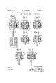
In the accompanying drawings wherein I have illustrated the working of my new and improved process for the purpose of forming mold charges in connection with my new and improved apparatus, Fig. 1 is a view in vertical section showing the first phase in the cycle of production of a mold charge by the use of one form of apparatus that the invention may provide, the severing of the preceding charge having just occurred and the shears having not yet been opened or retracted out of the way, and Figs. 2 to 7, inclusive, illustrate succeeding phases in theprocess.
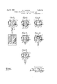
Figs. 8 to 13, inclusive,.-illustrate phases of the process worked in co'imection with a somewhat different form of apparatus.
Referring first to Figs. l to 7, inclusive, 1 represents the submerged discharge outlet of a receptacle containing a supply of molten glass, such as a glass melting tank or a shallow extension of the same.
E2, illustrates the column or stream of glass descending or flowing from the outlet 1.
The descent of the glass may be in the form of a continuously flowing stream or the discharge may be intermittent or at a varied rate.
3 represents an annular receiver which may be of any suitable form and material, as-metal or graphite. The receiver may be in one piece or partible.
I have illustrated the receiver as of sub stantially cylindrical form, the body of the receiver being preferably internally chambered, as at 4, for the passage therethrough of a suitable cooling fluid, such, for instance, as water, which ma be admitted to the chamber or chambers an withdrawn therefrom 1n a manner well known inthe art.`
The central opening or bore 5 of the receiver may be outwardly flared atits upper end, as
at 6, tov better receive the downwardly moving lieving and Varying the frictional contact bel tween the wall of the receiver andthe surface of the glass.
For this purpose I provide means for varying the friction between the glass andthe recelver wall.
Thus at different levels ofthe receiver, such as adjacent to the lower end of the latter,`in termediate of the latter, and adjacent t0 the upper end thereof, I provide annular manifold passages, 7, 7a, and 7 respectively, each of which is adapted to be connected, as.by a port 8 and a pipe 9, to a controlled supply of sub-atmospheric pressure and atmospheric pressure and/or superatmospheric pressure,A
such as is found in modern glass factories.
However, the wall of the receiver, at least between the manifold and the bore, may be of porous material so that the air will pass through the same either in the application of partial vacuum, atmospheric pressure or superatmospheric pressure.4
11 represents the shears which may be of any of the well-known types in common use in the glass industry, but preferably of the type which are advanced under the lower end of the bore to close and sever the glass and are retracted from such position as they open.
The shears are arranged to cut in a plane beneath the receiver but spaced sufficiently below the lowerl end of the latter to prevent smearing or riveting of the sheared stub.
12, (see Fig. 2), represents a pillow block which is mounted on an operating arm 13 and is arranged to be periodically positionedv at the lower end of the bore of the receiver 4 after the shears have severed a mold charge and have been retracted.
The receiver 3 is preferably located close to the outlet 1 and is of such length relative to thev diameter of the;outlet that the lower end of a column ofglass, of suitable viscosity for the operation to be performed, issuing from the outlet will reach substantially to the lower end of the. bore 5 before the stream attenuates excessively. 'Ihe referred dimensions of a receiver suitable or an outlet of a given size may var according to viscosity of the lass, the rapi ity of the operations to be perfgormed and the character of the discharge of the glass through the outlet. In the case of fairly hot glass, which is preferably used in the practice of my method, flowing in a steady constant stream from the outlet, 1t is preferable that the lower end of the receiver be not removed from the outlet 1 a distance more than two and one-half times the diameter of the outlet. The foregoing statements of the preferred relative dimensions of the parts are not to be taken as limitations, as my apparatus and method are useful in the feeding of frlass when these dimensions are not observed but are stated as dimensions which are believed to give the best results in making high quality glassware.
M improved process as illustrated by Figs. 1 to l, inclusive, is as follows:
Assuming the status illustrated in Fig. l wherein the shears have just closed and severed the mold charge'last produced vand shownat 15 in Fig. 1 as dropping down toward the waiting mold or other container, the sheared stub is partially supported by the closed shears.
Referring next to Fig. 2, as the shears open and are withdrawn to their retracted position, the pillow block 12 is positioned at the lower end of the bore 5 of the receiver 4, preferably sealing the lower end of the receiver and supporting the glass which forms the lower end of the sheared stub so that the glass will ll out the rounded cavity 16 of the pillow block and the cross sectional area of the lower part of the bore of the receiver.
The curve of the sides of the cavity of the pillow block should be tangent to the bore of the receiver and such as to mate and merge with the lower end of the receiver bore wit-hout a` corner or offset, thus preventing any pinching of the glass or the formation at the end of the pendant mass of glass of sharp corners which would chill unduly.
As the glass accumulates in the bore 5, the level of the same in contact with the wall of the bore will rise above the level of the ports 10 and sub-atmospheric pressure is applied to said ports, thusv tending to hold the adjacent glass in frictional contact with the wall of the bore, so as to hinder, that is either halt or retard such movement, depending upon the degree of vacuum used.
The bore may if desired be made of constant diameter, but I prefer to make it of downwardly increasing diameter, at least as far as the lower ports l0, so that the adhesion of. the glass to the wall of the receiver or the frietional contact between the glass and the receiver will be under control and may be put into effect, regulated or relieved immediately in response to the changes in the fluid pressure applications at the ports.
After the glass has been brought into frictional contact with the wall of the bore, adjacent to the ports 10, the pillow block 12 is removed, permitting the pendant glass to bag downwardly and stretch under the influence of gravity, as illustrated in Fig. 3.
Meanwhile, owing to the fact that the low otglass from the outlet l exceeds the amount of glass leaving the bore 5 below the ports 10, the level of glass filling the full cross sectional area of the receiver bore will ascend, preferably eventually rising above the intermediate ports 10a, as illustrated in Fig. 3.
It is evident that glass will iiow down the interior of the mass of glass, filling out and downwardly stretching the inelosing skin of the mass which depends below the receiver, but at this stage the input of glass in the receiver will exceed the flow of glass out of the receiver.
When the level of glass in contact with the wall of the receiver rises above the intermediate port 10a, the partial vacuum in the lower ports 10 is relieved and replaced either by atmospheric pressure or by a slightly superatmospheric pressure, thus relieving the frictional contact of the glass with the wall of the lower portion of the bore of the receiver. Superatmospheric pressure may be required to prevent sticking.
Partial vacuum is meanwhile caused in the ports 10a, thus holding the glass in frictional contact with the wall of the bore adjacent to the level of the ports 10a, either halting the movement of the adjacent glass or retarding its movement.
As illustrated in Fig. 4 the glass will show an increased tendency to bag downwardly, pulling out of contact with the wall of the lower portion of the bore adjacent to the ports 10.
The natural tendency of the pendant mass of glass would be to form a ball or roughly rounded mass at its lower end, followed by an attenuated tail or neck, the point of the beginning of attenuation being at a fairly well defined point below the lowest point of contact of the glass with the receiver. I prevent such ball and tail or neck formation by a control which may include the simple expedient of changing vertically the position of the lowest point of contact between the glass and the wall of the receiver prior to the time such tendency to attenuate becomes excessive. This in e'ect will cause the pointat which the tendenc to attenuate becomes pronounced to s ift vertically, and by the suitable regulation of the time of varying this point I am enabled to accurately control the shape of the charge. The necessary formation of a chilled skin upon the glass by contact with thereceiver may be made use of as an aid to this control of a shape.
As the glass accumulates in the receiver above the level of the ports 10a, due to the frictional contact with the wall of the bore in which the glass is held by the partial vacuum applied at said ports, the glass level will rise in contact with the wall of the bore above the upper ports 10b, as illustrated in Fig. 4, whereu on the subatmospheric pressure is relieve from the ports 10a and replaced with atmospheric pressure or superatmospheric pressure at sald ports, and partial vacuum is meanwhile appliedto the ports 10b, producing the status illustrated in Fig. wherein the glass is shown as held in frictional contact with the bore adjacent to the ports 10b, but released from such contact below said ports, thus permitting a further downwardly stretching of the pendant mass of glass. The partial vacuum inthe ports 10b may be suiicient to halt the movement of the glass or to merely retard such movement.
It is evident that the release of sub-atmospheric pressure at ports 10, for example, may occur immediately after the glass has iilled the bore up to the ports 10a and partial vacuum has been applied at the ports 10a. The release at ports 10 may take place when the glass level has risen to any point above the ports 10a and before it reaches the ports 10b. Such variations in the time of release at ports l() would cause a variation in time of stretching and also in the effect of such stretching.
Again the release of partial vacuum at ports 10 may be delayed until the glass level rises to a point above ports 10b, and its release at ports 10 and 10a may occur at very close intervals, thus causing still other changes in the iinal shape.
Again the release at ports 10 may be delayed until the glass level rises above ports 10b, the partial vacuum being applied at the latter ports, the ports 10a not operating to affeet the result. In this case the operation would be a two-point Contact at ports 10 and sure, thus relieving the glass from frictional support by the bore of the receiver and causing the glass to further stretch -an attenuate The frictional resistance between the glass' and the wall of the orifice is diierent than the frictional resistance between the .particles of the glass itself. f
Also the center of the section of downwardly flowing glass is of different temperature than the surrounding outer portions of side glass `owing to the more rapid extraction of heat from the latter by radiation and conduction to the normally cooler material of the orifice wall.
Consequently in a stable vcondition this difference of friction is constant, not subject to control, and a certain shape will be assumed by the pendant glass, Such shape will be constant and is determined by the physical lawsgoverning the characteristics of molten glass.-
Moreover shaping variations may be efected by the regulation of the degree of frictional resistance through the control of the sub-atmospheric applications.
Again by controllably varying the time during which the stub 1s supported by thek shears after severance, further variations 1n shape may) be obtained.
Again y varying the time interval between the opening of the shears and the positioning of the pillow block at the lower end of the receiver further-variations of shape may be effected.
Again by variations in the time of pillow block removal relative to the closing of the shears, and, again relative to the opening of the shears, further shape variations may be effected.
Timing means for effecting such variations are of course well known in the art.
It is evident that by regulating and varying the time relation between the phases wherein successive portions of the glass are held or retarded in frictional contact with the wall of the receiver bore and wherein they are allowed to hang subject to the influence of gravity, the shape of the depending mass may be controlled within a relatively wide range, and that this range may be greatly enlarged by variation inthe periods within which partial vacuum is applied at the several series of ports and the 'relative timing of such apphcatlons.
Any number of annular series of ports may be provided but the three series illustrated are considered suicient to ordinarily obtain satisfactory results.
It is of course not necessary to entirely halt the movement of the surfaces of the glass in frictional contact with the wall of the bore, but the'application of partial vacuum ma be employed to retard instead of entirely alt the movement of the exterior portions of the glass and the degree of such retardation may also e used for the control of the shaping of the mold charges.
Referring now to Figs. 8 to 13, inclusive,
yI show the receiver provided with but one series of ports 100 connected at their inner ends to the manifold passage 7c which is adapted to be supplied with partial vacuum, atmospheric pressure and/or superatmospheric pressure by means of the port 8a and pipe 9a.
The ports 100 are preferably located at a substantial distance above the lower end of the receiver bore.
The pillow block 12a is shown provided with a linin inset 17 which is of material diliferm in eat conductivity from the material o the illow block-of greater or of less conductivity. The area, shape and thickness o f such lining may also vary. These variatlons in material, thickness, shape and areaalect the shape of the mold charge and partlcularly the contour of its lower end.
The first phase of the operation of the process is illustrated in Fig. 8, the mold charge last produced, shown at 18, having been severed by the closing of the shears 11 and the sheared stub resting on the shears.
In the next phase, illustrated in Fig. 9, the shears have been retracted and thepillow block 12a positioned below the outlet, causing .the lower end of the stub to swell out"and ll the full cross-sectional area of the bore of. the receiver to a point above the ports 100. I
'llbeypillow block is then removed and partial vacuum meanwhile applied to the ports 10c, thus, depending upon the degree of vacuum, either preventing the downward movement of the outer portions of the glass or merely retarding such movement to a greater or less degree as desired.
The result is the next phase, illustrated in Fig. 10, wherein the lower portion of the glass gradually bags downwardly, this downward bagging continuing, as shown in Figs. 11 and 12, and the glass flowing down through the interior of the mass of glass and filling out the enclosing skin.
In the next phase, illustrated in Fig. 13, the partial vacuum in the ports 10c is relieved and replaced by either atmosphericA pressure or superatmospheric pressure, thus releasing the mass of glass from its support and allowing it to stretch downwardly.
The next phase is the closing of the shears to cut oil the mold charge depending below the outlet, as illustrated in Fig. 8.
It is evident that a wide range in variations of shape may be obtained by varying the time relation between the phases wherein the outer portions of successive portions of the glass are supported either with an entire cessation of movement or with a greater or less retardation of movement and are subjected to the stretching intiuence of gravity Another manner in which my process may be worked in connection with this apparatus is by employing alternate applications of partial vacuum and atmospheric pressure or superatmospheric pressure to the surfaces of the glass through the ports 100, varying the time intervals between vacuum and atmospheric pressure applications, or vacuum and superatmospheric applications, thus regulating and vari ably controlling the movement of the outer portions of the glass relative to the movement of the interior portions of the mass.
It-is evident that by this means a considerable range of mold charge shapes may be produced, with conditions of temperature, etc., remaining constant.
The bore 5 being downwardly enlarging,
l it is evident that upon release of subatmospheric pressure the mass of glass in the bore 5 is free to descend without any frictional resistance with the sides of the bore. With even a small descent, a space will develop between the glass and the wall of the bore.
Contact with the bore by the glass could then not be resstablished unless the air in the space thus developed could be exhausted and in addition the glass could swell out to meet the wall of the bore.
Owing to the limited size of the port openings 10o, such exhaustion of air would not be possible .for even a very minute space so developed between the glass and the bore.
Also every particle in 'the charge would tend to descend with equal speed in accordance with the law of gravity.
If, however, frictional resistance is applied to the mass of glass below the ports 10o, for instance, then the glass in the bore will not descend freely but the head of glass will exert a swelling tendency due to hydrostatic pressure.l
It may be desirable, therefore, that the bore 5 be downwardly enlarging as far as ports 100 in order to free the glass from friction with the sides ofthe bore 5 when sub-atmospheric pressure in 10c is changed to atmospheric or superatmospheric pressure, but to avoid the inverted cone of glass descending entirely and causing the space beforementioned, it' is desirable that some frictional regiven to-the glass at or below the l'Qo. Below that it may be either straight or.l slightly downwardly contracting in order to cause the hydrostatic pressure to swell the glass at ports 10c and thus avoid a space developing between thel glass and the bore 5 at orts 10c. A
hile, for the purpose of more clearly i1- lustrating the principles of my invention, I have illustrated and described my process and apparatus as used for mold charge formation, it is obvious that either the process or apparatus or both may be employed'for variably controlling the characteristics of a tubular or solid descending column or mass of molten glass and especially as to its cross sectional size and shape. V
What I desire to claim is 1. The process of controlling the shape of a descending solid mass of molten glass which comprises hindering the movement of the glass by controlled frictional resistance, and varying such shape by regulating such frictional resistance.
2. The process of controlling the shape of a descending mass of molten glass which comprises hindering the movement of the mass by frictional resistance effective on the lateral surface of the mass, imparting the final shape to the mass by means of the stretching action of gravity on the glass while suspended, and regulating such shape by varying the frictional resistance.
3. The process of controlling the shape of a descending mass of molten glass which comprises hindering themovement of the mass I by frictional resistance effective on -the lateral surface of the mass, imparting the final ed, and regulating the shape by varying the gravity stretch phase.
4. The process of forming a shaped mold charge from a descending column of molten glass which comprises hindering the movement of a portion of the column by means of partial vacuum applied to its lateral surface, and imparting the final shape to the mold charge by means of the stretching action of gravity on the glass while suspended.
5. The process of forming a shaped mold charge from a descending column of molten glass which comprises controlling the movement of a portion of the column by alternate applications of sub-atmospheric pressure and a greater pressure to the lateral surface of the glass alternately to hinder such movement and to relieve sub-atmospheric pressure on the glass, and imparting the final shape to the mold charge by meansof the stretching action of gravity on thev glass while suspended.
6. The process of forming a shaped mold charge from a descending column of molten glass, which comprises hindering the movement of a portion of the column by mea-ns of frictional contact of the lateral surface of the column, imparting the final shape to the mold charge by means of the stretching action of gravity on the glass while suspended, and regulating said shape by varying the duration of application of such frictional contact.
7. The process of forming a shaped mold charge from a descending column of molten glass which comprises hindering the movement of a portion of the column by means of frictional contact of the lateral surface ofthe column, imparting the final shape to the mold charge by means of the stretching action of gravity on the glass while suspended, and regulating said shape by varying the intensity of such frictional contact.
8. The process of forming a mold charge from a descending column of molten glass which comprises hindering the movement of a port-ion of the column by frictional contact with a surface, regulating the skin formation on said glass by varying the area of such contact, and imparting the final shape to the inold charge by means of the stretching effect of gravity on the mass of glass while suspended.
9. The process of forming a mold charge from a descending column of molten glass which comprises hindering the movement of a portion of the column by frictional contact with a surface, regulating the skin formation on said glass by varying the intensity of such contact, and imparting the final shape to the mold charge by means of the stretching effect of gravity on .the mass of glass while suspended. Y
10. The process of forming a mold charge from a descending column of molten glass which comprises hindering the movement of a portion of the column by frictional contact with a surface, regulating the skin formation on said glass by varying the duration of such contact, and imparting the final shape to the mold charge by means of the stretching efl'ect of gravity on the mass of glass while suspended.
11. The process of forming a mold charge from a descending column of molten Vglass which comprises hindering the movement of a portion of the column by frictional contact with a surface, regulating such contact by varying the elevation thereof, and imparting the final shape to the mold charge by means of the stretching effect of gravity on the mass of glass while suspended. l
12. The process of forming a mold charge from a. descending column of .molten glass which comprises hindering the movement of a portion of the column by frictional contact with a surface, regulating such contact b varying the time and the elevation thereo and imparting the final shape to the mold charge by means of the stretching effect of gravit on the mass of glass while suspended. 13. In apparatus for forming shaped mold charges from a descending column of molten glass, the combination with a receptacle for the molten glass having adischarge outlet,
of a receiver having a bore located below said outlet, pneumatic means for obtaining frictional contact between the internal wall of said receiver and the glass to hinder the movement of the glass through the receiver, and shears working below said receiver.
15. In apparatus for formin mold charges from a descending column o molten glass, the combination with a receptacle for the molten glass having a discharge outlet, of a receiver having a bore located below the outlet, means for obtaining frictional contact between the glass and the wall of the receiver, means for varying the elevation of such contact relative to the bore of the receiver, and shears working below the receiver. 16. In apparatus for forming shaped mold charges from a descending column of molten glass, the combination with a receptacle for the molten glass having a discharge outlet, of a receiver having a bore located below said outlet, shears to cut the glass working below the receiver, and a closure arranged to be positioned below the receiver to support the sheared stub after the shearing operation, said closure having the central portion of its contact surface of material of different heatconductivity than the remainder of such contact surface.
17. The method of feeding molten glass in a mold charge of regulably controllable shape, comprising the steps of discharging molten glass downwardly in a column from a downwardly opening discharge outlet into the bore of an open-ended annular receiver below and in alignment with said outlet, applying sub-atmospheric pressure through the inner walls of the receiver at different levels in the latter selectively to hinder the rate of downward sag of glass into suspension below the lower end of the receiver, relieving .such sub-atmospheric pressure after a predetermined period'of application thereof, and severing a mold charge from the glass in suspension below the receiver when such suspended glass has attained the shape desired.
18. rlhe method of feeding molten glass in a mold charge of regulably controllable' shape, comprising the steps of discharging glass downwardly in a column rom a downwardly opening outlet into the bore of an openended annular receiver below and in alignment with said outlet, temporarily supporting the lower end o said column adjacent to the lower end of the receiver to cause the lower end portion of said column to be enlarged sufciently to contact frictionally with the inner walls of the lower portion of the Y receiver, removing the' under-support, and controlling the rate of downward sag of glass from said column below the lower end of said receiver by applying sub-atmospheric pressure through the inner walls of the receiver to the glass therein at progressively higher levels in the receiver to cause progressively higher portions ofthe glass in the receiver to be brought into and maintained in frictional contact with the inner walls of the receiver, relieving such sub-atmospheric pressure at different levels in the receiver after predetermined periods of application thereof, lthereby aiding in controlling the shape of the downwardly sagging glass in suspension below the receiver, and severing a mold charge from the suspended glass below the receiver when such suspended glass has attained the desired shape.
19. Apparatus for forming mold charges of regulably controlled shape, comprising a receptacle for molten glass having a downwardly opening discharge outlet, an open ended annular receiverl disposed below and in alignment with said outlet, a removable bottom closure for the lower end of said rel ceiver, said bottom closure being adapted to said outlet through the bore of said receiver to cause glass at the lower end of the column to pile up on the'bottom closure into frictional contact with the inner wall of the lower portion of said annular receiver, said annular receiver having means located at a plurality receptacle for molten glass having a downwardly opening discharge outlet, an openended annular receiver disposed below and in alignment with said outlet, a removable bottom closure for the lower end of said receiver, said bottom closure being adapted to support the lower end of a column of glass that has been discharged downwardly from said outlet through the bore of said receiver to cause glass at the lower end of the column to pile up on the bottom closure into :Erictional contact with the inner wall ofthe lower portion of said annular receiver, said annular receiver having means located at a plurality of different levels for applying sub-atmospheric pressure to different portions of the glass column in said receiver to.cause rictional contact Aof such portions of the glass column with the adjacent portions of the bore of the receiver and thereby to aid in controlling the shape of the glassin suspension below the receiver when said bottom closure'has been removed, said receiver also having means for relieving the sub-atmospheric pressure at any of said levels in the receiver after a predetermined period of application of such sub- January, 1929.
GEORGE E. HOWARD.
'support the lower end of'a column of glass that has been' discharged downwardly from vno below the receiver when such suspended glass v has attained the desired shape.
20. Apparatus for forming mold charges of regulably controlled shape, comprising a
Priority Applications (1)
| Application Number | Priority Date | Filing Date | Title |
|---|---|---|---|
| US347287A US1852719A (en) | 1929-03-15 | 1929-03-15 | Process and apparatus for forming molten glass |
Applications Claiming Priority (1)
| Application Number | Priority Date | Filing Date | Title |
|---|---|---|---|
| US347287A US1852719A (en) | 1929-03-15 | 1929-03-15 | Process and apparatus for forming molten glass |
Publications (1)
| Publication Number | Publication Date |
|---|---|
| US1852719A true US1852719A (en) | 1932-04-05 |
Family
ID=23363098
Family Applications (1)
| Application Number | Title | Priority Date | Filing Date |
|---|---|---|---|
| US347287A Expired - Lifetime US1852719A (en) | 1929-03-15 | 1929-03-15 | Process and apparatus for forming molten glass |
Country Status (1)
| Country | Link |
|---|---|
| US (1) | US1852719A (en) |
-
1929
- 1929-03-15 US US347287A patent/US1852719A/en not_active Expired - Lifetime
Similar Documents
| Publication | Publication Date | Title |
|---|---|---|
| US2688823A (en) | Method and apparatus for forming glass parisons | |
| US2310715A (en) | Method of and apparatus for feeding glass | |
| US1852719A (en) | Process and apparatus for forming molten glass | |
| US1892765A (en) | Method and apparatus for feeding molten glass | |
| US2128249A (en) | Apparatus for and method of feeding molten glass | |
| US1739519A (en) | Feeding molten glass | |
| US2485807A (en) | Means for controlling the temperature of glass in plural orifices of glass feeders | |
| US1415824A (en) | Method of treating and working glass | |
| US1902140A (en) | Manufacture of hollow glassware | |
| US2951316A (en) | Process for molding massive bodies of glass having high strength | |
| US1608601A (en) | Apparatus fob | |
| US1961015A (en) | Method of and apparatus for feeding glass | |
| US1763968A (en) | Method of delivering and shaping molten glass | |
| US1853003A (en) | Process and apparatus for producing shaped mold charges of molten glass | |
| US2596042A (en) | Slow speed glass feeder | |
| CN211255679U (en) | Process glass multi-bubble forming device | |
| US2050205A (en) | Means for and method of preventing issuance of refractory-contaminated glass from feeder outlets | |
| US1853002A (en) | Method of feeding molten glass | |
| US2012583A (en) | Method of manufacturing bottles and similar articles of hollow glassware | |
| US3130028A (en) | Glass feeding | |
| US1620207A (en) | Method and apparatus for feeding molten glass | |
| US1905468A (en) | Process and apparatus for forming shaped mold charges of molten glass | |
| US1798217A (en) | Method of and apparatus for forming glass articles | |
| US2003058A (en) | Glass feeder | |
| US1631107A (en) | Feeding molten glass |