US1852716A - Gas lift manifold - Google Patents
Gas lift manifold Download PDFInfo
- Publication number
- US1852716A US1852716A US480327A US48032730A US1852716A US 1852716 A US1852716 A US 1852716A US 480327 A US480327 A US 480327A US 48032730 A US48032730 A US 48032730A US 1852716 A US1852716 A US 1852716A
- Authority
- US
- United States
- Prior art keywords
- tubing
- gas
- valve
- well
- stem
- Prior art date
- Legal status (The legal status is an assumption and is not a legal conclusion. Google has not performed a legal analysis and makes no representation as to the accuracy of the status listed.)
- Expired - Lifetime
Links
- 238000012856 packing Methods 0.000 description 33
- 230000008878 coupling Effects 0.000 description 24
- 238000010168 coupling process Methods 0.000 description 24
- 238000005859 coupling reaction Methods 0.000 description 24
- 238000000034 method Methods 0.000 description 22
- 239000012530 fluid Substances 0.000 description 17
- 230000008093 supporting effect Effects 0.000 description 4
- SRVJKTDHMYAMHA-WUXMJOGZSA-N thioacetazone Chemical compound CC(=O)NC1=CC=C(\C=N\NC(N)=S)C=C1 SRVJKTDHMYAMHA-WUXMJOGZSA-N 0.000 description 3
- 244000273618 Sphenoclea zeylanica Species 0.000 description 2
- 230000015572 biosynthetic process Effects 0.000 description 2
- 238000010276 construction Methods 0.000 description 2
- 238000004519 manufacturing process Methods 0.000 description 2
- 241001203952 Feia Species 0.000 description 1
- 244000182067 Fraxinus ornus Species 0.000 description 1
- 102100027256 Melanoma-associated antigen H1 Human genes 0.000 description 1
- 208000036366 Sensation of pressure Diseases 0.000 description 1
- 239000003795 chemical substances by application Substances 0.000 description 1
- 108010038764 cytoplasmic linker protein 170 Proteins 0.000 description 1
- 230000000694 effects Effects 0.000 description 1
- 208000023414 familial retinal arterial macroaneurysm Diseases 0.000 description 1
- 230000001771 impaired effect Effects 0.000 description 1
- 238000012423 maintenance Methods 0.000 description 1
- 239000000463 material Substances 0.000 description 1
- 239000003129 oil well Substances 0.000 description 1
- 239000007787 solid Substances 0.000 description 1
- 239000000725 suspension Substances 0.000 description 1
Images


Classifications
-
- E—FIXED CONSTRUCTIONS
- E21—EARTH OR ROCK DRILLING; MINING
- E21B—EARTH OR ROCK DRILLING; OBTAINING OIL, GAS, WATER, SOLUBLE OR MELTABLE MATERIALS OR A SLURRY OF MINERALS FROM WELLS
- E21B33/00—Sealing or packing boreholes or wells
- E21B33/02—Surface sealing or packing
- E21B33/03—Well heads; Setting-up thereof
- E21B33/068—Well heads; Setting-up thereof having provision for introducing objects or fluids into, or removing objects from, wells
Definitions
- This invention relates to devices for lowering tubing in oil wells and especially in wells which are being flowed by the well known gas-lift metho
- the principal object of the invention is to provide a method and a structurewhereby the tubing may be lowered in a gas-lift well toa lower level durin and simultaneously with introduction of the high pressure gas which is being employed to flow the well.
- the invention resides in a method and in a means whereby the circulation of high pressure gas may be positively maintained a gas-lift well simultaneouslywith and during the entire procedure of lowering the tub- The operation ing to lower operating levels. of lowering the tubing consists in introducing additional lengths of tubing into the well.
- lation is accomplished by lowering the tubing through an assembly of valves having in combination a permanent connection for supplying gas under pressuredirectlyto the lower portion of the valve assembly in 'orderthat the gas may be normally applied to the open I of thestrin -g of tubing normally suspended in the well, and also in combination with 'a sec'ondfconnection whereby gasmay be 'sumgiliedto the thusc'ons'titute ajmanifold for the selective sembly 'are conveniently in the form of packc e p rm t-a 1 e e hr eeh Je t e W l .v ngths. e
- This stem which is conveniently merely a length of tubing, preferably has the same diameter as the well tubing and serves as a tool to which the additional lengths of tubing are to be connected and by which they are to be lowered.
- the lowering stem it will be known as the lowering stem.
- the ram-type valves con tain two heavy packing jaws adapted to be closed about the stem and tubing lengths to make gas-tight joints therewith and at the same time permit the stem and tubing to be slipped therethrough.
- said valves will be referred to merely as frams.
- rams are further adapted to be opened sufand also to pass a landing or suspending mandrel and its packer, which mandrel and packer normally function to support the tubing in the casinghead and thereby suspend said tubing in the well.
- An intermediate valve such as a gate valve, serves to completely cut ofl gas thereabove so as to prevent escape of gas through the upper packing ram during the interval when it is necessary to open the said upper ram for the introduction or removal of the lowering stem and/or any parts attached thereto.
- Such parts are the landing mandrel and the additional lengths of tubing being introduced, and are selective- 1 attached to said stem at various stages of t e procedure.
- the lower ram serves not only as a packing device but also as an agent for temporarily suspending the whole string of tubing within the well by catching the uppermost coupling of the tubing string upon the upper edges of the jaws of the ram during those intervals when the lowering 'stem is being withdrawn and when a new length of tubing is being connected to the string.
- Both the gas connection to the valve. assembly and the gas connection to the lowering stem are provided with valves in order that the gas flow may be controlled as desired.
- the invention comprises the combination of an assembly of aligned valves adapted to pass tubing, with a plurality of gas connections for said assembly adapted for selectively introducing gas to the assembly at different points during various operations in order to maintain circulation of high pressure gas to the well throughout said operations.
- the invention also comprises the combination of said valve assembly and gas connections, wherein one connection includes a tubing-lowering stem which is adapted to be passed through the valves of said assembly, which is also adapted to have additional tubing lengths attached thereto, and which is further adapted to introduce said lengths into said assembly, to attach them to the tubing which normally hangs in the well, and to lower the entire tubing string.
- the invention may be also stated as comprising the combination of a valve assembly adapted tobe secured to a well casing and including a plurality of valves adapted to pass tubing and to retain gas pressure under various tubing lowering conditions, a hollow lowering stem adapted to be passed through said valves for introducing additional tubing and for removing and restoring equipment employed to suspend the tubing string during normal operation of the well, a connection to supply gas to a lower portion of the head during certain operations, and a second gas connection for supplying gas to said lowering stem.
- the invention comprises a manifold which includes an assembly of aligned valves and two gas connections for supplying gas to the assembly, wherein upper and lower valves, in the form of rams for example, are adapted to seal ofi? tubing projected-therethroughand at the same time to permit slippage of the tubing, and wherein an intermediate valve is adapted to be opened to pass tubing and to be closed to completely cut oil passage of gas through the valve when the tubing has been removed from its path, one of the gas connections including a hollow lowering stem adapted to he slipped through said upper and lower valves and to be packed thereby against gas passage during various operations.
- the invention also resides in the method of controlling the various valves and the passage of gas during the removal of the normal tubing-suspending equipment and during the introduction of additionaltubing.
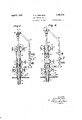
- Fig. 1 is a sectional elevation indicating the complete apparatus required both for flowing the well normally and for lowering tubing during flow, the break above the intermediate valve indicating the dividing line between the permanent and temporary equipment;
- Fig. 2 is a cross section taken approximately on the line 22 of Fig. 1;
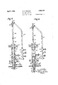
- Fig. 3 is a vertical sectional elevation showing more or less diagrammatically one of the steps in removing the. landing packer and landing mandrel while maintaining gas circulation and preparatory to introduction of tubing, the upper packing ram being closed and the suspended string of tubing being landed on the lower packing ram;
- Fig. at isa similar View showing the landing mandrel and its packing disconnected from the string of tubing and in an elevated position above the intermediate valve which has been closed to retain the gas pressure being applied to the tubing and to permit the removal of the landing mandrel and its packer through the upper ram;
- Fig. 5 is a similar view showing a new section of tubing attached,to the lowering stem and in posit-ion about to be threaded into the tubing suspended on the lower ram, the upper ram being closed; the upper gas control valve has been opened to insure introduction of gas through the lowering stem following the attachment of the latter to the suspended tubing; the lower gas control valve will be closed before opening the lower ram in order to prevent introduction of gas into the annular oil chamber below the ram;
- Fig. 6 illustrates the position of the valves while lowering a collar or coupling through the lower ram and slipping the new tubing section through the upper ram, the lower gas control valve being closed to prevent the passage of gas into the annular oil chamber below the ram.
- Fig. 7 illustrates a succeeding position
- Fig. 8 disclosed a modified form of gas confor intermittent gas introduction
- Fig. 9 illustrates a modified structure for normal support of the tubing.
- Fig. 1 the entire physical structure required for operation according to the present invention is there shown. That portion which is required on the well as a permanent fixture to be employed for normal gas lift is shown mounted upon the well casing 1A, and that portion which is required to be attached-for the lowering of the tubing 16 is shown as elevated somewhat there above and aligned for lowering into operative position.
- the tubing lowering assembly includes massive valves A and B of the ram type and a gate'valve C disposed therebetween.
- the valves A and B will hereinafter usually be referred to as rams rather than as valves.
- the ram A is threaded upon a special head 15 mounted upon casing 14 and a short section of pipe 17 serves to mount the gate valve C upon said ram A.
- the ram is carried upon a pipe section 18 WhlCh 1s adapted to be threaded into the upper end of the housing of gate valve C when the apparatus is being prepared for lowering tubing.
- the ram A is provided with a gas supply connection 20 controlled by valve 21 for normally supplying to the well high pressure gas obtained from a gas main 22.
- a connection 23 also leading from the main 22 is provided with a valve 24 which is closed normally but permits temporary introduction of gas to the tubing by a different route during those intervals when the tubing is connected up for the actual lowering (or raising) thereof.
- Such temporary gas introduction is made by way of a hose 25 leading to a swivel 26 adapted to be supported in the.
- the swivel 26 carries the lowering stem or slip joint 28.
- This stem is conveniently in the form of a short length of tubing which has the same diameter as the tubing 16 and is adapted to extend through the rams A and B and gate valve C and to be connected with the upper end of a landing mandrel or tubing support M which is normally carried upon a suspending packer P normally restin in the casing head 15 and supporting the tubing 1 16 through the medium of a coupling 30.
- ram A is in open position as shown in Fig. 1
- the gate valve C is in closed position to prevent escape of gas
- the valve 24 is closed
- gas under pressure is supplied from themain 22 past the open valve 21 and by way of the connection 20 to the upper side of the ram A above the jaws thereof and thence through the ram into mandrel M and tubing 16 which is suspended on the packer P.
- the oil and gas are discharged from the head 15 by way of a conduit 32.
- the valves A and B which as above indi cated are of the ram type, are each provided with two jaws 35 reciprocating in'suitable guideways and provided-with suitable packing as at 36. Said jaws are adapted to be actuated either by hand screws 37 as shown, or hydraulically or otherwise as Well understood or desired. ⁇ Vhen in wide open position as indicated in Fig. 1, the spread of the jaws 35 is sufficient to pass the landing packer P as well as the mandrel M and couplings 30 and 30".
- the opposing faces of these jaws have semi-circular passages whereby the jaws are adapted to receive and be closed about the lowering stem 28 or the tubing 16, or an additional tubing length 16'.
- the packing 36 assures a gas-and-oil-tight engagement which is necessary during tubinglowering operations .because the packer P will havebeen removed, as presently to be described.
- Figs. 3 to 6, inclusive are diagrammatic representations of successive steps employed.-
- a left hand thread connection may be'used requiring the temporary use of a special left hand threaded stem in place of stem 28 for the removal of mandrel M.
- the succeeding operations are largely reversals of the operations previously described. They consist in lowering the new tubing length 16 through the open ram B while the various valves are in the position of Fig. 4.
- the ram B is then closed about the tubing length 16 as in Fig. 5, the gate valve C is opened, the gas control valve 24 is opened, and the tubing length 16 is forced downward through the gate C in alignment with the coupling 30 which is supported upon the jaws 35 of ram A.
- valve 21 is closed. In general, this is the same position as that of Fig. 3, except that section 16 replaces the landing mandrel M. Also it is the position of Fig. (3 except for ram A and coupling 30. It will be particularly noted, however, that as indicated in Fig. 5 the valve 24 should be opened before the new tubing length 16 is threaded into the collar 30, in order to insure against any interruption of gas circulation. It will also be noted that for the same reason there is a stage when both valves 21 and 24 willin practice be open. Said tubing 16 having been threaded into coupling 30, valve 21 will be closed. The stem 28 with the attached tubing 16 is next I elevated slightly through the medium of bail 27 to remove the weight of the tublng string 16 from the jaws of ram A. Said jaws are then opened, as
- tubing can be as readily raised in a well to remove tubing lengths while continuing gas circulation and maintaining gaslift flow.
- the only difference in operation will be that the tubing will be elevated through therams instead of lowered and the rams will be manipulated to pass the couplings 30 upward instead of downward.
- the hose 25' body-if If required to cutoff oil-fiow-atin't'ervalsduring the" oil line 32l may'have a' packing rams A, B and the gate valve C are employed as possible means for accomplishing the corresponding functions, it wouldv nevertheless be sufiicient for the purposes of the invention to employ any serviceable type of valve as a substitute for the gate valve C, and to use other types of packers in place of the rains.
- packers could for example be rubber bags or other. inflatable or compressible devices which would serve to seal or pack the tubing.
- any substitute for the jaws of the lower ram as supporting means for the suspended tubing could be employed.
- the rams could be operated otherwise than manually; for instance they could be power operated by steam or gas pressure or by hydraulical pres sure or electric motors.
- a method for lowing tubing in a well flowing by gas lift comprising the steps of applying gas under pressure to said tubing to flow the well, applying gas under pressure to a tubing length to be connected to the tubing and discontinuing said first mentioned gas introduction to be lowered, connecting said tubing length to said tubing, and lowering the tubing and tubing length simultaneously with the introduction of gas through said tubinglength.
- a method of lowering or raising tubing in a gas lift well in which the tubing is suspended comprising successively introducing or withdrawing lengths of tubing through an aligned assembly of valves adapted to respectively pass and pack the tubing, attaching or removing said lengths to or from the suspended tubing, intermittently lowering or raising the tubing and supplying gas under pressure to said assembly into the well to continue gas lift operations during the time when the tubing being lowered or raised is disconnected from the tubing suspended in said wall.
- a method for raising or lowering tubing in a well flowing by the gas lift method while continuing gas lift through an assembly havingpacking means comprising the steps of introducing gas into the assembly and thence to the tubing, introducing a hollow stem into,
- a method for lowering tubing into a well flowing by the gas lift method comprising the steps of suspending the tubing in the assembly, introducing gas into the lower portion of the assembly through a gas connection and thence to the tubing, introducing a length of tubing into said assembly, packing said tub ing length, connecting a hollow stem with said length 'of tubing by means of a joint, supplying gas under pressure to said stem and tubing length, moving the tubing length through the packing into engagement with I the suspended tubing, connecting thetubing length with said suspended tubing thereby flowing the well by way of the stem, relieving the suspension of the tubing, lowering said tubing length through said packing simultaneously with flow of gas through the stem until the joint between the stem and the tubiug reaches said suspending means. engaging said joint with the suspending means of the 1 assembly, disconnecting the stem, removing pressure from the stem and applying it through said gas connection, cutting ofi gas pressure from the packing, and removing the stem.
- a device for moving tubing in a gas lift well comprising a, valve assembly adapted to be mounted on a Well casing and to pass the tubing to and from the well and a fluid connection to said assembly for passing fluid during operations.
- a device for lowering tubing in a casing in a gas lift well comprising a valve assembly adapted to pass tubing therethrough, said assembly being adapted to be mounted on said casing, a tubing lowering stem adapted to pass through said valve assembly for connection with said tubing, means to sup- 'the tubing and the lowering stem.
- a structure according to claim 10 containing a gas supplying means connected with the lowering stem.
- a device for moving tubing in a gas lift well comprising a valve assembly mounted on a casing and adapted to pack and pass tubing therefhrough, means adapted to be projected into and packed by said assembly to move the tubing, means to communicate with the tubing and pass fluid therethrough, and a fluid connection from said casing.
- a manifold for moving tubing in a gas lift well while maintaining circulation of gas in the well comprising a. valve assembly adapted to be mounted upon a well casing-and to pass tubing therethrough, a connection to the side of the-assembly for passing fluid, a tubing-handling member adapted to be passed through the assembly into engagement with ond connection attached to said member for passing fluid by way of said member when connected to the tubing.
- a structure for moving tubin in a gas lift well while introducing gas to t e tubing comprising a valve assembly adapted to pass'tubing therethrough and pack the same against escape of gas, a stem adapted to be passed into and packed vby 1 said assembly and to be connected with suspended tubing for moving the latter, and a gas connection to said stem for supplying gas to the tubing by way of the stem.
- a structure for moving tubing in a gas lift well while introducing gas to the tubing comprising a valve assembly adapted to pass tubing therethrough and pack the valve, and a second gas supplying connection leading to the assembly below said control valve.
- A'device for. lowering tubing in gas lift wells during flow of the wells by gas lift comprising a well casing, a member mounted on said casing and including means to suspend tubing therefrom and to pack said tubing, a valve connected above said member, packing means above said valve to receive and pass tubing lengths, means to supply gas under pressure between the member and the valve, means to supply gas under pressure to a tubing length being lowered through the packing means, and a fluid connection leading from said casing.
- a structure for lowering tubing in gas lift Wells comprising a well casing, an assembly mounted upon said casing, means carried by said assembly adapted “to support said tubing during certain operations connected with tubing lowering procedure and to pack said tubing during such operations, a gascontrol valve connected in the assembly above said means, a tubing lowering member adapted to be passed through said valve into engagement with the tubing, a gas connection above said means for supplylng as to the tubing, and a fluid conduit leading from the well casing.
- a structure for moving tubing depending in a gas lift well while maintaining gas flow to the well comprising a device adapted to be mounted on the well casing, said device including means to suspend said tubing and to pack said tubing, valve means carried above said jacking member, a tubing moving member adapted to be projected through said'valve means, said valve means being adapted when open to pass said tubing moving member, a connection to supply gas to said tubing moving member, and a connection to supply gas between the valve means and the packing member.
- a structure for lowering tubing in a gas lift well comprising a member adapted .to be connected with a well casing'and including means to pack depending tubing, a valve carried by and disposed above said packing means, and a second packer disposed above and carried by said member, and adapted to pass tubing and tubing couplings, a tubing movingmember adapted to be projected through the upper packer and through said valve, and a connection for supplying gas above the lower packing means.
- a manifold adapted to be connected to a gas lift well casing for moving tubing therein while maintaining gas circulation through the well comprising a valve assembly adapted to pass tubing therethrough, means adapted to be projected into the assembly to engage the tubing, and two gas connections, said assembly comprising a lower packing valve adapted to pass tubing, an upper packing valve adapted to pass tubing, a gas control valve between the packing valves, one gas connection leading to the assembly below the gas valve and the other gas connection leading to the tubing engaging means.
- a structure for moving coupled tubing in a gas lift well comprising a tubing handling stem, a valve assembly adapted to pass through said stem and tubing and tubing couplings, a connection for supplying gas to said assembly and tubing, said assembly including a lower valve adapted to support a string of tubing suspended therethrough, an upper valve adapted to receive and pack said stem, and a gas intercepting valve between said upper and lower valves adapted when open to pass said stem and additional tubing lengths.
- a tubing lowering manifold for a gas lift well comprising a valve assembly, a lowering stem adapted to be passed through said assembly, a gas connecl gas connection leads to the tubing valve being adapted tosupport and pack tubing suspended inthe well, the upper packing valve being adapted to receive and pack said stem, and the gas valve being adapted when closed to cut off gas and when open to pass said stem. 4
- a gas lift manifold for lowering tubing in a gas lift well comprising a packing ram I packed by the upper packing means and to be connected with a length of tubing, means to supply gas under pressure to a point below the valve for supplying gas to the tubing suspended from the ram, and means to supply gas under pressure to the stem.
- a structure for lowering tubing in a gas lift well comprising a casing head adapted normally to receive a tubing support-ing mandrel and its packer, a valve assembly, a
- tubing lowering member to be projected therethrough, and means for supplying gas during operations connected with tubing lowering procedure to the assembly and said tubing lowering member, said assembly, comprising a lower valve member adapted to be mounted upon the casing head, an intermediate valve positioned above the lower valve member and an upper valve positioned above the intermediate member, said valves being 3 adapted to pass said tubing lowering member and also to pass said tubing supporting mandrel and its packer,
- a well casing a tubing depending in said casing, a valve assembly 40 mounted on said casing, a fluid conducting line leading from said casing, said assembly including means to support said tubing, a fluid conduit, and tubing handling means "adapted to be passed through said assembly to engage said tubing and connect the fluid conduit therewith.
- a structure adapted to be attached to a gas lift well for moving tubing therein comprising a valve assembly, a stem adapted to be passed therethrough to engage suspended tubing, and a single gas connection for said assembly.
- a structure adapted to be attached to a gas lift well for lowering tubing therein with intermittent gas circulation to the well comprising a valve assembly, a stem adapted to be passed through said assembly to engage suspended tubing, and a single gas connec- 00 tion, said valve assembly including a gas valve adapted when open to pass tubing lengths, and means adapted when closed to pack and pass such lengths,'said single gas connection being attached to the side of said 65, valve assembly below the gas valve for sup- 'a fluid connection to said assembly, a casing on which said assembly is mounted and a fluid connection for said well casing.
- a structure for moving tubing in a flowing well comprising an assembly havin a plurality of valves adapted to pass and pack tubing against escape of fluid, said assembly also including means to suspend tubing in the well, a stem adapted to be passed through said assembly to engage and move the tubing, a well casing head on which said assembly is mounted, a landing mandrel and packing means adapted to support tubing in said head, said mandrel being adapted to be engaged by the stem, and a fluid connection to said casing head.
- a method of lowering or raising tubing in a gas lift well, in which the tubing is suspended comprising successively introducing or withdrawing lengths of tubing through an ligned assembly of valves adapted to respectively pass and pack the tubing, attaching or removing said lengths to or from the suspended tubing, intermittently lowering or raising the tubing, and supplying gas under pressure to the said tubing lengths while the latter are attached to the suspended tubing to promote gas lift operations during periods of such attachment.
- a method of lowering or raising tubing in a gaslift well, in which the tubing is suspended comprising successively introducing or withdrawing lengths of tubing through an aligned assembly of valves adapted to respectively pass and pack the tubing, attaching or removing said lengths to or from the suspended tubing, intermittently lowering or raising the tubing, and supplying gas under pressure to said tubing lengths to effect gas lift operations during periods when tubing lengths are packed in said assembly.
- Patent No. 1,852,716 Granted April 5, 1932, to
Landscapes
- Life Sciences & Earth Sciences (AREA)
- Engineering & Computer Science (AREA)
- Geology (AREA)
- Mining & Mineral Resources (AREA)
- Physics & Mathematics (AREA)
- Environmental & Geological Engineering (AREA)
- Fluid Mechanics (AREA)
- General Life Sciences & Earth Sciences (AREA)
- Geochemistry & Mineralogy (AREA)
- Pipeline Systems (AREA)
Description
April 5, 1932.
S. H. GRINNELL GAS LIFT MANIFOLD Filed Sept. 8, 1930 4 Sheets-Sheet l INVENTOR.
JHGrz'nneZZ BY 4 6 ATTORNEY.
S. H. GRINNELL GAS LIFT MANIFOLD April 5, 1932.
4 Sheets-Sheet 2 Filed Sept 8, 19:50
INKENTOR. J/i GrzzmeZZ BY W TTORNEY.
April 5, 1932- s. H. GRINNELL 1,852,716
GAS LIFT MANIFOLD Filed Sept. 8, 1930 4 Sheets-Sheet 3 INVENTOR.
SH Grz'rmeZZ I\ 26 J Aw A ORNE Y.
April 5, 1932.
s. H. GRINNELL GAS LIFT MANIFOLD Filed Sept. 8, 1930 4 Sheets-Sheet 4 INIfENTOR. JHGrzn me 12 lax @4 4,
ATTORNEY.
Patented Apr. 5, 1932 UNITED STATES PATENT OFFICE FORNIA SAMUEL H. GRINNELL, OF LOS ANGELES, CALIFORNIA, ASSIGNOR TO UNION OIL COM- r-ANY or cnmromvm, or nos mourns, CALIFORNIA, A CORPORATION or arm- GAS LIFT MANIFOLD Application filed September 8, 1930; Serial No. 480,327.
This invention relates to devices for lowering tubing in oil wells and especially in wells which are being flowed by the well known gas-lift metho The principal object of the invention is to provide a method and a structurewhereby the tubing may be lowered in a gas-lift well toa lower level durin and simultaneously with introduction of the high pressure gas which is being employed to flow the well.
Thus no opportunity can be aflorded for losing the well, i. e. total or material loss-of natural flow of the oil from the formation into the well hole, assometimes happens when the circulation of gas is interrupted for a period of time suflicient to lower the tubing. It is common practice to recover o1l from deep wells by the introduction of high pressure gas into the well either through the casing or through a central flow tubing in such fashion that the gas in its passage around the lower end ofthe tubing picks up the 011, atomizes it and carries it to the surface.
A When first placing a well on gas lift, the oil initially stands much higher in the well than is desired for subsequent flow. Often the available gas pressure is sufliclent to overcome charge, then remove the" gas connection to gain access to the tubing thereby resulting in loss of gas pressure in the well, then lower the tubing to'a greater depth, and finally restore gascirculation before the formation pressure succeeded in building up thehead tos'uch a value'that it cou'ldnot be overcome.
However in most cases the ee rn ew of oil into the well is too rapid for such procedure tob'e followed jAn theiPIiCtice has been to ploy sui blev e ih l arr su on' the since' no means ever been devised 'wh'er by; the circulat on of the as' "could 'b upper end well while lowering the tubing, but f flow of the well was necessarily interrupted. The very common result of this method was that the well sanded up, caved in, or for some other reason had its physical condition so a'fiected that upon restoring gas circulation after lowering the tubing it was found that the well had been substantially lost or its production very seriously and permanently impaired.
In view of these facts it has been a desideratum ever since the gas-lift method of flowing wells became popular, to devise some safe, practical and adequate means for lowering the tubing in the well to greater depths while maintaining the flow by gas-lift, in order that the oil head could be discharged substantiab ly as fast as the tubing was lowered. So far as is known, the present invention constitutes. e the first successful accomplishment of this 1 character and is the first to meet the need.
The invention resides in a method and in a means whereby the circulation of high pressure gas may be positively maintained a gas-lift well simultaneouslywith and during the entire procedure of lowering the tub- The operation ing to lower operating levels. of lowering the tubing consists in introducing additional lengths of tubing into the well.
According to a preferred method and con struction the step of maintaining g'as circu-,
lation is accomplished by lowering the tubing through an assembly of valves having in combination a permanent connection for supplying gas under pressuredirectlyto the lower portion of the valve assembly in 'orderthat the gas may be normally applied to the open I of thestrin -g of tubing normally suspended in the well, and also in combination with 'a sec'ondfconnection whereby gasmay be 'sumgiliedto the thusc'ons'titute ajmanifold for the selective sembly 'are conveniently in the form of packc e p rm t-a 1 e e hr eeh Je t e W l .v ngths. e
21 11 hi a apted tubing'string by way of additional lengths" of tubing when" said I lengths are" connected 'with'the string and are "being lowered therewith. This valve aS Sembly and "the two gas connections mentioned;
I ficiently wide to pass the tubing couplings be added and of a hollow lowering stem or slip joint which forms a part of the second gas connection above mentioned. This stem, which is conveniently merely a length of tubing, preferably has the same diameter as the well tubing and serves as a tool to which the additional lengths of tubing are to be connected and by which they are to be lowered. Usually hereinafter it will be known as the lowering stem. The ram-type valves con tain two heavy packing jaws adapted to be closed about the stem and tubing lengths to make gas-tight joints therewith and at the same time permit the stem and tubing to be slipped therethrough. Usually said valves will be referred to merely as frams. These rams are further adapted to be opened sufand also to pass a landing or suspending mandrel and its packer, which mandrel and packer normally function to support the tubing in the casinghead and thereby suspend said tubing in the well. An intermediate valve, such as a gate valve, serves to completely cut ofl gas thereabove so as to prevent escape of gas through the upper packing ram during the interval when it is necessary to open the said upper ram for the introduction or removal of the lowering stem and/or any parts attached thereto. Such parts are the landing mandrel and the additional lengths of tubing being introduced, and are selective- 1 attached to said stem at various stages of t e procedure. The lower ram serves not only as a packing device but also as an agent for temporarily suspending the whole string of tubing within the well by catching the uppermost coupling of the tubing string upon the upper edges of the jaws of the ram during those intervals when the lowering 'stem is being withdrawn and when a new length of tubing is being connected to the string. Both the gas connection to the valve. assembly and the gas connection to the lowering stem are provided with valves in order that the gas flow may be controlled as desired. By selective manipulation of these gas valves and of the two packing rams and the intermediate valve, tubing lengths may be successively added and the tubing lowered with maintenance of gas introduction throughout the entire procedure.
Broadly stated, the invention, as considered in the light of the above disclosures, comprises the combination of an assembly of aligned valves adapted to pass tubing, with a plurality of gas connections for said assembly adapted for selectively introducing gas to the assembly at different points during various operations in order to maintain circulation of high pressure gas to the well throughout said operations. The invention also comprises the combination of said valve assembly and gas connections, wherein one connection includes a tubing-lowering stem which is adapted to be passed through the valves of said assembly, which is also adapted to have additional tubing lengths attached thereto, and which is further adapted to introduce said lengths into said assembly, to attach them to the tubing which normally hangs in the well, and to lower the entire tubing string. The invention may be also stated as comprising the combination of a valve assembly adapted tobe secured to a well casing and including a plurality of valves adapted to pass tubing and to retain gas pressure under various tubing lowering conditions, a hollow lowering stem adapted to be passed through said valves for introducing additional tubing and for removing and restoring equipment employed to suspend the tubing string during normal operation of the well, a connection to supply gas to a lower portion of the head during certain operations, and a second gas connection for supplying gas to said lowering stem.
More specifically the invention comprises a manifold which includes an assembly of aligned valves and two gas connections for supplying gas to the assembly, wherein upper and lower valves, in the form of rams for example, are adapted to seal ofi? tubing projected-therethroughand at the same time to permit slippage of the tubing, and wherein an intermediate valve is adapted to be opened to pass tubing and to be closed to completely cut oil passage of gas through the valve when the tubing has been removed from its path, one of the gas connections including a hollow lowering stem adapted to he slipped through said upper and lower valves and to be packed thereby against gas passage during various operations. The invention also resides in the method of controlling the various valves and the passage of gas during the removal of the normal tubing-suspending equipment and during the introduction of additionaltubing.
The invention resides further in the method of lowering tubing into a well or removing it therefrom while maintaining gas introduc Fig. 1 is a sectional elevation indicating the complete apparatus required both for flowing the well normally and for lowering tubing during flow, the break above the intermediate valve indicating the dividing line between the permanent and temporary equipment;
nection to the manifold Fig. 2 is a cross section taken approximately on the line 22 of Fig. 1;
Fig. 3 is a vertical sectional elevation showing more or less diagrammatically one of the steps in removing the. landing packer and landing mandrel while maintaining gas circulation and preparatory to introduction of tubing, the upper packing ram being closed and the suspended string of tubing being landed on the lower packing ram;
Fig. at isa similar View showing the landing mandrel and its packing disconnected from the string of tubing and in an elevated position above the intermediate valve which has been closed to retain the gas pressure being applied to the tubing and to permit the removal of the landing mandrel and its packer through the upper ram;
Fig. 5 is a similar view showing a new section of tubing attached,to the lowering stem and in posit-ion about to be threaded into the tubing suspended on the lower ram, the upper ram being closed; the upper gas control valve has been opened to insure introduction of gas through the lowering stem following the attachment of the latter to the suspended tubing; the lower gas control valve will be closed before opening the lower ram in order to prevent introduction of gas into the annular oil chamber below the ram;
Fig. 6 illustrates the position of the valves while lowering a collar or coupling through the lower ram and slipping the new tubing section through the upper ram, the lower gas control valve being closed to prevent the passage of gas into the annular oil chamber below the ram.
Fig. 7 illustrates a succeeding position;
Fig. 8 disclosed a modified form of gas confor intermittent gas introduction; and
Fig. 9 illustrates a modified structure for normal support of the tubing.
Referring particulary to Fig. 1 the entire physical structure required for operation according to the present invention is there shown. That portion which is required on the well as a permanent fixture to be employed for normal gas lift is shown mounted upon the well casing 1A, and that portion which is required to be attached-for the lowering of the tubing 16 is shown as elevated somewhat there above and aligned for lowering into operative position. The tubing lowering assembly includes massive valves A and B of the ram type and a gate'valve C disposed therebetween. For convenient distinction the valves A and B will hereinafter usually be referred to as rams rather than as valves. 'The ram A is threaded upon a special head 15 mounted upon casing 14 and a short section of pipe 17 serves to mount the gate valve C upon said ram A. The ram is carried upon a pipe section 18 WhlCh 1s adapted to be threaded into the upper end of the housing of gate valve C when the apparatus is being prepared for lowering tubing. The ram A is provided with a gas supply connection 20 controlled by valve 21 for normally supplying to the well high pressure gas obtained from a gas main 22. A connection 23 also leading from the main 22 is provided with a valve 24 which is closed normally but permits temporary introduction of gas to the tubing by a different route during those intervals when the tubing is connected up for the actual lowering (or raising) thereof. Such temporary gas introduction is made by way of a hose 25 leading to a swivel 26 adapted to be supported in the.
well rig or derrick by means of a bail 27. The swivel 26 carries the lowering stem or slip joint 28. This stem is conveniently in the form of a short length of tubing which has the same diameter as the tubing 16 and is adapted to extend through the rams A and B and gate valve C and to be connected with the upper end of a landing mandrel or tubing support M which is normally carried upon a suspending packer P normally restin in the casing head 15 and supporting the tubing 1 16 through the medium of a coupling 30.
During normal operation of the well, ram A is in open position as shown in Fig. 1, the gate valve C is in closed position to prevent escape of gas, the valve 24 is closed, and gas under pressure is supplied from themain 22 past the open valve 21 and by way of the connection 20 to the upper side of the ram A above the jaws thereof and thence through the ram into mandrel M and tubing 16 which is suspended on the packer P. The oil and gas are discharged from the head 15 by way of a conduit 32.
The valves A and B, which as above indi cated are of the ram type, are each provided with two jaws 35 reciprocating in'suitable guideways and provided-with suitable packing as at 36. Said jaws are adapted to be actuated either by hand screws 37 as shown, or hydraulically or otherwise as Well understood or desired. \Vhen in wide open position as indicated in Fig. 1, the spread of the jaws 35 is sufficient to pass the landing packer P as well as the mandrel M and couplings 30 and 30". The opposing faces of these jaws have semi-circular passages whereby the jaws are adapted to receive and be closed about the lowering stem 28 or the tubing 16, or an additional tubing length 16'. The packing 36 assures a gas-and-oil-tight engagement which is necessary during tubinglowering operations .because the packer P will havebeen removed, as presently to be described.
Figs. 3 to 6, inclusive, are diagrammatic representations of successive steps employed.-
III
packer P and running in new lengths of tubing.
Operation The operations required for lowering the tubing will now be described. \Vith the normal operating equipment A, C, M, P, 20, 22, and valves 21 and 2st in the positions indicated in Fig. 1, the pipe section 18 carrying the upper ram B is threaded into the gate valve housing C. The hose 25, which is attached to the swivel 26 suspended in the derrick, is connected with the gas valve 24, and the slip joint or lowering stem 28 is passed through the open aws of the ram B into a position approximately as'indicated in Fig. 1. The aws 35 of ram B are then moved into packing position against the stem 28, the
gate valve 0 is opened, and the gas-control valve 24: is also opened; see Fig. 3. Lowering stem 28 is now forced downward through the gate valve C and into engagement with the landing mandrel M whereupon said stem is threaded into firm engagement with the threads in the upper end of said mandrel. Since the well is now being flowed by passage of the gas through valve 24, hose 25, stem 28 and thence to the tubing 16, the valve 21 may be closed as indicated in Fig.3. This closing of valve 21 is necessary to insure against subsequent introduction of high pressure gas into the space between-the casing 14 and tubing 16. The next step is the elevation of the stem 28 and tubing 16, together with the landing mandrel M and packer P, into the position of Fig. 3 so that the coupling 30 on the tubing 16 is just above the jaws 35 of the ram A. Said jaws 35 of ram A are then moved into the closed position of Fig. 3, and the coupling 30is allowed to settle upon the jaws so that the latter support the entire weight of the suspended tubing. WVrenches are next applied to the stem 28 to unscrew the land ng mandrel M from coupling 30. To insure that the joint between the mandrel M and coupling 30 is broken ratherthan the joint between stem 28 and mandrel M, a special tapered thread or mutilated thread, or the like. mav be employed in the upper end of the landing mandrel M, or a left hand thread connection may be'used requiring the temporary use of a special left hand threaded stem in place of stem 28 for the removal of mandrel M. Having freed the landing mandrel M from thecoupling 30 sa d mandrel M and its packer P are lifted into a position above the gate valve 0.
During the operations just described. the travel of the gas has been through the hose 25 and stem 28. Sinceit is now desired to remove the stem 28, it is necessary first to open the valve 21 to supply gas below the gate valve C and then to close the valves 24 and C as indicated in Fig. 4. The upper ram B is next opened and the landing mandrel M and its acker P are withdrawn therefrom and then removed from the stem 28.
The structure has now been prepared for actually running in additional lengths of tubing. A new length (or lengths) of tubing 16 having a coupling 30 secured on its upper end, is next mounted on the lower end of the lowering stem 28 (see Fig. 5) through the medium of said coupling 30. The succeeding operations are largely reversals of the operations previously described. They consist in lowering the new tubing length 16 through the open ram B while the various valves are in the position of Fig. 4. The ram B is then closed about the tubing length 16 as in Fig. 5, the gate valve C is opened, the gas control valve 24 is opened, and the tubing length 16 is forced downward through the gate C in alignment with the coupling 30 which is supported upon the jaws 35 of ram A. Said tubing 16 is then threaded into said coupling 80 and valve 21 is closed. In general, this is the same position as that of Fig. 3, except that section 16 replaces the landing mandrel M. Also it is the position of Fig. (3 except for ram A and coupling 30. It will be particularly noted, however, that as indicated in Fig. 5 the valve 24 should be opened before the new tubing length 16 is threaded into the collar 30, in order to insure against any interruption of gas circulation. It will also be noted that for the same reason there is a stage when both valves 21 and 24 willin practice be open. Said tubing 16 having been threaded into coupling 30, valve 21 will be closed. The stem 28 with the attached tubing 16 is next I elevated slightly through the medium of bail 27 to remove the weight of the tublng string 16 from the jaws of ram A. Said jaws are then opened, as
indicated in Fig. 6, and the weight of the strlng is allowed to pull the new tubing section 16 slowly down through the closed packing jaws of the ram B until the coupling 30 of sectmn 16 is just above ram 13, and couhng 30 is well below ram A. Ram A will be closed tightly about the tubing length 16, v
as indicated in Fig. 7, and ram B opened for passage of coupling 30 which is then allowed to descend by slippage of section 16 through aws of ram A until said coupling 30 is adjacent these jaws. Ram B is then closed. If a second tubing length 16 has been connected below stem 28 the operations will be' repeated to pass the couplings through the rams and lower said sc condlength. In order to introduce another length (or lengths) of tubing, the coupling 30 is rested upon ram A, and (ram B having been closed) the stem 28 is unthreaded from coupling 30, gas is turned in through valve 21 and cut off through valve 24, stem 28 is lifted above gate 0 which is then closed, and ram B is opened for removal of stem 28, whereby the parts again assume the relation shown in Fig. l
be lowered into a gas-lift well without the slightest interruption in the application of the high pressure gas required to maintain normal flow of the well. As rapidly as the lower end of the tubingis passed into the oil body in the well the gas flow willdischarge the corresponding head, and there will be no interference whatever with production. At the end of the tubing lowering operations the landing mandrel M and its packer P are restored and lowered into their seat in the casing head 15 by a similar operation.
Also, tubing can be as readily raised in a well to remove tubing lengths while continuing gas circulation and maintaining gaslift flow. The only difference in operation will be that the tubing will be elevated through therams instead of lowered and the rams will be manipulated to pass the couplings 30 upward instead of downward.
' It is obvious that the flow of the well may be reversed, from that thereinbefore' indicated, that is, gas may normally be introduced through the casing and the oil flowed out through the tubin may be eliminated as illustrated in Fig. 8, so that gas introduction can take place only intermittently by way of the connection 20 and valve 21. Under these conditions the valve 21 will be open at all times that the ram A is closed in order that gas introducr feia midwaytion may take place during maximum periods of time. WVith this "arrangementthe stem 28.
will be sealed either by means of a plug or by employment of a solid stem in order to prevent loss of gas therethrough. Another arrangement for intermittent operation, which is perhaps preferable for most wells, is
i omitted Instead of supplying gas continuously during'the various operations, the hose 25' body-if If required to cutoff oil-fiow-atin't'ervalsduring the" oil line 32lmay'have a' packing rams A, B and the gate valve C are employed as possible means for accomplishing the corresponding functions, it wouldv nevertheless be sufiicient for the purposes of the invention to employ any serviceable type of valve as a substitute for the gate valve C, and to use other types of packers in place of the rains. Such packers could for example be rubber bags or other. inflatable or compressible devices which would serve to seal or pack the tubing. In the latter instance any substitute for the jaws of the lower ram as supporting means for the suspended tubing, could be employed. Further, the rams could be operated otherwise than manually; for instance they could be power operated by steam or gas pressure or by hydraulical pres sure or electric motors.
It is also to be understood that the specific disclosures made herein are for the purpose of illustrating the invention and are not to be consideredas limiting since variations within the scope of the invention may be made readily by those skilled in the art.
aligned assembly of valvesadapted to respectively pass and pack the tubing, attaching or removing said lengths to or from the suspended tubing, intermittently lowering or raising the tubing, and supplying gas under pressure to said assembly. and into the well attachment'or subsequent to the disconnecintroduction taking place between the suc-' I 'cessive lowering or raising operat1o'ns.-
to continue gas lift operations prior to said. tokeep the valve 21 closed and to usethe tion of the lengths of tubing lowered or 3. A method according to claim '1 wherein the gas is intermittently supplied to the suspended tubing, the introduction taking' place during lowering" or raising operations.'=
-- IV 1.; Amethod for lowering or raising tubingf in-a' gas li ft wen while continuing gas lift in which fihe' tubing '-1s suspended comprising successively introducing or remov ng lengths of tubin'g through an 'alignednsseinbly of valves adapted respectivelyto pass and pack 'thet1'1bing, attaching or disconnecting said" A modified arrangement foririoiintingthe lengths toorfrCin't'lie suspended tubing; in-' ternii-t ently lowering or raising aie tubing,
assembly and into the tubing while sections are disconnected and directly into the tubing while the sections are connected.
5. A method for lowing tubing in a well flowing by gas lift, comprising the steps of applying gas under pressure to said tubing to flow the well, applying gas under pressure to a tubing length to be connected to the tubing and discontinuing said first mentioned gas introduction to be lowered, connecting said tubing length to said tubing, and lowering the tubing and tubing length simultaneously with the introduction of gas through said tubinglength.
6. A method of lowering or raising tubing in a gas lift well in which the tubing is suspended, comprising successively introducing or withdrawing lengths of tubing through an aligned assembly of valves adapted to respectively pass and pack the tubing, attaching or removing said lengths to or from the suspended tubing, intermittently lowering or raising the tubing and supplying gas under pressure to said assembly into the well to continue gas lift operations during the time when the tubing being lowered or raised is disconnected from the tubing suspended in said wall.
7. A method for raising or lowering tubing in a well flowing by the gas lift method while continuing gas lift through an assembly havingpacking means comprising the steps of introducing gas into the assembly and thence to the tubing, introducing a hollow stem into,
said assembly, packing said stem, supplying gas under pressure to said stem, simultaneously moving the stem through the packing, connecting the stem with the tubing, flowing the well by way of thestem, and moving the connected stem and packer. I
8. A method for lowering tubing into a well flowing by the gas lift method, the well carrying an assembly including means to suspend and pack the tubing, comprising the steps of suspending the tubing in the assembly, introducing gas into the lower portion of the assembly through a gas connection and thence to the tubing, introducing a length of tubing into said assembly, packing said tub ing length, connecting a hollow stem with said length 'of tubing by means of a joint, supplying gas under pressure to said stem and tubing length, moving the tubing length through the packing into engagement with I the suspended tubing, connecting thetubing length with said suspended tubing thereby flowing the well by way of the stem, relieving the suspension of the tubing, lowering said tubing length through said packing simultaneously with flow of gas through the stem until the joint between the stem and the tubiug reaches said suspending means. engaging said joint with the suspending means of the 1 assembly, disconnecting the stem, removing pressure from the stem and applying it through said gas connection, cutting ofi gas pressure from the packing, and removing the stem.
9. A device for moving tubing in a gas lift well comprising a, valve assembly adapted to be mounted on a Well casing and to pass the tubing to and from the well and a fluid connection to said assembly for passing fluid during operations.
10. A device for lowering tubing in a casing in a gas lift well comprising a valve assembly adapted to pass tubing therethrough, said assembly being adapted to be mounted on said casing, a tubing lowering stem adapted to pass through said valve assembly for connection with said tubing, means to sup- 'the tubing and the lowering stem.
12. A structure according to claim 10 containing a gas supplying means connected with the lowering stem.
13. A device for moving tubing in a gas lift well comprising a valve assembly mounted on a casing and adapted to pack and pass tubing therefhrough, means adapted to be projected into and packed by said assembly to move the tubing, means to communicate with the tubing and pass fluid therethrough, and a fluid connection from said casing.
14. A structure according to claim 13 wherein the first mentioned fluid connection is connected to the tube moving means.
15. A structure according to claim 13 wherein the first mentioned fluid connection leads direttly to the body of the valve assembly.
16. A manifold for moving tubing in a gas lift well while maintaining circulation of gas in the well, comprising a. valve assembly adapted to be mounted upon a well casing-and to pass tubing therethrough, a connection to the side of the-assembly for passing fluid, a tubing-handling member adapted to be passed through the assembly into engagement with ond connection attached to said member for passing fluid by way of said member when connected to the tubing. c. I I
17 A structure for moving tubin in a gas lift well while introducing gas to t e tubing, comprising a valve assembly adapted to pass'tubing therethrough and pack the same against escape of gas, a stem adapted to be passed into and packed vby 1 said assembly and to be connected with suspended tubing for moving the latter, and a gas connection to said stem for supplying gas to the tubing by way of the stem.
18. A structure for moving tubing in a gas lift well while introducing gas to the tubing, comprising a valve assembly adapted to pass tubing therethrough and pack the valve, and a second gas supplying connection leading to the assembly below said control valve.
20. A'device for. lowering tubing in gas lift wells during flow of the wells by gas lift, comprising a well casing, a member mounted on said casing and including means to suspend tubing therefrom and to pack said tubing, a valve connected above said member, packing means above said valve to receive and pass tubing lengths, means to supply gas under pressure between the member and the valve, means to supply gas under pressure to a tubing length being lowered through the packing means, and a fluid connection leading from said casing.
21. A structure for lowering tubing in gas lift Wells comprising a well casing, an assembly mounted upon said casing, means carried by said assembly adapted "to support said tubing during certain operations connected with tubing lowering procedure and to pack said tubing during such operations, a gascontrol valve connected in the assembly above said means, a tubing lowering member adapted to be passed through said valve into engagement with the tubing, a gas connection above said means for supplylng as to the tubing, and a fluid conduit leading from the well casing. I
22. A structure according to claim 21 wherein said gas connection is connected below the valve to supply gas into the upper end of the tubing when the lowering member is disconnected from the tubing.
23:A structure according to claim 21 wherein said gas connection is connected with the lowering. member for introduction of gas thereto and to the tubing when said member is connected with-the tubing.
24. A structure for moving tubing depending in a gas lift well while maintaining gas flow to the well comprising a device adapted to be mounted on the well casing, said device including means to suspend said tubing and to pack said tubing, valve means carried above said jacking member, a tubing moving member adapted to be projected through said'valve means, said valve means being adapted when open to pass said tubing moving member, a connection to supply gas to said tubing moving member, and a connection to supply gas between the valve means and the packing member.
25. A structure for lowering tubing in a gas lift well comprising a member adapted .to be connected with a well casing'and including means to pack depending tubing, a valve carried by and disposed above said packing means, and a second packer disposed above and carried by said member, and adapted to pass tubing and tubing couplings, a tubing movingmember adapted to be projected through the upper packer and through said valve, and a connection for supplying gas above the lower packing means.
26. A structure according to claim 25 wherein the gas connection is provided between the lower packing means and the valve.
27. A structure according to claim 25 wherein the movin member.
28. structure according to claim 25 wherein the gas connection leads to the tubing moving member and a second gas connection is disposedbetween the lower packing means and the valve for supplying gas through the open end of tubing disposed in said lower packing means. a
29. A manifold adapted to be connected to a gas lift well casing for moving tubing therein while maintaining gas circulation through the well, comprising a valve assembly adapted to pass tubing therethrough, means adapted to be projected into the assembly to engage the tubing, and two gas connections, said assembly comprising a lower packing valve adapted to pass tubing, an upper packing valve adapted to pass tubing, a gas control valve between the packing valves, one gas connection leading to the assembly below the gas valve and the other gas connection leading to the tubing engaging means.
.30. A structure for moving coupled tubing in a gas lift well comprising a tubing handling stem, a valve assembly adapted to pass through said stem and tubing and tubing couplings, a connection for supplying gas to said assembly and tubing, said assembly including a lower valve adapted to support a string of tubing suspended therethrough, an upper valve adapted to receive and pack said stem, and a gas intercepting valve between said upper and lower valves adapted when open to pass said stem and additional tubing lengths.
31. A structure according to claim 30 wherein the gas connection is made between the lower valve and the gas valve.
32. A construction according to claim 30 wherein the gas connection is applied to the stem.
33. A tubing lowering manifold for a gas lift well, said manifold comprising a valve assembly, a lowering stem adapted to be passed through said assembly, a gas connecl gas connection leads to the tubing valve being adapted tosupport and pack tubing suspended inthe well, the upper packing valve being adapted to receive and pack said stem, and the gas valve being adapted when closed to cut off gas and when open to pass said stem. 4
34. A gas lift manifold for lowering tubing in a gas lift well comprising a packing ram I packed by the upper packing means and to be connected with a length of tubing, means to supply gas under pressure to a point below the valve for supplying gas to the tubing suspended from the ram, and means to supply gas under pressure to the stem.
35. A structure for lowering tubing in a gas lift well comprising a casing head adapted normally to receive a tubing support-ing mandrel and its packer, a valve assembly, a
tubing lowering member to be projected therethrough, and means for supplying gas during operations connected with tubing lowering procedure to the assembly and said tubing lowering member, said assembly, comprising a lower valve member adapted to be mounted upon the casing head, an intermediate valve positioned above the lower valve member and an upper valve positioned above the intermediate member, said valves being 3 adapted to pass said tubing lowering member and also to pass said tubing supporting mandrel and its packer,
36. In combination, a well casing, a tubing depending in said casing, a valve assembly 40 mounted on said casing, a fluid conducting line leading from said casing, said assembly including means to support said tubing, a fluid conduit, and tubing handling means "adapted to be passed through said assembly to engage said tubing and connect the fluid conduit therewith.
37. A structure adapted to be attached to a gas lift well for moving tubing therein comprising a valve assembly, a stem adapted to be passed therethrough to engage suspended tubing, and a single gas connection for said assembly.
38. A structure adapted to be attached to a gas lift well for lowering tubing therein with intermittent gas circulation to the well, comprising a valve assembly, a stem adapted to be passed through said assembly to engage suspended tubing, and a single gas connec- 00 tion, said valve assembly including a gas valve adapted when open to pass tubing lengths, and means adapted when closed to pack and pass such lengths,'said single gas connection being attached to the side of said 65, valve assembly below the gas valve for sup- 'a fluid connection to said assembly, a casing on which said assembly is mounted and a fluid connection for said well casing.
41. A structure for moving tubing in a flowing well comprising an assembly havin a plurality of valves adapted to pass and pack tubing against escape of fluid, said assembly also including means to suspend tubing in the well, a stem adapted to be passed through said assembly to engage and move the tubing, a well casing head on which said assembly is mounted, a landing mandrel and packing means adapted to support tubing in said head, said mandrel being adapted to be engaged by the stem, and a fluid connection to said casing head.
42. A method of lowering or raising tubing in a gas lift well, in which the tubing is suspended, comprising successively introducing or withdrawing lengths of tubing through an ligned assembly of valves adapted to respectively pass and pack the tubing, attaching or removing said lengths to or from the suspended tubing, intermittently lowering or raising the tubing, and supplying gas under pressure to the said tubing lengths while the latter are attached to the suspended tubing to promote gas lift operations during periods of such attachment.
43. A method of lowering or raising tubing in a gaslift well, in which the tubing is suspended, comprising successively introducing or withdrawing lengths of tubing through an aligned assembly of valves adapted to respectively pass and pack the tubing, attaching or removing said lengths to or from the suspended tubing, intermittently lowering or raising the tubing, and supplying gas under pressure to said tubing lengths to effect gas lift operations during periods when tubing lengths are packed in said assembly.
Signed at Los Angeles, in the county of Los Angeles, and State of California, this 28th day of July, A. D. 1930,
SAMUEL H. GRINNELL.
claim, and line 27, claim 6', for "wall" CERTIFICATE OF CORRECTION.
Patent No. 1,852,716. Granted April 5, 1932, to
SAMUEL H. GRINNELL.
It is hereby certified that error appears in the printed specification of the above numbered patent requiring correction as follows: Page 6, lines 9 and 10, claim 5, strike out the words "and discontinuing said first mentioned gas introduction" and insert the same after 'v'tubing" second'occurrence line 11, same --read well; page 7, line 56, claim 24, for "jacking", read packing; and that the said Letters Patent should be read with these corrections therein that the same may conform to the record of the case in the Patent Office.
Signed and sealed this 7th day of June, A. 1932.
M. J. Moore, (Seal) Acting Commissioner of Patents
Priority Applications (1)
| Application Number | Priority Date | Filing Date | Title |
|---|---|---|---|
| US480327A US1852716A (en) | 1930-09-08 | 1930-09-08 | Gas lift manifold |
Applications Claiming Priority (1)
| Application Number | Priority Date | Filing Date | Title |
|---|---|---|---|
| US480327A US1852716A (en) | 1930-09-08 | 1930-09-08 | Gas lift manifold |
Publications (1)
| Publication Number | Publication Date |
|---|---|
| US1852716A true US1852716A (en) | 1932-04-05 |
Family
ID=23907535
Family Applications (1)
| Application Number | Title | Priority Date | Filing Date |
|---|---|---|---|
| US480327A Expired - Lifetime US1852716A (en) | 1930-09-08 | 1930-09-08 | Gas lift manifold |
Country Status (1)
| Country | Link |
|---|---|
| US (1) | US1852716A (en) |
Cited By (5)
| Publication number | Priority date | Publication date | Assignee | Title |
|---|---|---|---|---|
| US2644532A (en) * | 1947-12-09 | 1953-07-07 | Baker Oil Tools Inc | Apparatus and method for conditioning oil and gas wells |
| US4681168A (en) * | 1985-10-30 | 1987-07-21 | Nl Industries, Inc. | Method and apparatus for running long tools into and out of a pressurized enclosure |
| US20090194293A1 (en) * | 2008-02-04 | 2009-08-06 | Marathon Oil Company | Apparatus, assembly and process for injecting fluid into a subterranean well |
| US20110042097A1 (en) * | 2008-02-04 | 2011-02-24 | Marathon Oil Company | Apparatus, assembly and process for injecting fluid into a subterranean well |
| US20120055680A1 (en) * | 2010-06-30 | 2012-03-08 | Ibanez Ruth C | Blow-out preventer, and oil spill recovery management system |
-
1930
- 1930-09-08 US US480327A patent/US1852716A/en not_active Expired - Lifetime
Cited By (8)
| Publication number | Priority date | Publication date | Assignee | Title |
|---|---|---|---|---|
| US2644532A (en) * | 1947-12-09 | 1953-07-07 | Baker Oil Tools Inc | Apparatus and method for conditioning oil and gas wells |
| US4681168A (en) * | 1985-10-30 | 1987-07-21 | Nl Industries, Inc. | Method and apparatus for running long tools into and out of a pressurized enclosure |
| US20090194293A1 (en) * | 2008-02-04 | 2009-08-06 | Marathon Oil Company | Apparatus, assembly and process for injecting fluid into a subterranean well |
| US7766085B2 (en) | 2008-02-04 | 2010-08-03 | Marathon Oil Company | Apparatus, assembly and process for injecting fluid into a subterranean well |
| US20110042097A1 (en) * | 2008-02-04 | 2011-02-24 | Marathon Oil Company | Apparatus, assembly and process for injecting fluid into a subterranean well |
| US8413726B2 (en) | 2008-02-04 | 2013-04-09 | Marathon Oil Company | Apparatus, assembly and process for injecting fluid into a subterranean well |
| US20120055680A1 (en) * | 2010-06-30 | 2012-03-08 | Ibanez Ruth C | Blow-out preventer, and oil spill recovery management system |
| US9109430B2 (en) * | 2010-06-30 | 2015-08-18 | Ruth C. Ibanez | Blow-out preventer, and oil spill recovery management system |
Similar Documents
| Publication | Publication Date | Title |
|---|---|---|
| US5191939A (en) | Casing circulator and method | |
| EP0460902B1 (en) | Drill pipe bridge plug and method of use | |
| US3100015A (en) | Method of and apparatus for running equipment into and out of wells | |
| US2148327A (en) | Oil well completion apparatus | |
| US1852717A (en) | Gas lift appliance for oil wells | |
| US4997042A (en) | Casing circulator and method | |
| US3405763A (en) | Well completion apparatus and method | |
| US3404736A (en) | Apparatus for use in suspending casing from a wellhead | |
| US11047199B2 (en) | Hydraulic workover unit for live well workover | |
| US2150887A (en) | Method and apparatus for completing wells | |
| US4718495A (en) | Surface packer and method for using the same | |
| US2715441A (en) | Bridging plug | |
| US5568837A (en) | Method of inserting tubing into live wells | |
| US3722607A (en) | Method for drilling a well | |
| US2277380A (en) | Apparatus for producing wells | |
| US9249644B1 (en) | Internal bidirectional tubing plug | |
| US1852716A (en) | Gas lift manifold | |
| CN104612612B (en) | Hanging and tensioning device, production tubular column and tensioning and tie-back method of coiled tubing | |
| US2241333A (en) | Well head | |
| US3050120A (en) | Method and apparatus for completing wells | |
| US3815676A (en) | Indexing equalizing valve for retrievable well packer | |
| US3827486A (en) | Well reentry system | |
| US3318387A (en) | Drilling method and apparatus | |
| US2217986A (en) | Well pipe plug | |
| US3316969A (en) | Method of setting hydraulic packers |