US185270A - Improvement in scroll-sawing machines - Google Patents
Improvement in scroll-sawing machines Download PDFInfo
- Publication number
- US185270A US185270A US185270DA US185270A US 185270 A US185270 A US 185270A US 185270D A US185270D A US 185270DA US 185270 A US185270 A US 185270A
- Authority
- US
- United States
- Prior art keywords
- scroll
- saw
- arms
- improvement
- sawing machines
- Prior art date
- Legal status (The legal status is an assumption and is not a legal conclusion. Google has not performed a legal analysis and makes no representation as to the accuracy of the status listed.)
- Expired - Lifetime
Links
- 241000763859 Dyckia brevifolia Species 0.000 description 5
- 239000002023 wood Substances 0.000 description 2
- 208000027418 Wounds and injury Diseases 0.000 description 1
- 230000006378 damage Effects 0.000 description 1
- 208000014674 injury Diseases 0.000 description 1
- 210000003141 lower extremity Anatomy 0.000 description 1
- 230000001050 lubricating effect Effects 0.000 description 1
- 239000002184 metal Substances 0.000 description 1
Images
Classifications
-
- B—PERFORMING OPERATIONS; TRANSPORTING
- B23—MACHINE TOOLS; METAL-WORKING NOT OTHERWISE PROVIDED FOR
- B23D—PLANING; SLOTTING; SHEARING; BROACHING; SAWING; FILING; SCRAPING; LIKE OPERATIONS FOR WORKING METAL BY REMOVING MATERIAL, NOT OTHERWISE PROVIDED FOR
- B23D49/00—Machines or devices for sawing with straight reciprocating saw blades, e.g. hacksaws
- B23D49/007—Jig saws, i.e. machine saws with a vertically reciprocating narrow saw blade chucked at both ends for contour cutting
-
- Y—GENERAL TAGGING OF NEW TECHNOLOGICAL DEVELOPMENTS; GENERAL TAGGING OF CROSS-SECTIONAL TECHNOLOGIES SPANNING OVER SEVERAL SECTIONS OF THE IPC; TECHNICAL SUBJECTS COVERED BY FORMER USPC CROSS-REFERENCE ART COLLECTIONS [XRACs] AND DIGESTS
- Y10—TECHNICAL SUBJECTS COVERED BY FORMER USPC
- Y10T—TECHNICAL SUBJECTS COVERED BY FORMER US CLASSIFICATION
- Y10T83/00—Cutting
- Y10T83/687—By tool reciprocable along elongated edge
- Y10T83/7015—Having uniplanar compound motion
- Y10T83/702—By plural arcuately oscillating carrier
Definitions
- A is the cast-metal frame of the machine.
- a jaw is formed by the projecting lip B, through which passes a setscrew for the purpose of clamping it firmly to a table or other support.
- the fly-wheel C is hung upon a suitable pivot or stud at the lower extremity of the frame A.
- a horizon t-al table, D upon which the work to be sawed rests, is fastened by screws at E.
- the vertical part of the frame which for convenience we designate as the standard F, is fitted with a transverse V-shaped groove on top and a knife-edge on the lower side.
- the arms G and H are of tough and elastic wood. Plates I and K, the upper one having a knife-edge and the lower one a V-shaped groove to fit the groove and knife-edge of the standard F, are attached to the forward ends of the arms G and H, and the arms are held in place upon the standard by the strainingrod L. Upon the smaller ends of the arms G and H are attached the plates M and N, each carrying pivoted upon it the clamps O and P, which receive and hold the ends of the saw-blade. The upper end of the pitman is connected by a pin to the plate N, and the lower end to the crank-wrist of the fiy-wheel, and the motion thus transmitted to the saw.
- the thumbnut R on the straining-rod L, is used to bring a sufficient strain upon the blade to keep it taut, and also to adjust the arms for blades of varying lengths.
- This nut is capped, and contains within it a spiral spring which presses on the top of the upper arm,
- the clamps O and P are pivoted to the plates which attach them to the arms, the object being that when the saw-blade is forced out of a perpendicular line by the too rapid feeding of the wood by the operator, the clamp itself, swinging upon, its pivot, will yield a little, and save the blade from being pressed against the rigid neck of the clamp, whereby the saw-blades are frequently broken.
- treader mechanism for operating this, machine will be made the subject of a separate application; but the machine, as here described, can be worked to advantage by any suitable foot-power, or by a belt from a pulley driven by steam.
- the cast-metal frame A having the jaw and set-screw, by which it is fastened to a table with the dropping arm, upon which is hung the fly-wheel C, and with the vertical standard F with its projecting lip or rest X.
Landscapes
- Engineering & Computer Science (AREA)
- Mechanical Engineering (AREA)
- Sawing (AREA)
Description
C. N. & S. N. TRUMP & C. FREDERICK- SCROLL SAW'ING-MACHINE.
Patented Dec. 12 1876.
. INVENTOR'S,
1%.) ATTORNEY.
HE GRAPHIC COMM -Unrran STATES Parana @rrron.
CHARLES N. TRUMP, SAMUEL N. TRUMP, AND CHRISTIAN FREDERICK, OF WILMINGTON, DELAWARE.
IMPROVEMENT IN SCROLL-SAWING MACHINES.
Specification forming part of Letters Patent No. 185,270, dated December 12, 1876; application filed October 3, 1876.
To all whom "it may concern:
Be it known that we, CHAS. N. TRUMP, SAIVLL. N. TRUMP, and CHRISTIAN FREDERICK, of Wilmington, in the county of New Castle and State of Delaware, haveinvented certain new and useful Improvements in Scroll-SawingMachines; and we do hereby declare that the following isafull, clear, and exact description thereof, which will enable others skilled in the art to which it appertains to make and use the same, reference being had to the accompanyin g drawings, and to the letters of reference marked thereon, which form a part of this specification.
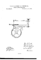
In the drawing, A is the cast-metal frame of the machine. A jaw is formed by the projecting lip B, through which passes a setscrew for the purpose of clamping it firmly to a table or other support. The fly-wheel C is hung upon a suitable pivot or stud at the lower extremity of the frame A. A horizon t-al table, D, upon which the work to be sawed rests, is fastened by screws at E. The vertical part of the frame, which for convenience we designate as the standard F, is fitted with a transverse V-shaped groove on top and a knife-edge on the lower side.
The arms G and H are of tough and elastic wood. Plates I and K, the upper one having a knife-edge and the lower one a V-shaped groove to fit the groove and knife-edge of the standard F, are attached to the forward ends of the arms G and H, and the arms are held in place upon the standard by the strainingrod L. Upon the smaller ends of the arms G and H are attached the plates M and N, each carrying pivoted upon it the clamps O and P, which receive and hold the ends of the saw-blade. The upper end of the pitman is connected by a pin to the plate N, and the lower end to the crank-wrist of the fiy-wheel, and the motion thus transmitted to the saw. The thumbnut R, on the straining-rod L, is used to bring a sufficient strain upon the blade to keep it taut, and also to adjust the arms for blades of varying lengths. This nut is capped, and contains within it a spiral spring which presses on the top of the upper arm,
when from any cause the saw is disconnected, and brings it down upon the projecting lip or rest X of the standard, and at once arrests its motion without danger of injury to either the hands of the operator or to delicate work from broken pieces of the saw-blade which may remain in the clamp.
The clamps O and P are pivoted to the plates which attach them to the arms, the object being that when the saw-blade is forced out of a perpendicular line by the too rapid feeding of the wood by the operator, the clamp itself, swinging upon, its pivot, will yield a little, and save the blade from being pressed against the rigid neck of the clamp, whereby the saw-blades are frequently broken.
In other arrangements of this kind of machinery, so far as we know, it is the custom to put both knife-edges on the same part; but as we arrange them we get both V-shaped grooves, with their mouths or open parts, turned upward, so that they will hold oil for lubricating the bearings. We also make the plates with a little transverse rib, which, fitting into corresponding depressions in the standards, prevent any lateral movement of the vibrating saw-arms.
The treader mechanism for operating this, machine will be made the subject of a separate application; but the machine, as here described, can be worked to advantage by any suitable foot-power, or by a belt from a pulley driven by steam.
Having thus described our invention, what we claim as new, and desire to secure by Letters Patent, is-
1. The cast-metal frame A, having the jaw and set-screw, by which it is fastened to a table with the dropping arm, upon which is hung the fly-wheel C, and with the vertical standard F with its projecting lip or rest X.
2. In a scroll-sawing machine, made with vibrating arms, the combination of a stop or rest, X, for the back end of the saw-arm, with the auxiliary spring and capped nut 011 the straining-rod, to hold the upper arm at rest,
and both arms in their bearings when the saw-blade is from any cause disconnected.
3. In a scroll-sawing machine, substanour own we affix our signatures in presence of tially as described, the combination of the two witnesses.
frame A, having the stop or rest X, fiy-wheel CHAS. N. TRUMP.
0, table D,vibratin g arms G and H, connected SAML. N. TRUMP.
by a rod, L, provided with a spring-nut at its CHRISTIAN FREDERICK. upper end, pivoted clamps O and P, and pit- Witnesses:
man connecting the lower arm and fly-wheel. E. B. FRAZER,
In testimony that we claim the foregoing as EDWARD MGINALL.
Publications (1)
| Publication Number | Publication Date |
|---|---|
| US185270A true US185270A (en) | 1876-12-12 |
Family
ID=2254675
Family Applications (1)
| Application Number | Title | Priority Date | Filing Date |
|---|---|---|---|
| US185270D Expired - Lifetime US185270A (en) | Improvement in scroll-sawing machines |
Country Status (1)
| Country | Link |
|---|---|
| US (1) | US185270A (en) |
-
0
- US US185270D patent/US185270A/en not_active Expired - Lifetime
Similar Documents
| Publication | Publication Date | Title |
|---|---|---|
| US189461A (en) | Improvement in scroll-saws | |
| US185270A (en) | Improvement in scroll-sawing machines | |
| US220705A (en) | Improvement in scroll-saws | |
| US257309A (en) | Scroll-sawing machine | |
| US752738A (en) | Hand-lever attachment for sewing-machines | |
| US775247A (en) | Sawing-machine. | |
| US332391A (en) | Albert d | |
| US157703A (en) | Improvement in machines for making wooden gutters | |
| US136433A (en) | Improvement in scroll-sawing machines | |
| USRE7938E (en) | Improvement in toy scroll-sawing machines | |
| US29009A (en) | Device for straining scroll-saws | |
| US13357A (en) | Circular-saw mandrel | |
| US212326A (en) | Improvement in scroll-sawing machines | |
| US123211A (en) | William weavee | |
| US816621A (en) | Churning-machine. | |
| US207640A (en) | Improvement in scroll-sawing machines | |
| US259928A (en) | Drag-saw | |
| US196796A (en) | Improvement in scroll-sawing machines | |
| US12287A (en) | Improvement in feeding mortising-machines | |
| US518656A (en) | Saw-handle | |
| US93138A (en) | Improvement in gig sawing-machine | |
| US261322A (en) | Drag-saw | |
| US130618A (en) | Improvement in band sawing-niachines | |
| US139284A (en) | Improvement in scroll-saws | |
| US1260793A (en) | Treadle mechanism. |