US1852705A - Mold and unloading device for same - Google Patents
Mold and unloading device for same Download PDFInfo
- Publication number
- US1852705A US1852705A US386765A US38676529A US1852705A US 1852705 A US1852705 A US 1852705A US 386765 A US386765 A US 386765A US 38676529 A US38676529 A US 38676529A US 1852705 A US1852705 A US 1852705A
- Authority
- US
- United States
- Prior art keywords
- mold
- sides
- molds
- pins
- unloading
- Prior art date
- Legal status (The legal status is an assumption and is not a legal conclusion. Google has not performed a legal analysis and makes no representation as to the accuracy of the status listed.)
- Expired - Lifetime
Links
- 239000000463 material Substances 0.000 description 6
- 238000005192 partition Methods 0.000 description 4
- 239000000203 mixture Substances 0.000 description 3
- 230000003028 elevating effect Effects 0.000 description 2
- 238000004519 manufacturing process Methods 0.000 description 2
- 239000002699 waste material Substances 0.000 description 2
- 239000000470 constituent Substances 0.000 description 1
- 238000004049 embossing Methods 0.000 description 1
- 239000002184 metal Substances 0.000 description 1
- 230000000284 resting effect Effects 0.000 description 1
Images


Classifications
-
- B—PERFORMING OPERATIONS; TRANSPORTING
- B29—WORKING OF PLASTICS; WORKING OF SUBSTANCES IN A PLASTIC STATE IN GENERAL
- B29C—SHAPING OR JOINING OF PLASTICS; SHAPING OF MATERIAL IN A PLASTIC STATE, NOT OTHERWISE PROVIDED FOR; AFTER-TREATMENT OF THE SHAPED PRODUCTS, e.g. REPAIRING
- B29C33/00—Moulds or cores; Details thereof or accessories therefor
- B29C33/20—Opening, closing or clamping
- B29C33/26—Opening, closing or clamping by pivotal movement
-
- B—PERFORMING OPERATIONS; TRANSPORTING
- B29—WORKING OF PLASTICS; WORKING OF SUBSTANCES IN A PLASTIC STATE IN GENERAL
- B29C—SHAPING OR JOINING OF PLASTICS; SHAPING OF MATERIAL IN A PLASTIC STATE, NOT OTHERWISE PROVIDED FOR; AFTER-TREATMENT OF THE SHAPED PRODUCTS, e.g. REPAIRING
- B29C33/00—Moulds or cores; Details thereof or accessories therefor
- B29C33/34—Moulds or cores; Details thereof or accessories therefor movable, e.g. to or from the moulding station
-
- B—PERFORMING OPERATIONS; TRANSPORTING
- B29—WORKING OF PLASTICS; WORKING OF SUBSTANCES IN A PLASTIC STATE IN GENERAL
- B29C—SHAPING OR JOINING OF PLASTICS; SHAPING OF MATERIAL IN A PLASTIC STATE, NOT OTHERWISE PROVIDED FOR; AFTER-TREATMENT OF THE SHAPED PRODUCTS, e.g. REPAIRING
- B29C37/00—Component parts, details, accessories or auxiliary operations, not covered by group B29C33/00 or B29C35/00
- B29C37/0003—Discharging moulded articles from the mould
-
- B—PERFORMING OPERATIONS; TRANSPORTING
- B29—WORKING OF PLASTICS; WORKING OF SUBSTANCES IN A PLASTIC STATE IN GENERAL
- B29C—SHAPING OR JOINING OF PLASTICS; SHAPING OF MATERIAL IN A PLASTIC STATE, NOT OTHERWISE PROVIDED FOR; AFTER-TREATMENT OF THE SHAPED PRODUCTS, e.g. REPAIRING
- B29C39/00—Shaping by casting, i.e. introducing the moulding material into a mould or between confining surfaces without significant moulding pressure; Apparatus therefor
Definitions
- the present invention relates to molds for compositions of matter and to unloading devices for the same.
- compositions of matter In the manufacture vof many compositions of matter, it is common to prepare them by conducting the compoundingV of the constituents at a temperature at which some or all are fusible and to pour such compositions in suitable molds to cool and form cakes. With the usual type of mold the removal of the cakes therefrom is somewhat diicult and laborious;
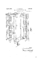
- Figure 1 is a side elevation of the unloading machine with a mold thereon.
- Figure 2 is an end elevation of the same.
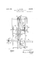
- Figure 3 is an enlarged partly sectional view of the mechanism for elevating and opening the mold.
- Figure 4 is a similar view of part of the mechanism of Figure 3 showing a mold in end view and closed.
- Figure 5 is a sectionon line 5'-5 of Figure 4.
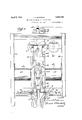
- Figures 6 and 7 are respectively side and end elevations of the mechanism for preventing the swinging of the mold.
- Figures 8 and 9 are respectively a plan view' of a mold and a section on line 9--9 of Figure 8.
- the machine is shown as comprising a frame work 20 carrying near its lower vend tracks 21 for the roller hangers 22 of the molds, one of which is indicated 'at 23.
- These molds consist of the end pieces 24, preferably channel members, to which are riveted the'hangers 23 and which are integral with a bottom member 25.
- a single piece of Achannel will be bent near its ends into U-shape and this ⁇ forms the frame of the mold.
- the sides 26 ofthe mold are hinged to the bottom portiom as indicated 41 mounted on a shaft 42 carrying a sprocket best in Figures 1 and 9 and the mold ⁇ will be divided by sheet metal vpartition members 27 which are so arranged that each alternate partition member 27 is set at an angle to the intervening partition members 27a so that the mold is divided into a number of trapezoidal shaped chambers open at both sides when the sides 26 are let down.
- the molds 23 are lilled with the material at somesuitable point, rolled down upon theV tracks 21 and stopped at any suitable point before entering the frame 20.
- a movable stop member 30 When it is desired to unload one of the molds,'it is allowed to travel further down the track 21 until it reaches a movable stop member 30.
- This stop member is hinged to the frame as at 31 and may be moved out of the path of the'mold by. means of a lever 32 hinged at 33 and connected to the stop member.
- the connection comprises a crank arm le 34 fixed to the shaft 33 to which leve-r 32 is keyed and which arm is connected to the stop member-30 through a link 35 so that when the ⁇ lever 32 is moved clockwise, it pulls the stop member 3G out of the way ofthe mold and 75 allows the latter to continue on down the track.
- a vertically arranged rack 40 to which, at its lower end, is connected a short section 21a of the track 21 which is disconnected from the balanceof the track and is movable with the rack 40.
- This rack is moved vertically through the operation of a crank S5 wheel 43.
- the sprocket wheel ⁇ 43 drives a chain 44 which in turn drives a shaft 45 carrying the gears 46 over at each end of the machine adapted to actuate the two racks 40.
- Each mold at its ends is provided with a double ended catch member 48 mounted ro:- tatably as at V49 on the endpieces 24.
- This catch member 48 holds the sides of the mold closed, but is provided with a projection 50 which strikes the lower end 51 of one of the guide ways 47 and thus releases the two sides of the mold.
- the ends Upon further elevation of the mold by means of the rack, the ends travel in the guide ways 47 and the latter being diverging, cause the sides of the mold to flatten out until the mold reaches the condition indicated in Figure 3.
- the rack is then further elevated lifting the mold until it reaches the position A, indicated in Figure 3, and in position to be unloaded.
- the sides 26 have been dropped down and are prevented from reaching a vertical position vby the curved guide members 55, which being pivoted at 56, allow the pins 46 to pass under them as the sides 26 are moved to the position B of Figure 3, but immediately drop behind the pins, as indicated in this figure, the dotted line position of guides 55 indicating ⁇ the position when the pins are passing thereunder.
- crank handle (Fig. 1) is rocked and this causes the rocking of two shafts 61 geared to each other and to the shaft on which the crank handle 60 is mounted, so as to move the lingers 62 on shafts 61 toward each other.
- These lingers 62 are so arranged that they strike the cakes of material in the mold en the narrow side and force them outwardly, wherein they drop upon belt conveyors 63 mounted on rollers 64 carried by the frame. The material is then carried by the conveyors to one end of the machine and dropped upon a platform 65 from which it may be removed and disposed of. y
- crank 41 is rotated in a reverse direction to lower the rack 40 and the mold is lowered therewith.
- thc mold described above provides for the individual molds to be arranged in the gang mold on end and with a very narrow dividing ⁇ element between them. This arrangement provides for only a very small amount of waste of the material in passing from one mold to the neXt.
- the divisions between the molds are usually of greater width than the partitions 27 and 27a and on account of the length of the mold there is apt to be oonsiderable material lying on the top of the dividing element when the mold has been lilled.
- These connecting pieces of the molded may-- terial form fins which are easily broken off and are so much waste material.
- An unloading machine for molds having their sides hinged comprising means for means to release said sides, means to remove the mold contents, and means to return the sides to closed position.
- a mold having hinged sides, with longitudinally extending pins on said sides, and an unloader therefor comprising means to release said sides, guides for said pins arranged to move positively said sides to open position, means to remove the mold contents, and means to return Vthe sides to closed position.
- a mold having hinged sides, and an unloader therefor comprising means for transferring said molds from a transporting position to an unloading position, means to release said sides, means to remove the mold contents, and means to return the sides to closed position.
- a mold having hinged sides, with longitudinally extending pins on said sides, and an unloader therefor comprising means for transferring said molds from a transporting position to an unloading position, means to release said sides, guides for said pins arranged-to move positively said sides to open position, means to remove the mold contents, and means to return the sides to closed position.
- a mold having hinged sides, with longitudinally extending pins on said sides, and an unloader therefor comprising means to elevate said molds to an unloading position, outwardly diverging guideways for said pins for moving said sides to open position during such elevation, means for removing the mold contents while in elevated position, means for lowering said molds, said guides acting to close said sides during said lowering, and means for conveying to a point of discharge the unloaded mold contents.
- a mold having hinged sides, with longitudinally extending pins on said sides, and an unloader therefor comprising means to elevate said molds to an unloading position, means to prevent lateral movement of said molds, outwardly diverging guideways for said pins for moving said sides to open position during such elevation, means for removing the mold contents while in elevated position, means for lowering said molds, said guides acting to close said sides during said lowering, and means for conveying to a point of discharge the unloaded mold contents.
- a gang mold comprising a horizontally disposed smooth surfaced bottom member upon which articles of manufacture may be disposed, transverse partition members extending from side to side and projecting upwardly from said bottom member, these forming the only stationary parts projecting upwardly from said bottom member, and a pair of l, side walls or wings pivotally connected to the bottom member on opposite side edges of the latter, the pivotal mounting being such as to enable the side walls to be moved upwardly to vertical position, whereby they may form a closed gang mold, or to be moved downwardly, to or below horizontal position to leave the bottom member free to be engaged by members movable towards the mold from the sides thereof and free of obstructions which would prevent the molded articles from being swept off the mold, laterally, each of said side walls having means on its end edges whereby the side walls may be guided in their movement by cooperating parts of the machine, said means comprising pins adapted to ride in slots in the machine frame.
Landscapes
- Engineering & Computer Science (AREA)
- Mechanical Engineering (AREA)
- Moulds For Moulding Plastics Or The Like (AREA)
Description
April 5, 1932- R. EASTMAN 1,852,705
MOLD AND UNLOADING `DEVCE FOR SAME Filed Aug. 19, 1929 5 Sheets-Sheet 2 (y. n? lNl'oR. I aa/ala ATTORNEY.
April 5, 1932. L.. R. f-:AsTMAN MOLD AND UNLOADING DEVICE FOR SAME Filed Aug. 19, 1929 5 Sheets-Sheet 3 5 .sheets-Sheet 4 lll.
I INVENTOR.
BY MM ATTORNEY.
'L.. R. EASTMAN Filed Aug. 19, 1929 MLD AND UNLOADING DEVICE FOR SAME April 5, 1932.
April 5, 1932- L. R. EASTMAN 1,852,705
MOLD AND UNLOADING DEVICE FOR SAME Filed Aug. 19, 1929 5 sheets-sheet 5 I N VEN TOR.
inw 7/ g A TTORNEY.
Patented Apr. 5, 1932v UNITED STATES PATENT OFFICE LOUIS R. EASTM'AN, OF DETROIT, MICHIGAN, ASSIGNOR TO FREDERIC B. STEVENS, INC.,
OF DETROIT,VMIGHIGAN, A CORPORATION F IMICHIGAN MOLD AND UNLOADING DEVICE FOR SAME Application led August 19, 1929. Serial No. 386,765.
The present invention relates to molds for compositions of matter and to unloading devices for the same.
In the manufacture vof many compositions of matter, it is common to prepare them by conducting the compoundingV of the constituents at a temperature at which some or all are fusible and to pour such compositions in suitable molds to cool and form cakes. With the usual type of mold the removal of the cakes therefrom is somewhat diicult and laborious;
Among the objects ofthe present invention is to overcome such objections andv greatly decrease the labor thereof and to provide a mold and unloading mechanism that will quickly and efliciently remove such cakes with a minimum of labor.
Other objects will readily occur to those skilled in the art upon reference to the following description and the accompanying drawings in which Figure 1 is a side elevation of the unloading machine with a mold thereon.
Figure 2 is an end elevation of the same.
Figure 3 is an enlarged partly sectional view of the mechanism for elevating and opening the mold.
Figure 4 is a similar view of part of the mechanism of Figure 3 showing a mold in end view and closed.
Figure 5 is a sectionon line 5'-5 of Figure 4.
Figures 6 and 7 are respectively side and end elevations of the mechanism for preventing the swinging of the mold.
Figures 8 and 9 are respectively a plan view' of a mold and a section on line 9--9 of Figure 8. I
In the drawings, the machine is shown as comprising a frame work 20 carrying near its lower vend tracks 21 for the roller hangers 22 of the molds, one of which is indicated 'at 23. These molds consist of the end pieces 24, preferably channel members, to which are riveted the'hangers 23 and which are integral with a bottom member 25. In forming the mold, a single piece of Achannel will be bent near its ends into U-shape and this `forms the frame of the mold. The sides 26 ofthe mold are hinged to the bottom portiom as indicated 41 mounted on a shaft 42 carrying a sprocket best in Figures 1 and 9 and the mold `will be divided by sheet metal vpartition members 27 which are so arranged that each alternate partition member 27 is set at an angle to the intervening partition members 27a so that the mold is divided into a number of trapezoidal shaped chambers open at both sides when the sides 26 are let down.
The molds 23 are lilled with the material at somesuitable point, rolled down upon theV tracks 21 and stopped at any suitable point before entering the frame 20. v
When it is desired to unload one of the molds,'it is allowed to travel further down the track 21 until it reaches a movable stop member 30. This stop member is hinged to the frame as at 31 and may be moved out of the path of the'mold by. means of a lever 32 hinged at 33 and connected to the stop member. The connection comprises a crank arm le 34 fixed to the shaft 33 to which leve-r 32 is keyed and which arm is connected to the stop member-30 through a link 35 so that when the `lever 32 is moved clockwise, it pulls the stop member 3G out of the way ofthe mold and 75 allows the latter to continue on down the track. i I
Mounted at each end in the' frame 2O above the track 21 is a vertically arranged rack 40 to which, at its lower end, is connected a short section 21a of the track 21 which is disconnected from the balanceof the track and is movable with the rack 40. This rack is moved vertically through the operation of a crank S5 wheel 43. The sprocket wheel`43 drives a chain 44 which in turn drives a shaft 45 carrying the gears 46 over at each end of the machine adapted to actuate the two racks 40. When the racks are lifted vertically, they carry with them the track section 21a upon which is resting one of the molds 23.` This elevates the mold and after it has moved a short distance the pins 46, with which each side is provided at its ends, enter guide ways 47 mounted on the framework a short distance above the track level.
Each mold at its ends is provided with a double ended catch member 48 mounted ro:- tatably as at V49 on the endpieces 24. This catch member 48 holds the sides of the mold closed, but is provided with a projection 50 which strikes the lower end 51 of one of the guide ways 47 and thus releases the two sides of the mold. Upon further elevation of the mold by means of the rack, the ends travel in the guide ways 47 and the latter being diverging, cause the sides of the mold to flatten out until the mold reaches the condition indicated in Figure 3.
The rack is then further elevated lifting the mold until it reaches the position A, indicated in Figure 3, and in position to be unloaded. In the meantime, the sides 26 have been dropped down and are prevented from reaching a vertical position vby the curved guide members 55, which being pivoted at 56, allow the pins 46 to pass under them as the sides 26 are moved to the position B of Figure 3, but immediately drop behind the pins, as indicated in this figure, the dotted line position of guides 55 indicating` the position when the pins are passing thereunder.
'When the mold has reached the position A of Figure 3, the crank handle (Fig. 1) is rocked and this causes the rocking of two shafts 61 geared to each other and to the shaft on which the crank handle 60 is mounted, so as to move the lingers 62 on shafts 61 toward each other.
These lingers 62 are so arranged that they strike the cakes of material in the mold en the narrow side and force them outwardly, wherein they drop upon belt conveyors 63 mounted on rollers 64 carried by the frame. The material is then carried by the conveyors to one end of the machine and dropped upon a platform 65 from which it may be removed and disposed of. y
After the material has been removed from the mold, the crank 41 is rotated in a reverse direction to lower the rack 40 and the mold is lowered therewith.
On the downward motion, the sides 26 move from'position A to position Band at the same time, of course, the mold body moves to the full line position of Figure 3. The further downward movement of the mold, of course, causes the pins 46 of the mold -to move inwardly again and when the latter are about to strike the ends of the guides'55, these are lifted by the striking of the projections 5511 by the catch member 48 so as to allow the pins to pass under the guides 55 and into guides 47.
As the pins pass out of the lower ends of Vthe guides 47, the sides 26 are by this time completely closed and the catch member 48 holds them in this condition. Then the track section 21a has finally reached its alignment with the rest of the track 21, the operation has been completed. Thereupon the stop member 30 is moved and the mold is allowed 'to travel further down the track.
In order to prevent the mold swinging when the elevating begins, it is preferred to continue the racks 40 below the track section 21a in the two members 40a, which at the top are spread apart by the lower end of the rack and to mount between them a lever which is provided with a lateral extension 71 having a foot F2 which is adapted to pass between the extended edges of the sides 26 of the mold and prevent any lateral sway thereof. rI his lever 70 is pivoted at its lower end as at 7 3 between the two members 40a and is provided with an extension 74 which has a link 75 connected to a similar lever at the other end of the lever 70, preferably above the pivot point of the latter.
When, therefore, the lever 7 O is moved to the dotted line postion of Figure 6, the lever on the opposite end is also moved out and a mold 23 may be put in position to be operated on. The lever 70 is then moved back into its vertical position and passes up with the mold and rack.
It will be noted that thc mold described above provides for the individual molds to be arranged in the gang mold on end and with a very narrow dividing` element between them. This arrangement provides for only a very small amount of waste of the material in passing from one mold to the neXt. In the ordinary flat gang mold the divisions between the molds are usually of greater width than the partitions 27 and 27a and on account of the length of the mold there is apt to be oonsiderable material lying on the top of the dividing element when the mold has been lilled. These connecting pieces of the molded may-- terial form fins which are easily broken off and are so much waste material.
Further, by arranging the molds facing alternately to one side and then the other, a saving in space may be accomplished over any arrangement of them allfacing the same side. And by hinging the sides of the gang mold so that the entire face of the mold is open, it is also possible to provide for embossing either the top or the bottom of the cake.
Now, having described the invention and the preferred forms of embodiment thereof, it is to be understood that the said invention is to be limited not to the specific details herel in set forth and illustrated, but only by the scope of the claims which follow:
I claim 1. An unloading machine for molds having their sides hinged, comprising means for means to release said sides, means to remove the mold contents, and means to return the sides to closed position.
3. In combination, a mold having hinged sides, with longitudinally extending pins on said sides, and an unloader therefor comprising means to release said sides, guides for said pins arranged to move positively said sides to open position, means to remove the mold contents, and means to return Vthe sides to closed position.
4i. In combination, a mold having hinged sides, and an unloader therefor comprising means for transferring said molds from a transporting position to an unloading position, means to release said sides, means to remove the mold contents, and means to return the sides to closed position.
5. In combination, a mold having hinged sides, with longitudinally extending pins on said sides, and an unloader therefor comprising means for transferring said molds from a transporting position to an unloading position, means to release said sides, guides for said pins arranged-to move positively said sides to open position, means to remove the mold contents, and means to return the sides to closed position.
6. In combination, a mold having hinged sides, with longitudinally extending pins on said sides, and an unloader therefor comprising means to elevate said molds to an unloading position, outwardly diverging guideways for said pins for moving said sides to open position during such elevation, means for removing the mold contents while in elevated position, means for lowering said molds, said guides acting to close said sides during said lowering, and means for conveying to a point of discharge the unloaded mold contents.
7 In combination, a mold having hinged sides, with longitudinally extending pins on said sides, and an unloader therefor comprising means to elevate said molds to an unloading position, means to prevent lateral movement of said molds, outwardly diverging guideways for said pins for moving said sides to open position during such elevation, means for removing the mold contents while in elevated position, means for lowering said molds, said guides acting to close said sides during said lowering, and means for conveying to a point of discharge the unloaded mold contents.
8. In a machine of the class described, a gang mold comprising a horizontally disposed smooth surfaced bottom member upon which articles of manufacture may be disposed, transverse partition members extending from side to side and projecting upwardly from said bottom member, these forming the only stationary parts projecting upwardly from said bottom member, and a pair of l, side walls or wings pivotally connected to the bottom member on opposite side edges of the latter, the pivotal mounting being such as to enable the side walls to be moved upwardly to vertical position, whereby they may form a closed gang mold, or to be moved downwardly, to or below horizontal position to leave the bottom member free to be engaged by members movable towards the mold from the sides thereof and free of obstructions which would prevent the molded articles from being swept off the mold, laterally, each of said side walls having means on its end edges whereby the side walls may be guided in their movement by cooperating parts of the machine, said means comprising pins adapted to ride in slots in the machine frame.
LOUIS R. EASTMAN.
Priority Applications (1)
| Application Number | Priority Date | Filing Date | Title |
|---|---|---|---|
| US386765A US1852705A (en) | 1929-08-19 | 1929-08-19 | Mold and unloading device for same |
Applications Claiming Priority (1)
| Application Number | Priority Date | Filing Date | Title |
|---|---|---|---|
| US386765A US1852705A (en) | 1929-08-19 | 1929-08-19 | Mold and unloading device for same |
Publications (1)
| Publication Number | Publication Date |
|---|---|
| US1852705A true US1852705A (en) | 1932-04-05 |
Family
ID=23526961
Family Applications (1)
| Application Number | Title | Priority Date | Filing Date |
|---|---|---|---|
| US386765A Expired - Lifetime US1852705A (en) | 1929-08-19 | 1929-08-19 | Mold and unloading device for same |
Country Status (1)
| Country | Link |
|---|---|
| US (1) | US1852705A (en) |
Cited By (1)
| Publication number | Priority date | Publication date | Assignee | Title |
|---|---|---|---|---|
| EP0686485A3 (en) * | 1994-06-10 | 1997-04-23 | Johnson & Johnson Vision Prod | Laser demolding apparatus and method |
-
1929
- 1929-08-19 US US386765A patent/US1852705A/en not_active Expired - Lifetime
Cited By (1)
| Publication number | Priority date | Publication date | Assignee | Title |
|---|---|---|---|---|
| EP0686485A3 (en) * | 1994-06-10 | 1997-04-23 | Johnson & Johnson Vision Prod | Laser demolding apparatus and method |
Similar Documents
| Publication | Publication Date | Title |
|---|---|---|
| US2948382A (en) | Box stacking mechanism | |
| US2897949A (en) | Box-stacking mechanism | |
| US1858619A (en) | Tray carrying conveyer | |
| US1852705A (en) | Mold and unloading device for same | |
| US1794331A (en) | Vertical conveyer | |
| US1795352A (en) | Feed mechanism for bake ovens | |
| US1476050A (en) | Apparatus for handling freshly-formed sections of plaster board | |
| US2936875A (en) | Endless belt trough conveyors | |
| US2193264A (en) | Stacking mechanism | |
| US1905379A (en) | Conveying system | |
| US2770350A (en) | Automatic self-filling conveyor | |
| US2631716A (en) | Endless flight conveyer | |
| US2549341A (en) | Pan spacer | |
| US1636429A (en) | Automatic transfer mechanism for conveyers | |
| US877141A (en) | Conveyer. | |
| US1860679A (en) | Conveyer | |
| US3018872A (en) | Tray for baking oven | |
| US1507301A (en) | williams | |
| US1056767A (en) | Pan elevator and conveyer. | |
| US1957321A (en) | Feeding appliance for bread slicing machines | |
| US2936061A (en) | Article-handling devices | |
| US1902088A (en) | Laundry sorting machine | |
| US2944653A (en) | Conveyor arrangement in plants for moulding chocolate and similar masses | |
| GB190088A (en) | Improvements in or relating to conveyors | |
| US2622718A (en) | Article transfer for proofer unloaders |